Nissan Rogue (T33) 2021-Present Service Manual: Transaxle Assembly
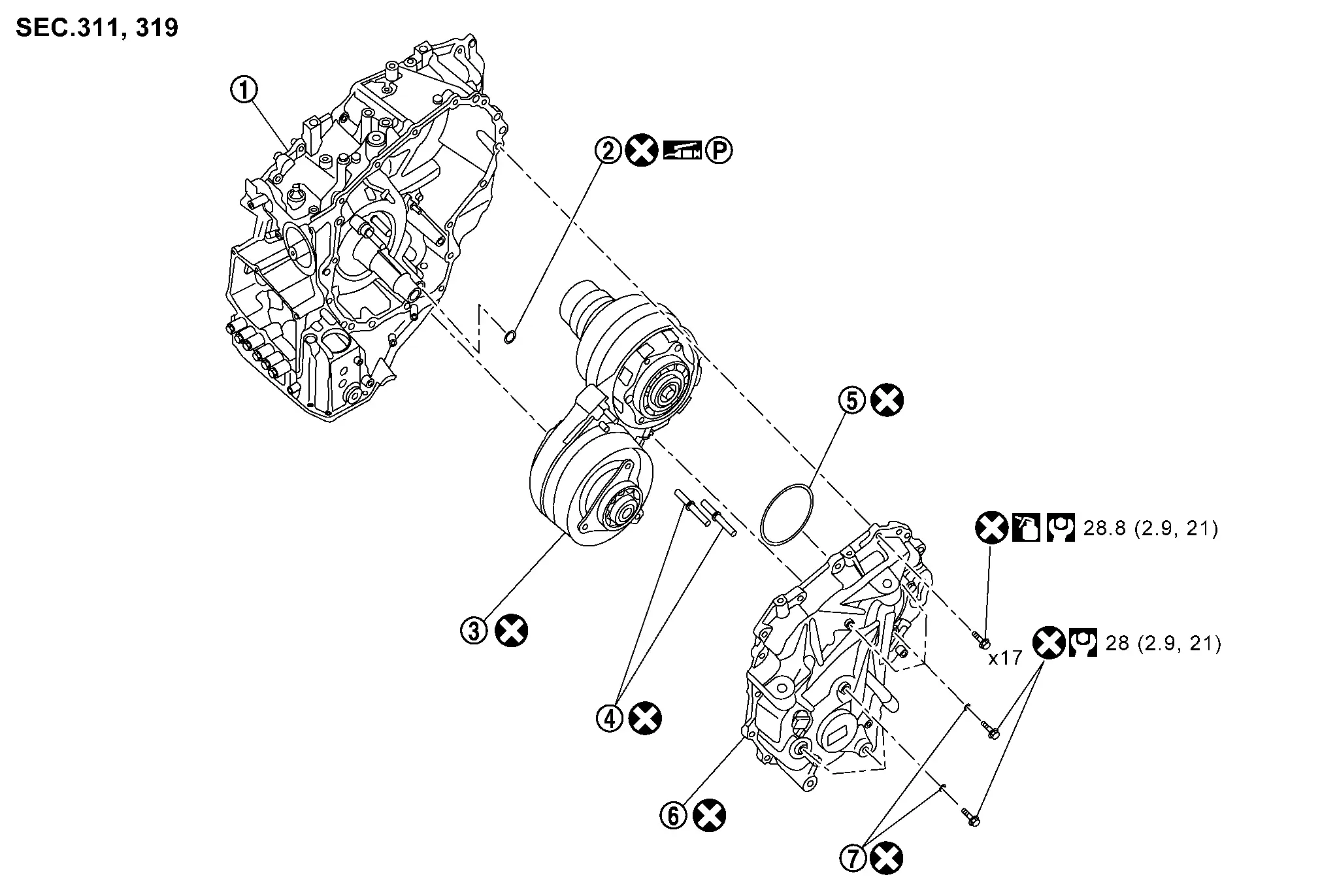
Exploded View
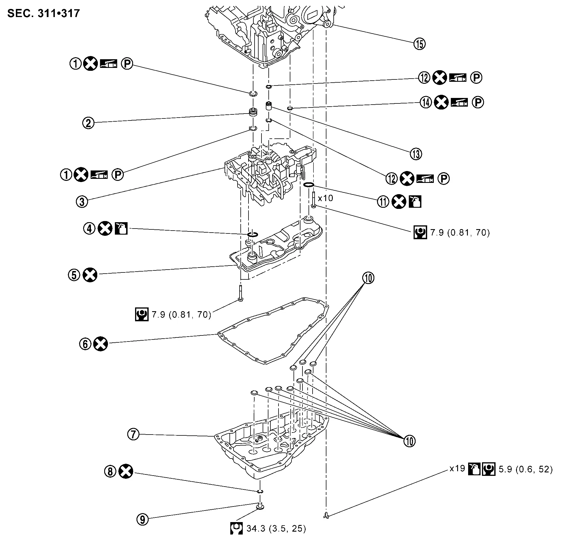
 |
O-ring |  |
Tube A |  |
Control valve |
 |
O-ring |  |
Oil strainer |  |
Oil pan gasket |
 |
Oil pan |  |
Drain plug gasket |  |
Drain plug |
 |
Magnet |  |
O-ring |  |
O-ring |
 |
Tube B |  |
Lip seal |  |
Transaxle assembly |
 |
: Always replace after every disassembly | ||||
 |
: N·m (kg-m, ft-lb) | ||||
 |
: N·m (kg-m, in-lb) | ||||
 |
: Apply CVT fluid | ||||
 |
: Apply petroleum jelly |
 |
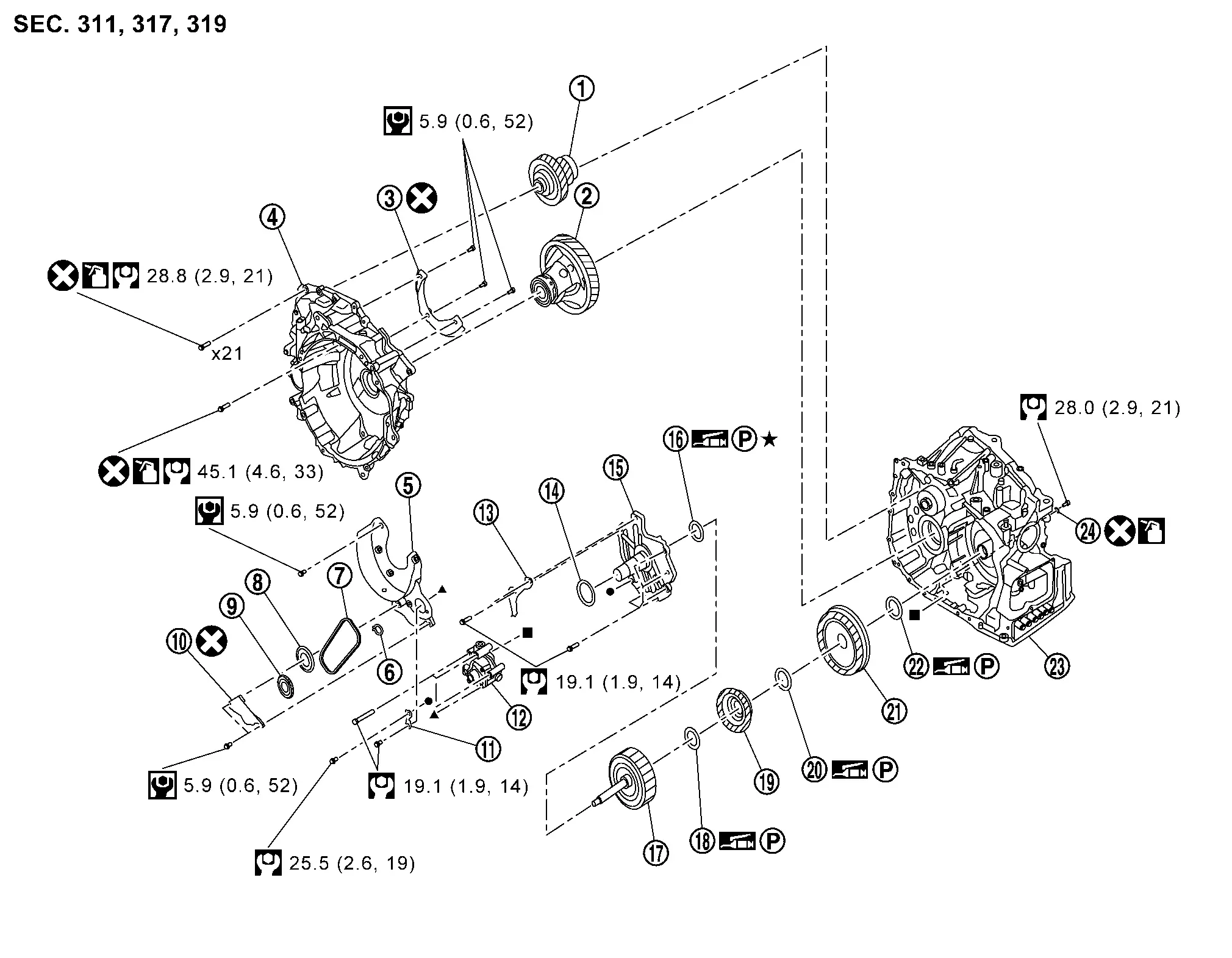
Reduction gear assembly |  |
Differential assembly |  |
Baffle plate C |
|
Converter housing | |
Baffle plate B | |
Snap ring |
|
Chain | |
Drive sprocket | |
Driven sprocket |
|
Baffle plate A | |
Oil pump bracket | |
Oil pump |
|
Baffle plate D | |
Thrust washer | |
Dummy cover |
 |
Thrust bearing |  |
Forward clutch |  |
Thrust bearing |
 |
Sun gear |  |
Thrust bearing |  |
Planetary carrier assembly |
 |
Thrust bearing |  |
Transaxle assembly |  |
O-ring |
|
: N·m (kg-m, in-lb) | ||||
|
: N·m (kg-m, ft-lb) | ||||
|
: Apply CVT fluid | ||||
|
: Apply petroleum jelly | ||||
|
: Always replace after every disassembly. | ||||
   |
: Indicates that the part is connected at points with same symbol | ||||
 |
: Select with proper thickness | ||||
|
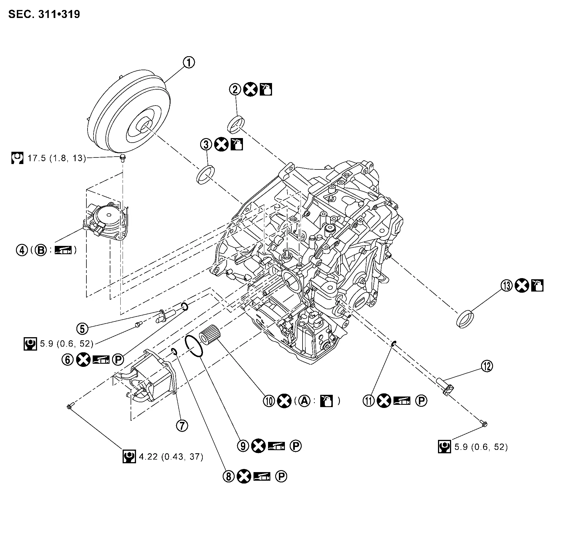
Torque converter | |
Differential side oil seal (2WD only) | |
Converter housing oil seal |
|
Shift actuator | |
Input speed sensor | |
O-ring |
|
CVT oil warmer | |
O-ring* | |
O-ring |
|
Oil filter | |
O-ring | |
Primary speed sensor |
|
Differential side oil seal | ||||
 |
Grommet |  |
Spline part | ||
|
: Always replace after every disassembly. | ||||
|
: N·m (kg-m, ft-lb) | ||||
|
: N·m (kg-m, in-lb) | ||||
|
: Apply CVT fluid | ||||
 |
: Lithium-based grease including molybdenum disulphide | ||||
|
: Apply petroleum jelly | *: There are one O-ring and two O-rings depending on the specifications. | |||
|
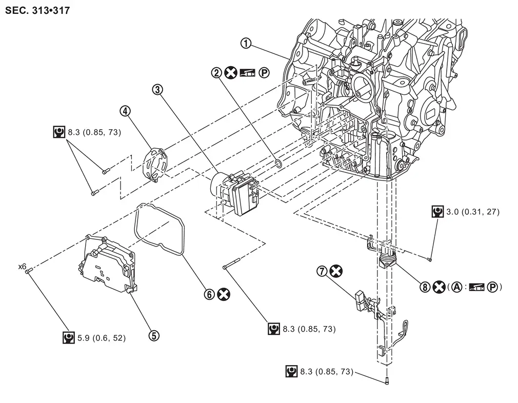
Transaxle assembly | |
Electric oil pump gasket | |
Electric oil pump |
|
Electric oil pump bracket | |
TCM | |
Gasket |
|
Terminal assembly B | |
Terminal assembly A | ||
|
O-ring | ||||
|
: Always replace after every disassembly. | ||||
|
: Apply petroleum jelly | ||||
|
: N·m (kg-m, in-lb) |
|
Transaxle case | |
O-ring | |
Belt and pulley assembly |
|
Lubrication cap | |
Secondary pulley shim | |
Side cover |
|
O-ring | ||||
|
: Always replace after every disassembly. | ||||
|
: N·m (kg-m, ft-lb) | ||||
|
: Apply petroleum jelly | ||||
|
: Apply CVT fluid | ||||
Disassembly & Assembly
DISASSEMBLY
CAUTION:
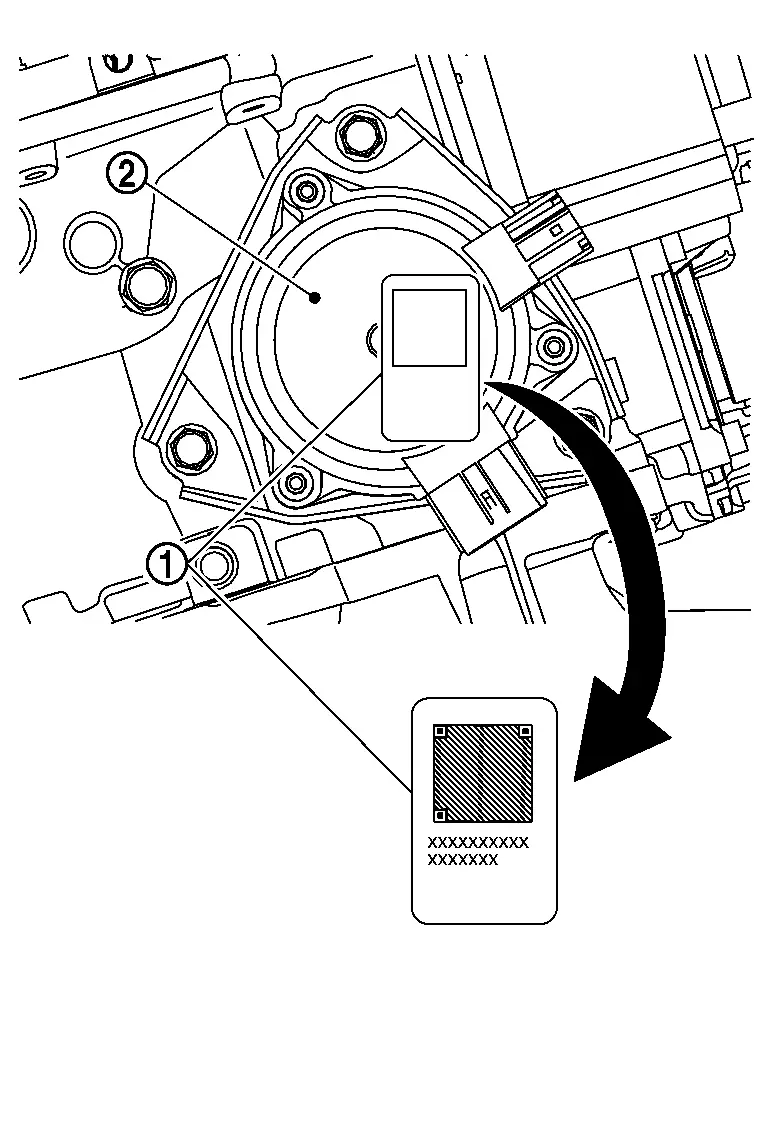
If old serial number sticker is affixed to shift actuator, remove the serial number sticker and affix new serial number sticker included with new control valve.
 NOTE:
NOTE:
New control valve assemblies may come with a CD-ROM, which is not used.
Remove the CVT from the vehicle. Refer to Removal and Installation.
Remove drain plug from oil pan and then drain the CVT fluid.
Remove drain plug gasket.
Mount the CVT on a workbench with the oil pan side down.
NOTE:
Use plastic or wood blocks to stabilize the transaxle assembly on the work bench if needed.
CAUTION:
Be sure not to deform the oil pan.
Remove torque converter from transaxle assembly.
NOTE:
Wipe out remaining CVT fluid in torque converter.
CAUTION:
-
While removing torque converter, never damage the bush in the sleeve of torque converter.
-
Completely drain CVT fluid from torque converter by tilting right and left several times until no fluid coming out.
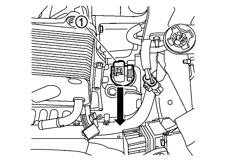
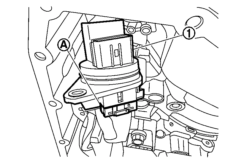
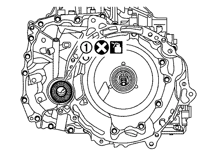
Remove primary pulley speed sensor mounting bolt and then remove primary pulley speed sensor .
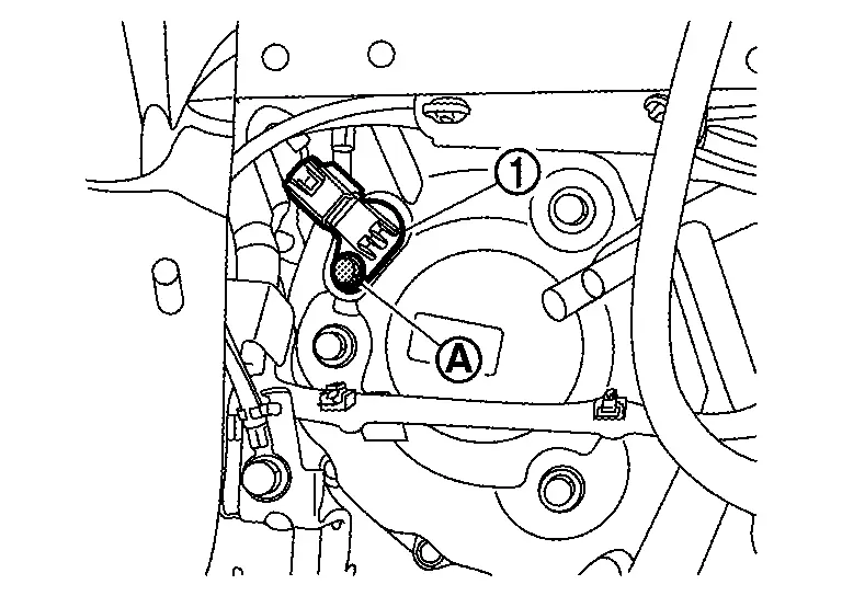
Remove O-Ring from primary speed sensor.
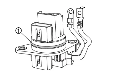
Remove input speed sensor mounting bolt and then remove input speed sensor .
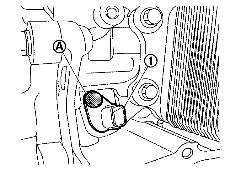
Remove O-ring from input speed sensor.
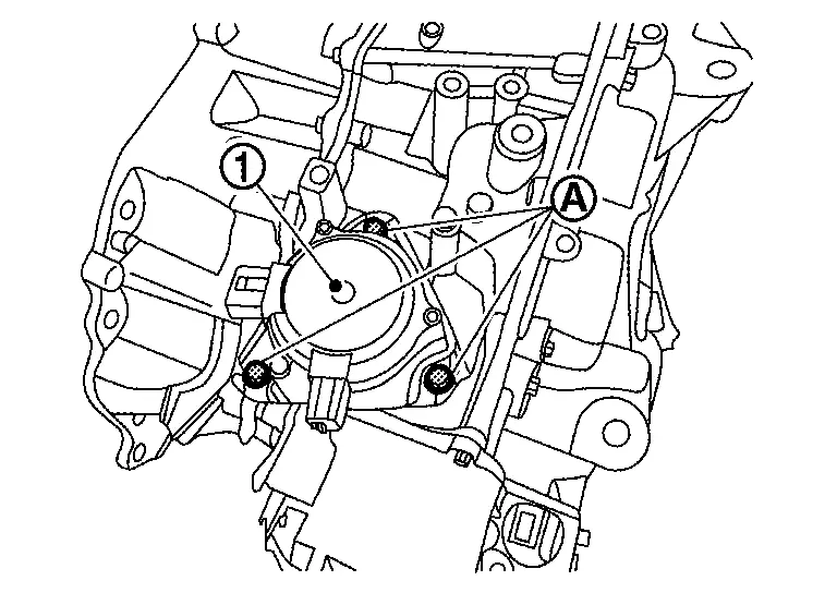
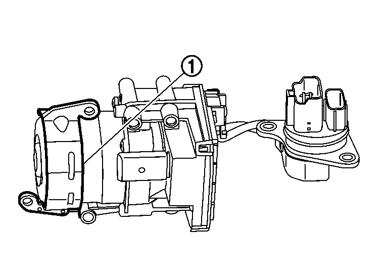
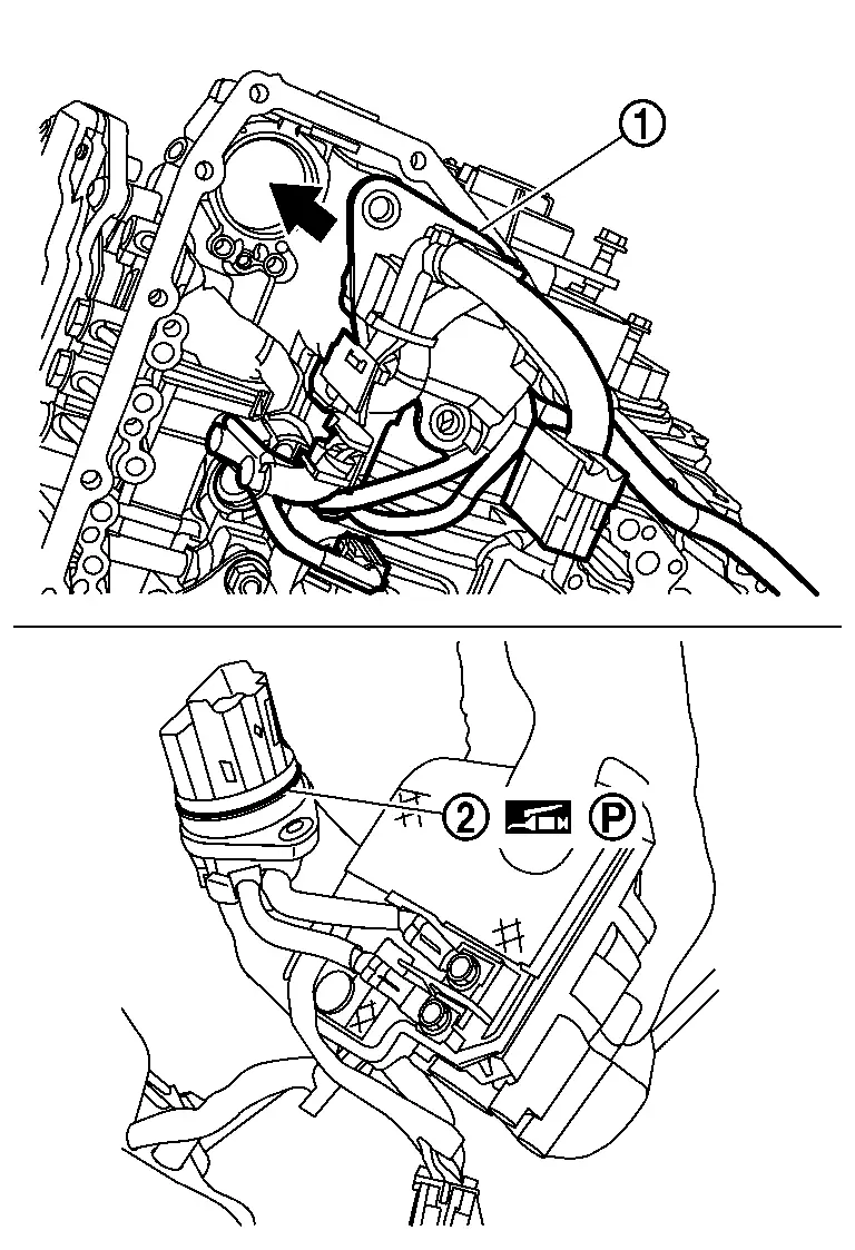
Remove shift actuator mounting bolt and then remove shift actuator .
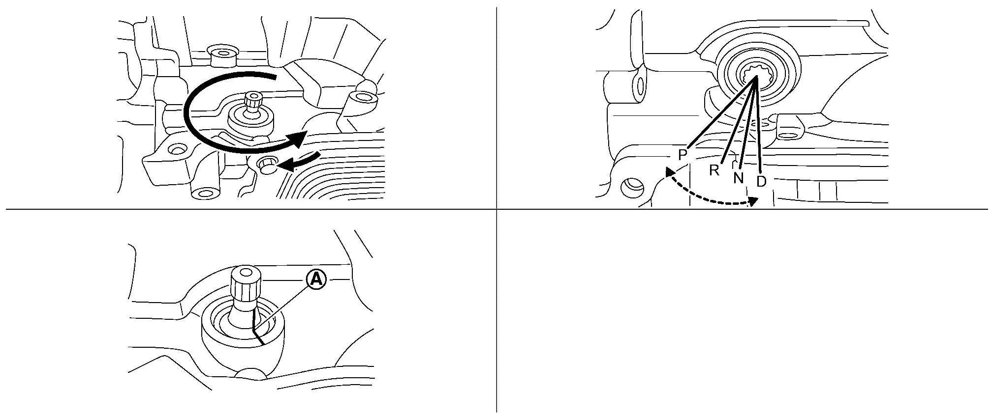
Marking is made to mark the
range position of the manual shaft.Turn the manual shaft by CVT range
switch adjuster (SST: NI-53061) counterclockwise until it hits, return
one position, and set to the N range. Put align mark on both of the
manual shaft and the case. Use this marking as a guide when align the
manual shaft with the N range.
Remove CVT oil warmer mounting bolts and then remove CVT oil warmer .
Remove O-ring and from CVT oil warmer.
NOTE:
There are one O-ring and two O-rings depending on the specifications. When reusing oil warmer, check the number of O-rings and use the same number of O-rings as the removed number.
-
Type with one O-ring
-
Type with two O-ring
Remove oil filter .
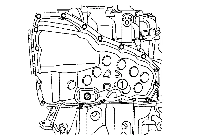
Remove oil pan mounting bolts ( 19 pieces) and then remove oil pan.
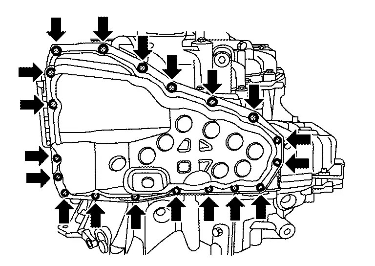
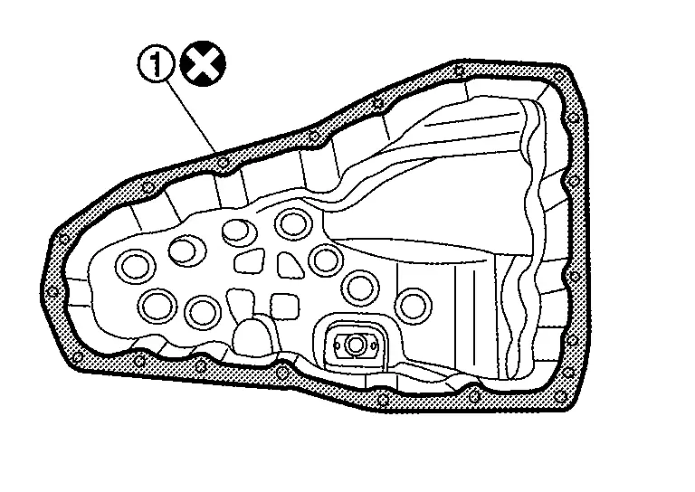
Remove oil pan gasket .
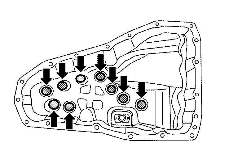
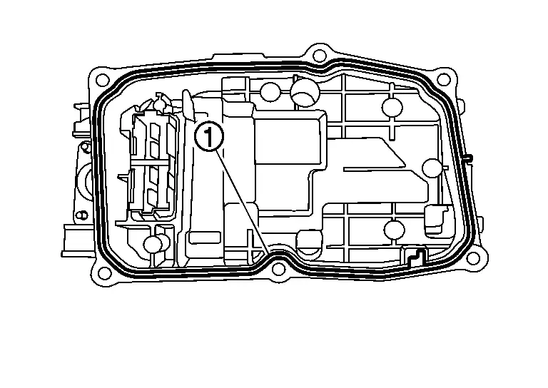
Remove oil pan magnets ( 9 pieces) from the oil pan.
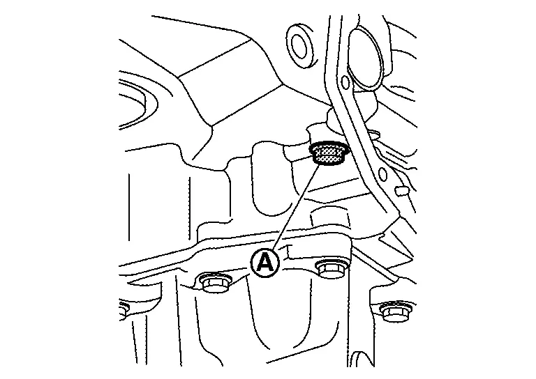
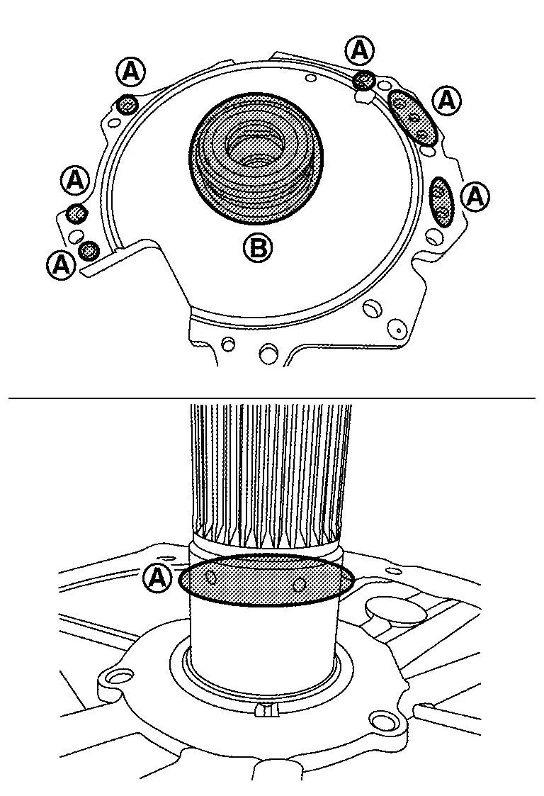
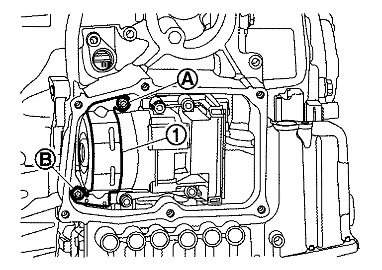
Remove oil strainer assembly mounting bolts and then remove oil strainer assembly .
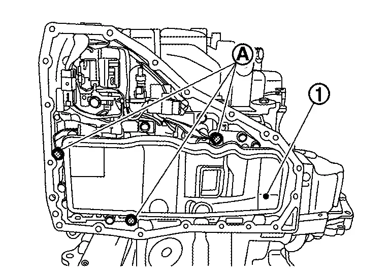
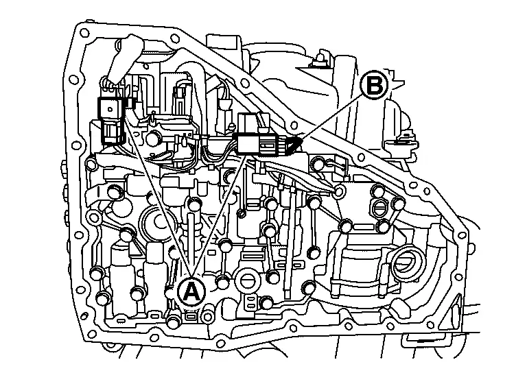
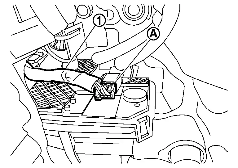
Remove harness connectors and harness clip .
CAUTION:
Never pull with excessive force when removing harness clip. Push tabs on the both side of harness clip properly to avoid damage.
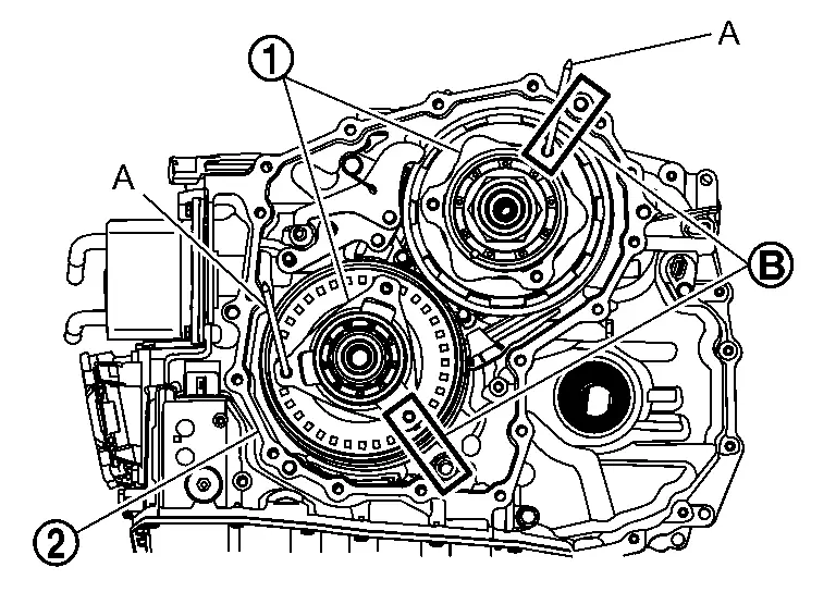
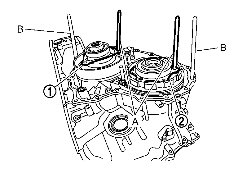
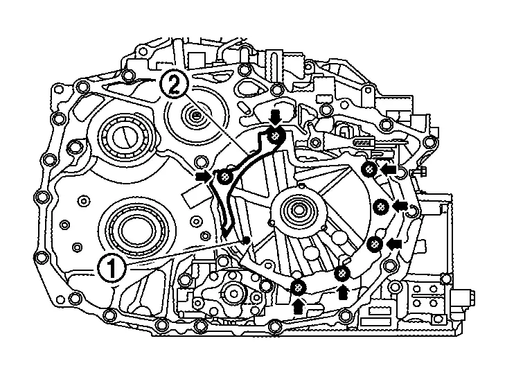
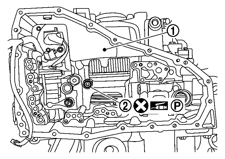
Remove bolts ( 10 pieces) which exists on the outline of control valve according to the sequence of , and  .
.
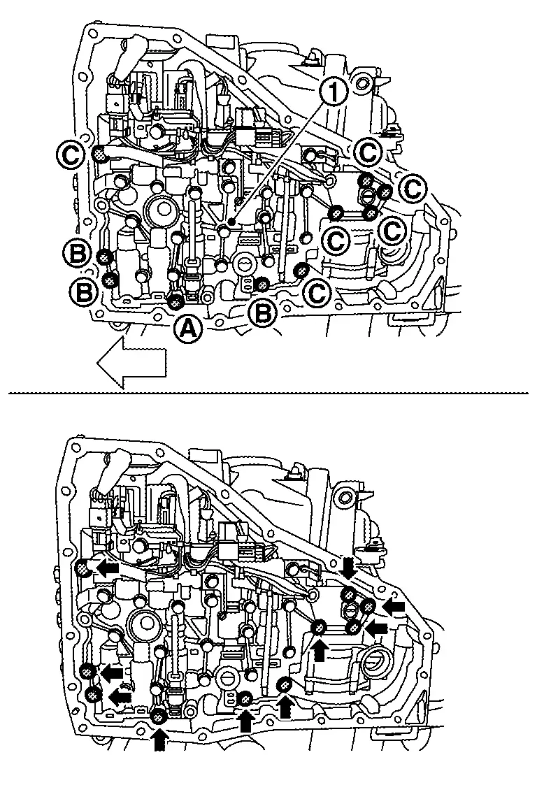
| : Nissan Ariya Vehicle front |
CAUTION:
Do not mix 3 types of bolts which were removed from control valve, and keep them separately.
| Bolt | Bolt length mm (in) | Number of bolt |
|---|---|---|
|
54 (2.13) | 1 |
|
44 (1.73) | 3 |
|
40 (1.57) | 6 |
Remove the control valve from transaxle case.
CAUTION:
Never drop the control valve.
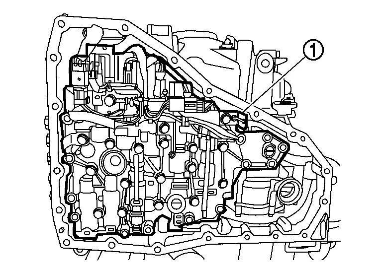
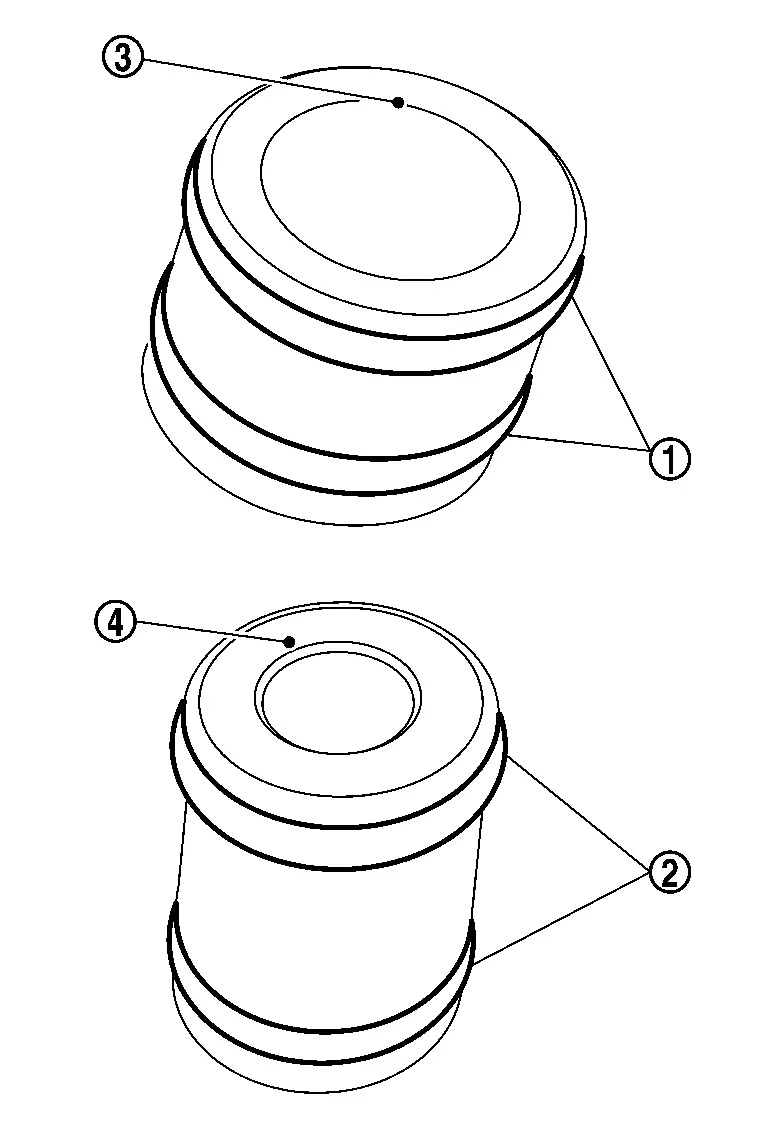
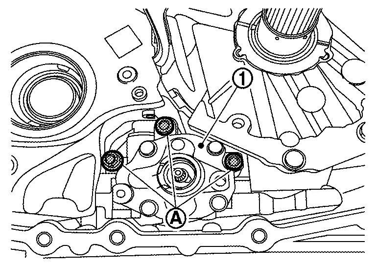
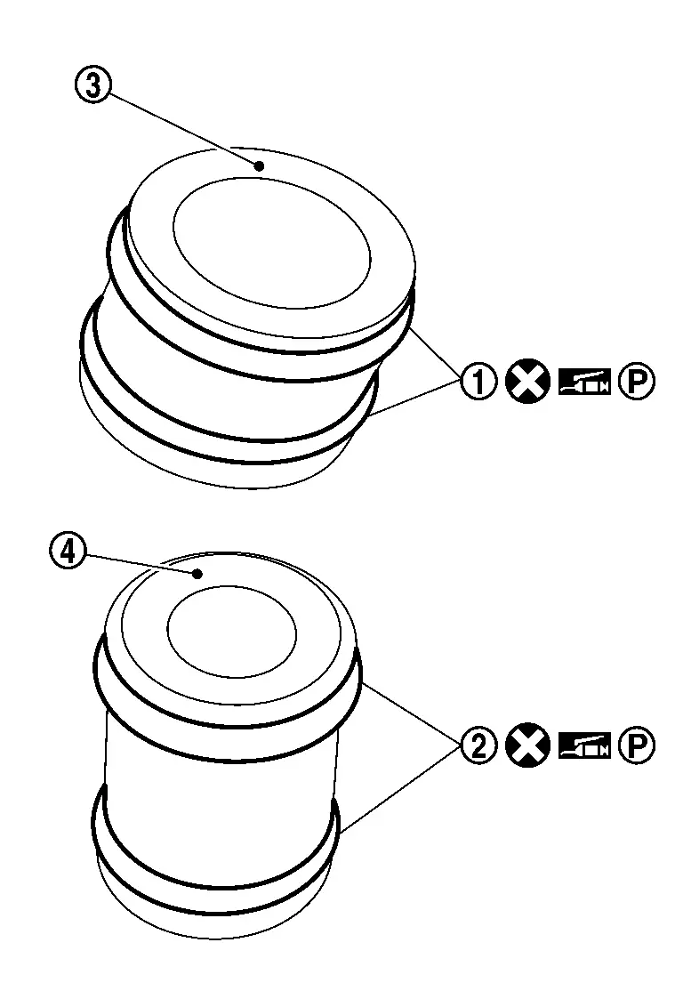
Remove tubes and from control valve .
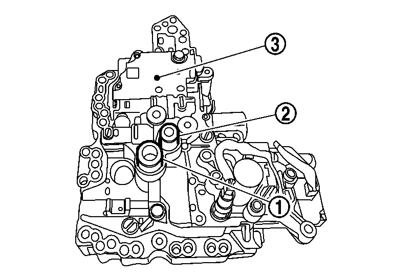
CAUTION:
-
While removing control valve, never drop tube if it is remaining with transaxle assembly.
-
Never reuse dropped and damaged tube.
-
Place the removed control valve with the oil pressure sensor facing up to prevent damage to the oil pressure sensor.
Remove O-rings and from tubes and .
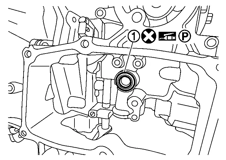
Remove lip seal from transaxle assembly .
Remove TCM mounting hexagon bolt ( 6 pieces) and then remove TCM .
CAUTION:
Never remove any hexagon bolt other than the specified bolt ( 6 pieces).
Remove connectors of terminal assembly B from TCM and then remove TCM from transaxle assembly.
NOTE:
Terminal assembly B connector claws are located on the upper and lower sides of the connector while connected to the TCM.
Remove gasket from TCM.
Remove fixing bolt of terminal assembly A and terminal assembly B to the case.
Press terminal assembly A into the transaxle case.
CAUTION:
Before handling terminal assembly A, clean around the exterior of it to prevent foreign materials from entering into the transaxle case.
Disconnect harness connector from terminal assembly A .
Disconnect harness connector of terminal assembly B from the electric oil pump.
Remove terminal assembly B.
Remove electric oil pump bracket mounting bolts .
Remove electric oil pump mounting bolts and then remove electric oil pump and terminal assembly A from transaxle assembly.
NOTE:
Take out electric oil pump from the opening for installing TCM.
Remove electric oil pump bracket from electric oil pump.
Remove electric oil pump gasket .
Remove Terminal assembly A mounting bolts and then remove Terminal assembly A from electric oil pump.
Place CVT with the converter housing side as the top.
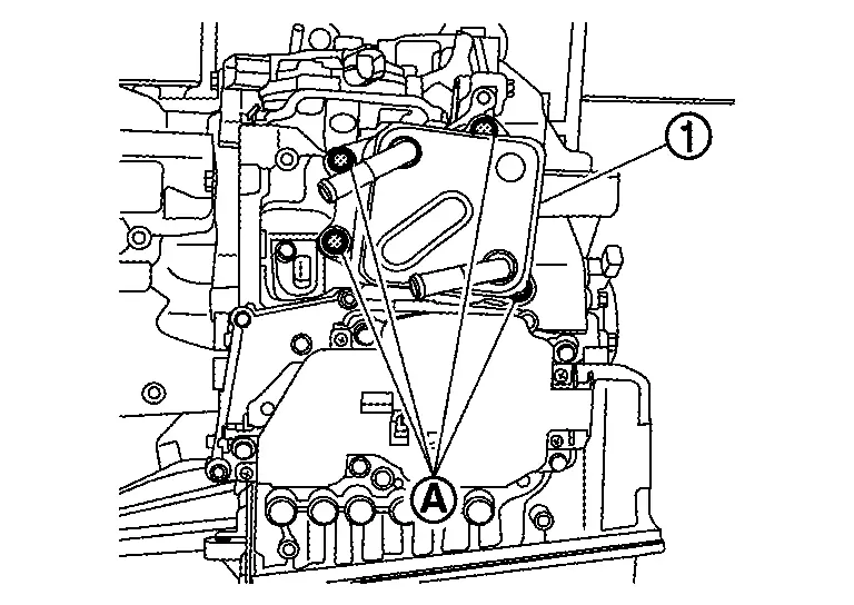
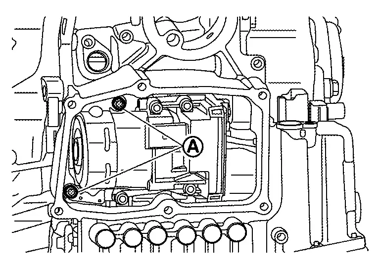
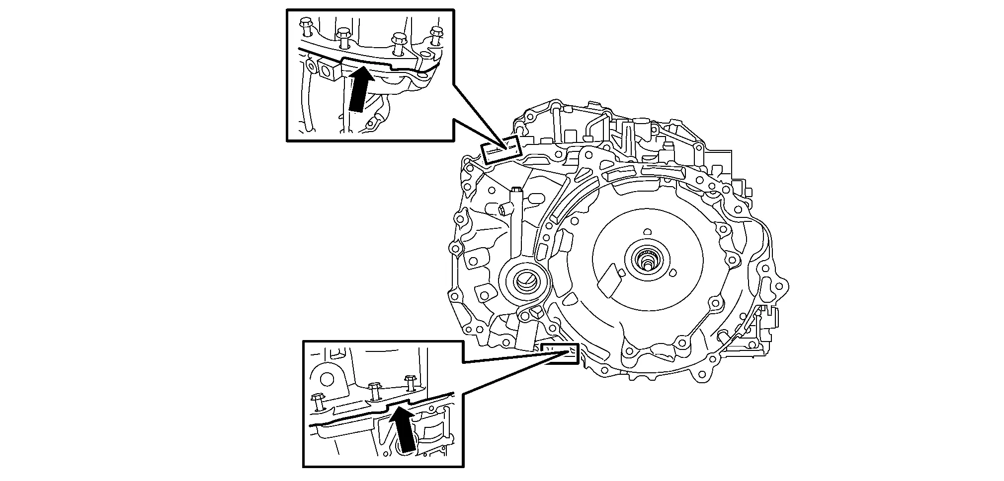
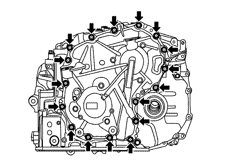
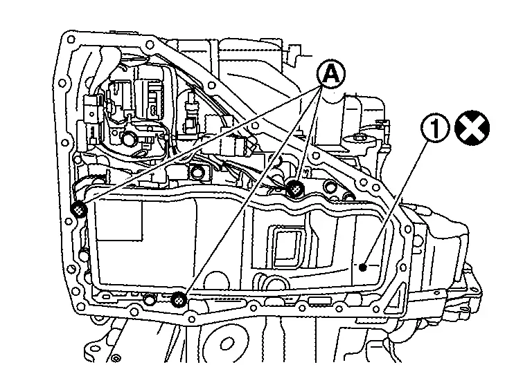
Remove converter housing mounting bolts ( 22 pieces).
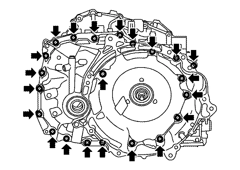
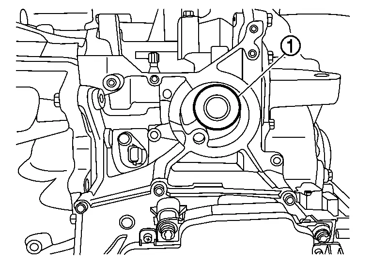
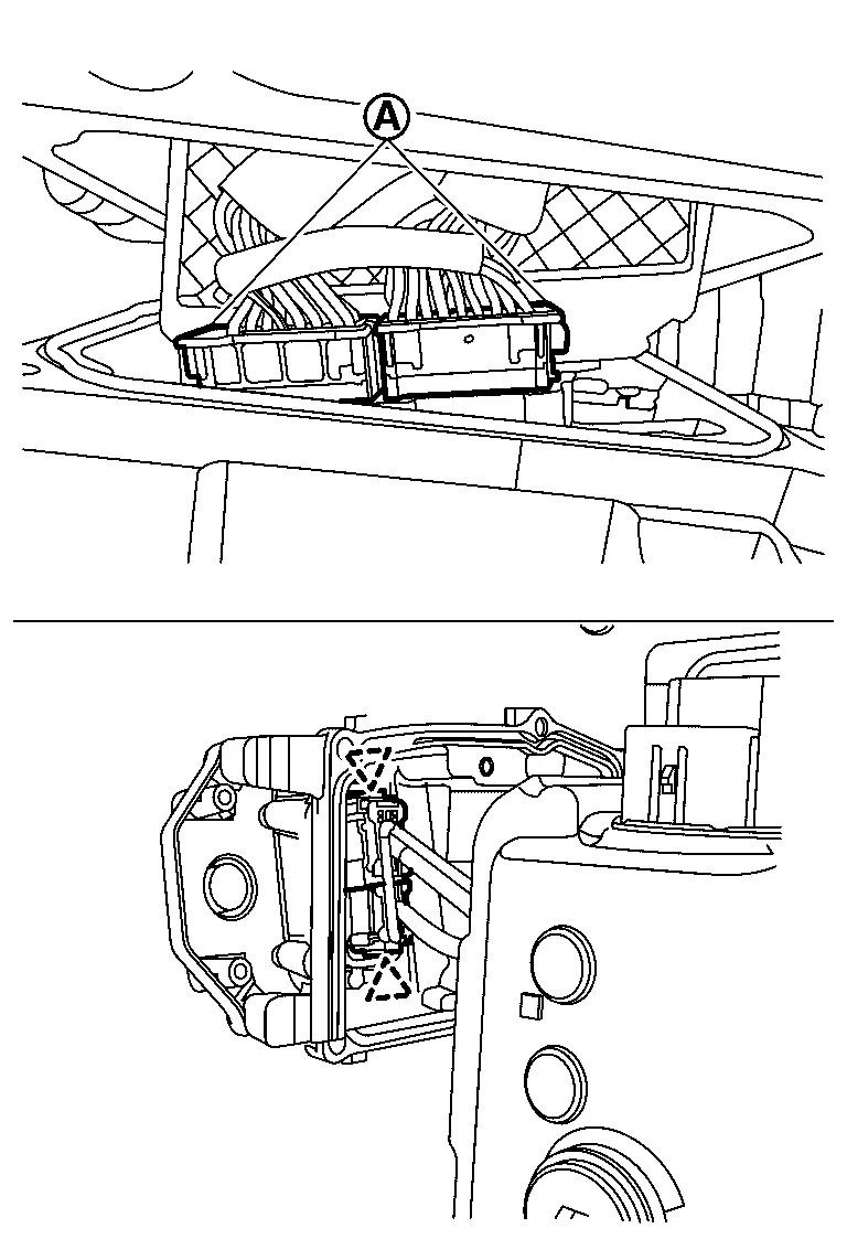
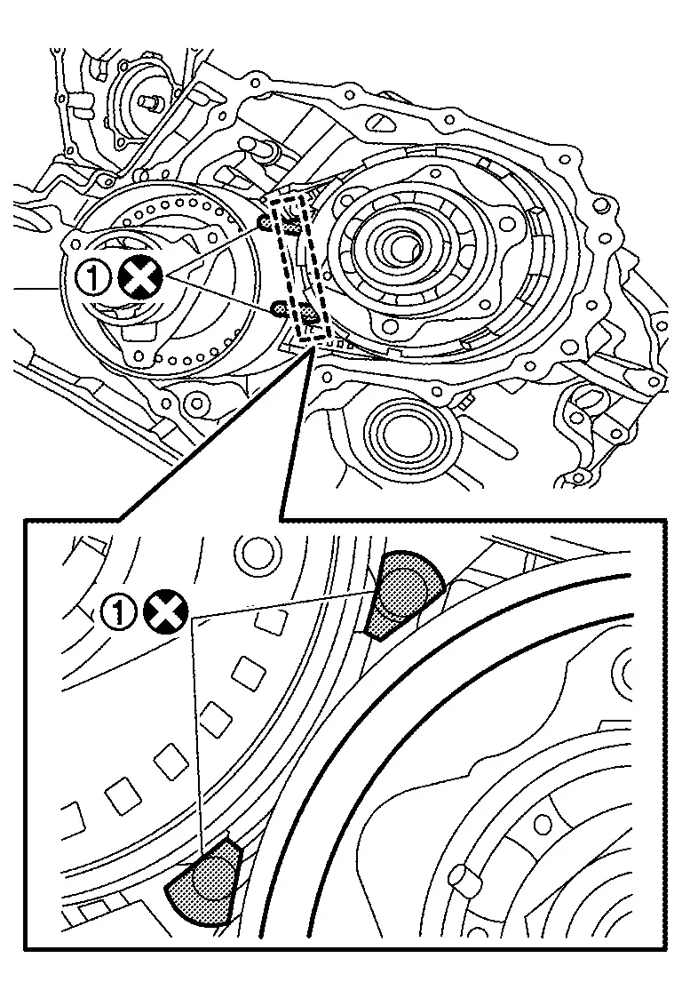
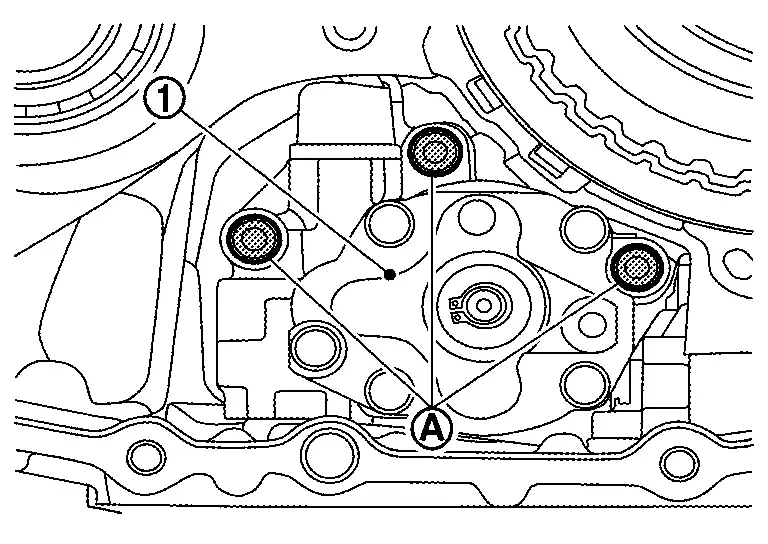
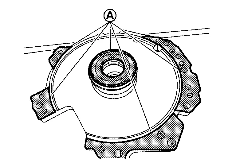
Remove converter housing by applying slide hammer [SST: KV315J0610
(NI-25721-A) ], slide hammer nut and bolt kit [SST: KV315J0630
(NI-50255-UPD)] and J hook case separator [SST: KV315J0620 (NI-51923)]
to two positions with arrow marks ( ).
Remove mounting bolt ( 3 pieces) remove the baffle plate C from the converter housing.
Check that retaining pin of manual shaft locates on the original position.
Remove reduction gear assembly and differential assembly together.
CAUTION:
Handle parts with care. Never reuse damaged parts, if dropped.
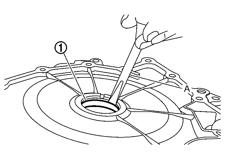
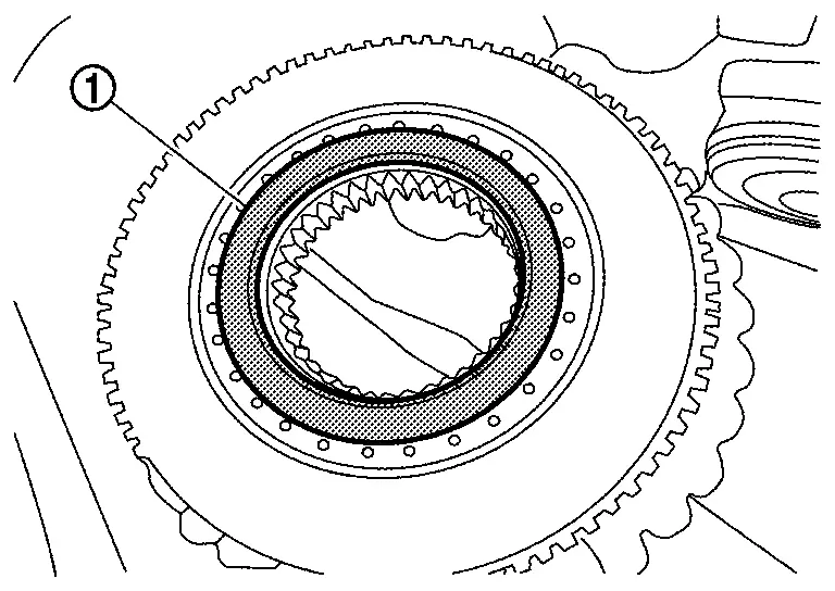
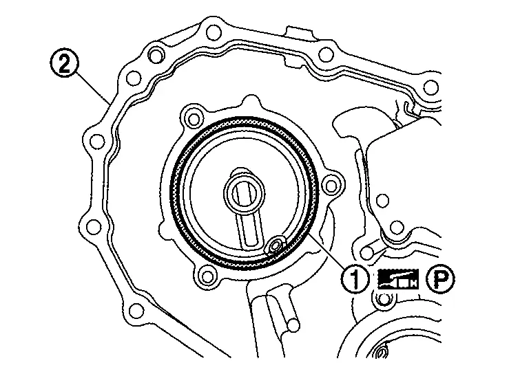
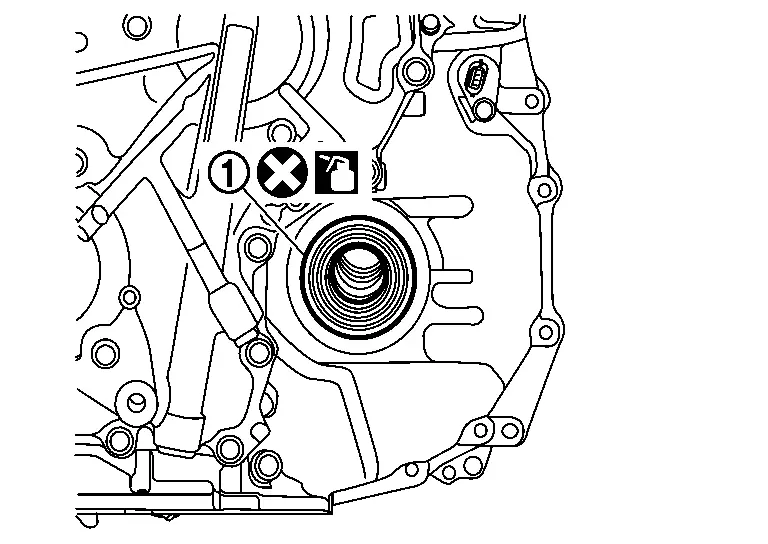
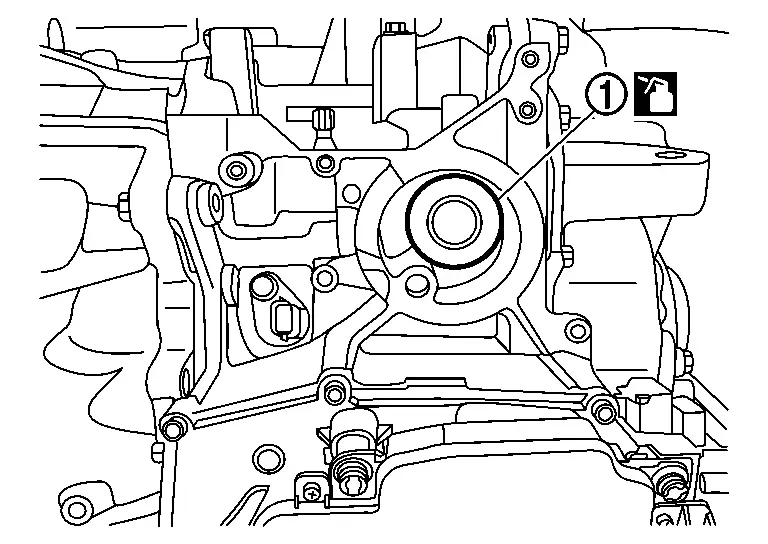
Remove converter housing oil seal from converter housing using a suitable tool .
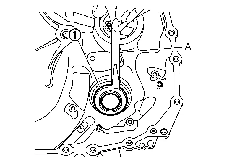
Remove differential oil seal from converter housing using a suitable tool .
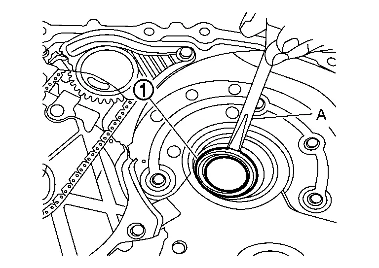
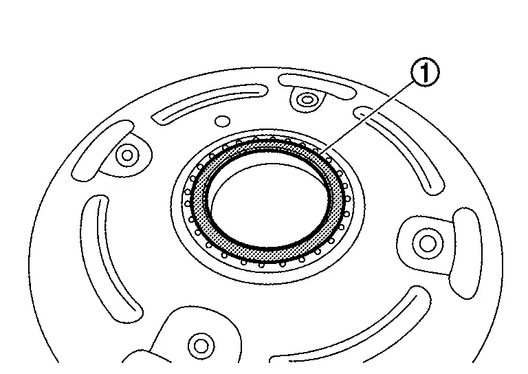
Remove differential oil seal from transaxle assembly using a suitable tool .
Remove mounting bolts of baffle plate A and then remove baffle plate A .
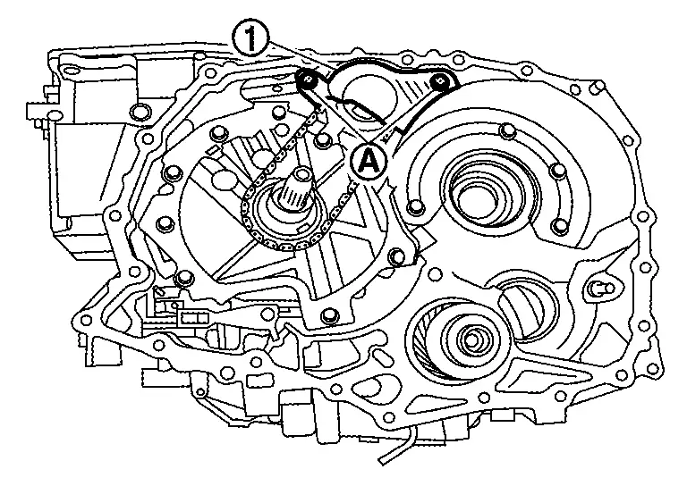
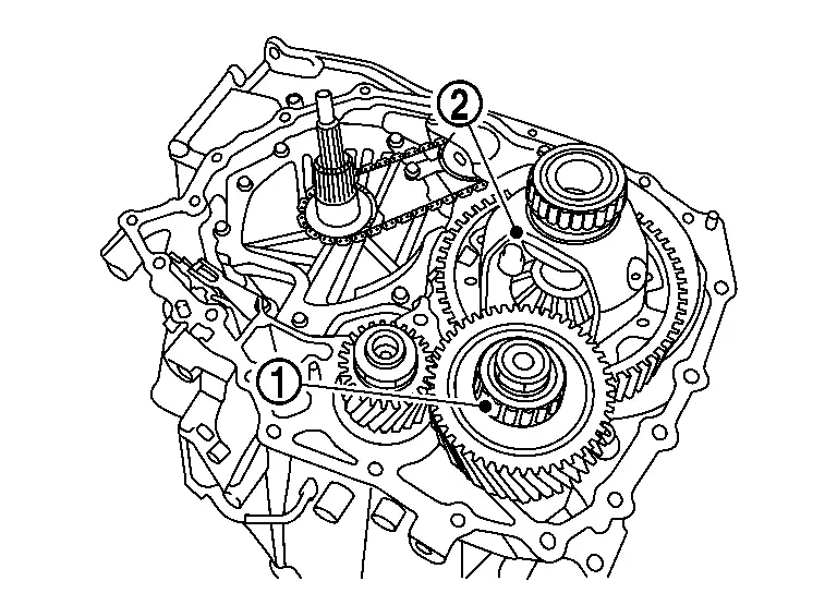
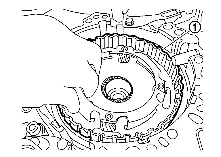
While expanding snap ring of the oil pump with snap ring pliers, lift driven sprocket and remove it.
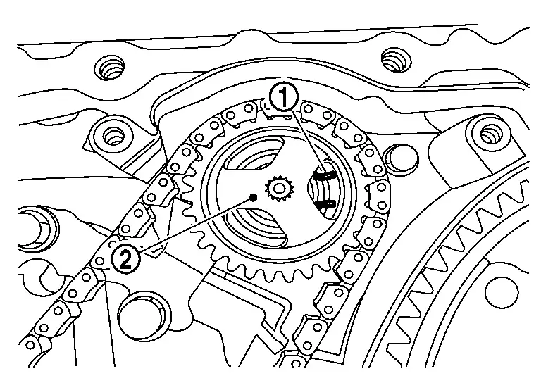
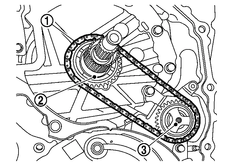
Remove chain , drive sprocket and driven sprocket all together.
Remove mounting bolts ( 7 pieces) of oil pump bracket and baffle plate B and then remove baffle plate B and oil pump bracket .
Remove oil pump snap ring .
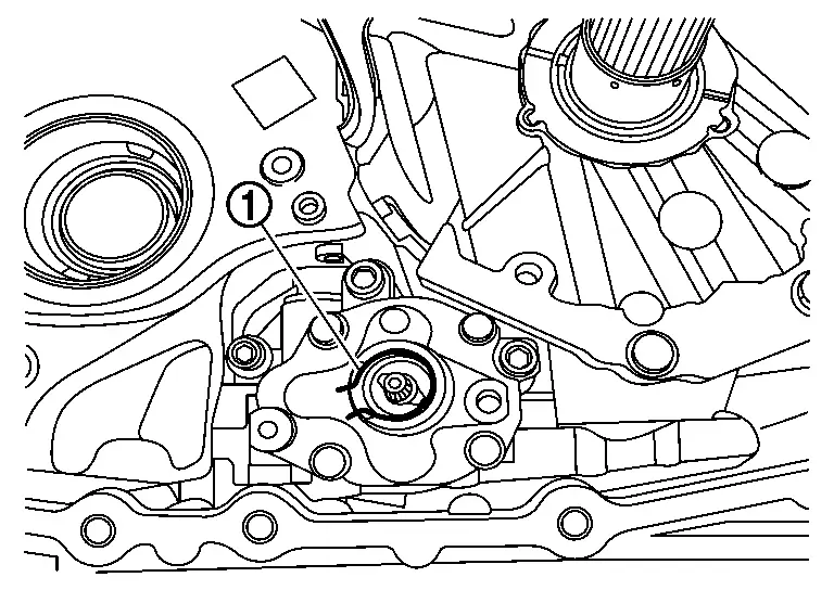
Remove oil pump mounting bolt .
CAUTION:
Remove O-ring because it cannot be reused.
Remove oil pump mounting bolts and then remove oil pump .
Remove thrust washer .
Remove mounting bolts ( 7 pieces) of dummy cover and baffle plate D, and then remove baffle plate D and dummy cover .
CAUTION:
-
Lift the dummy cover only.
-
Never lift input shaft because it causes lifting clutch pack assembly out.
-
Never remove lathe cut seals
from dummy cover. These seals will be reused.
Remove thrust bearing from forward clutch assembly.
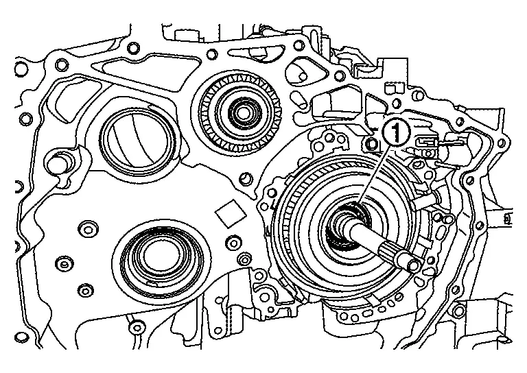
Remove forward clutch assembly from transaxle case.
CAUTION:
Never handle lathe cut seals on the input shaft when removing clutch assembly. These seals will be reused.
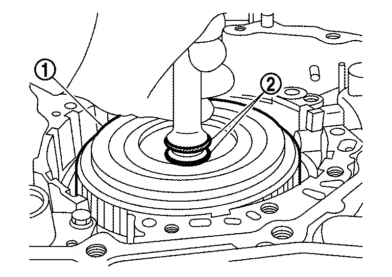
Remove thrust bearing which exists between forward clutch assembly and sun gear.
NOTE:
The thrust bearing has two sides. Memorize or take a note of the original surface before removing for assembling procedure.
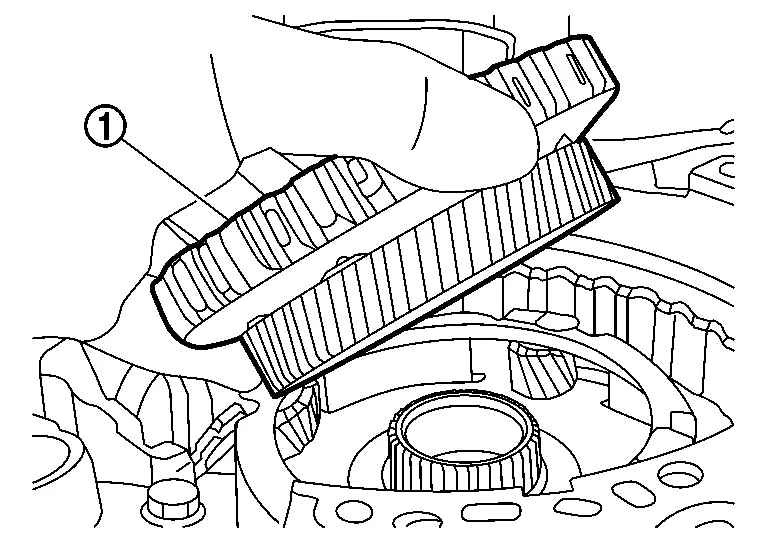
Remove sun gear from planetary carrier.
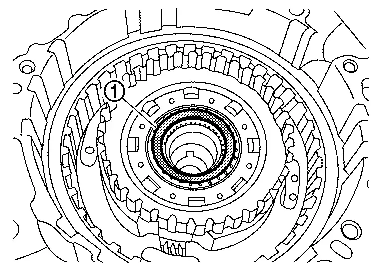
Remove thrust bearing which exists on primary pulley side of sun gear.
NOTE:
The thrust bearing has two sides. Memorize or take a note of the original surface before removing for assembling procedure.
Remove planetary carrier from transaxle case.
Remove thrust bearing from planetary carrier.
NOTE:
-
The thrust bearing has two sides. Memorize or take a note of the original surface before removing for assembling procedure.
-
Thrust bearing may remain on the transaxle case.
Thoroughly clean the mating surfaces of the transaxle case and torque converter housing.
NOTE:
A plastic scraper can be used.
CAUTION:
-
Never use sanding discs, similar abrasive tools, or metal blades.
-
Use parts cleaner or equivalent solvent and lint-free paper only.
-
Make sure the parts cleaner or solvents used are compatible with local regulations.
-
Prevent debris from entering in the CVT.
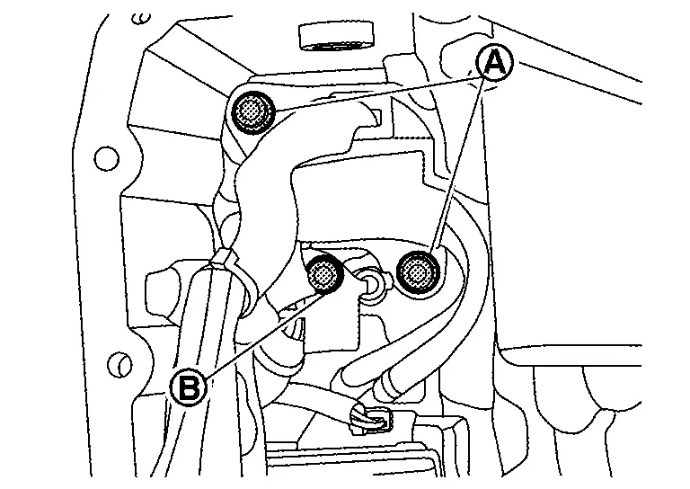
Make sure rust and foreign materials have been cleaned off of dowel pins and receiving holes .
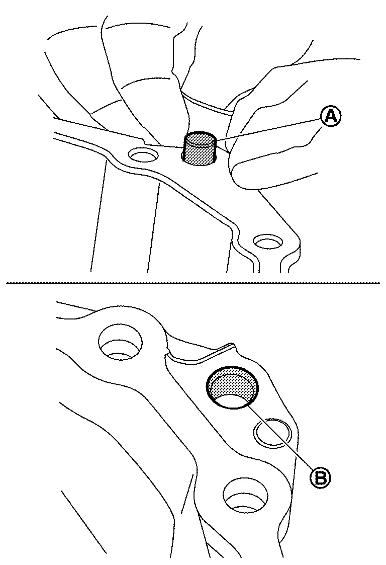
NOTE:
Use small wire brush or similar tool at the inside surface of dowel pin holes. Never scrape transaxle case mating surfaces.
Clean around oil filter and hydraulic circuits with parts cleaner and compressed air
WARNING:
Wear eye and face protection when using compressed air and cleaning fluid.
CAUTION:
-
Regulate air pressure up to a maximum of 517 kPa (5.27 kg/cm2, 75 psi).
-
Prevent foreign materials from entering the CVT.
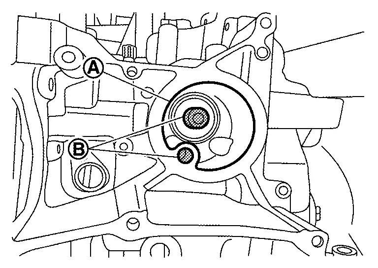
While cleaning around CVT oil warmer and hydraulic circuit with parts cleaner and blowing air.
Check hole for blowing air.
CAUTION:
When blowing air, be careful not to get foreign materials in the eyes.
While cleaning mating surface of control valve and control valve hydraulic circuits with parts cleaner and blowing air.
Check holes for blowing air.
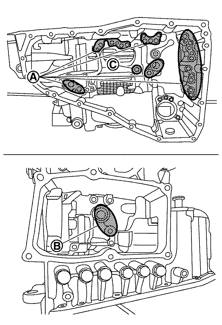
CAUTION:
-
When blowing air, be careful not to get foreign materials in the eyes.
-
Never blow air in the clutch circuit
.
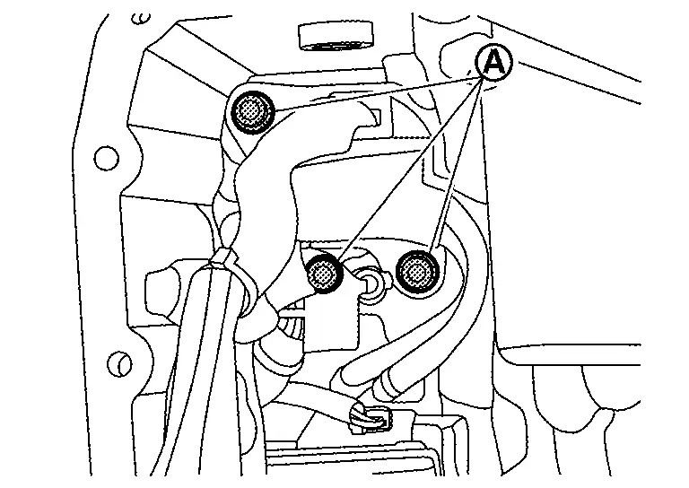
Clean hydraulic circuits of converter housing with parts cleaner and blowing air.
Check holes for blowing air.
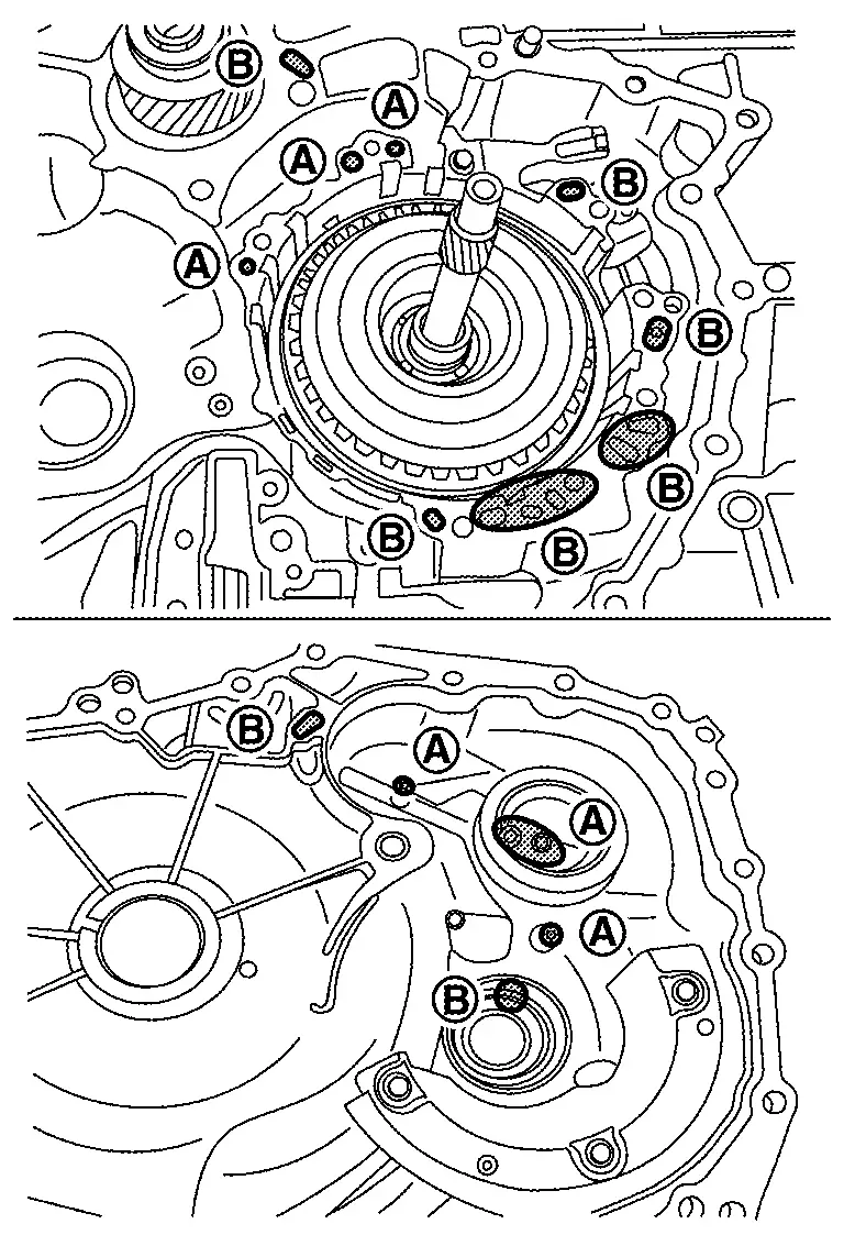
CAUTION:
When blowing air, be careful not to get foreign materials in the eyes.
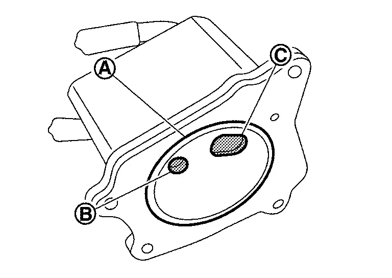
Clean hydraulic circuit of dummy cover with parts cleaner and blowing air.
Check holes for blowing air.
CAUTION:
When blowing air, be careful not to get foreign materials in the eyes.
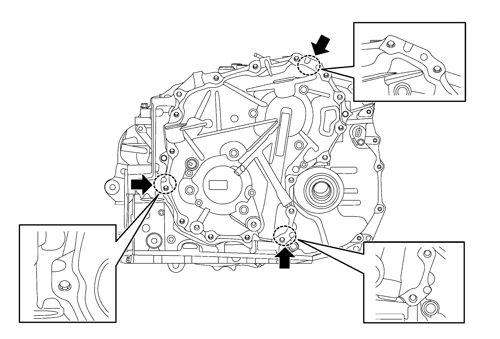
Temporarily install converter housing to transaxle case by using only three of old converter housing mounting bolts to tighten them in a triangular shape.
NOTE:
Two bolts are oppositely tightened.
Temporarily install converter housing to transaxle case by using only four of the old converter housing mounting bolts to tighten them in a square shape.
Place transaxle assembly with converter housing side as the bottom.
Remove the temporarily fixed oil pan.
Rotate the primary pulley by hand to check the pulley's rotational characteristics.
CAUTION:
Never place fingers between the pulley and the transaxle case .
NOTE:
Memorize the pulley's rotational characteristics.
This is used as a reference after the sub assembled new side cover, pulleys and belt were installed.
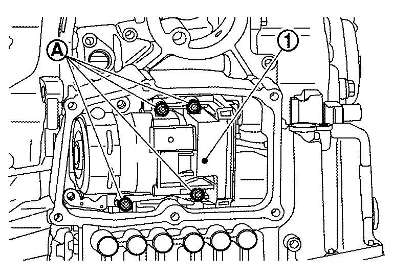
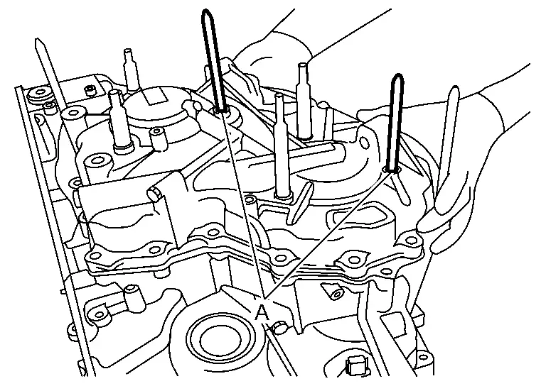
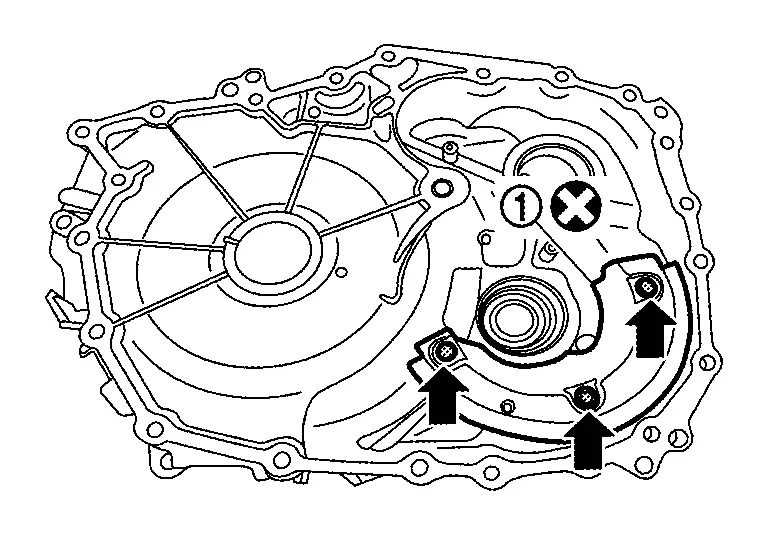
Remove side cover mounting bolts (17 pieces).
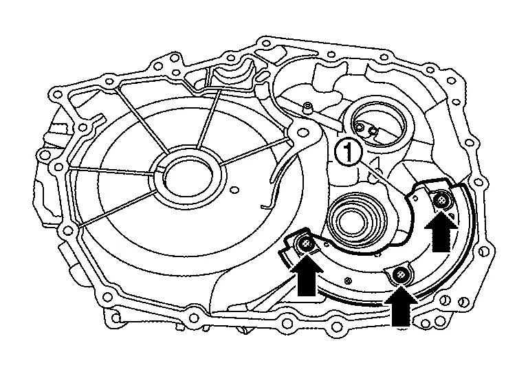
Remove pulley retainer mounting bolts (6 pieces).
Remove side cover by applying slide hammer [SST: KV315J0610
(NI-25721-A) ], slide hammer nut and bolt kit [SST: KV315J0630
(NI-50255-UPD)] to three positions with arrow marks ().
Remove lubrication caps .
CAUTION:
Never reuse the lubrication cap.
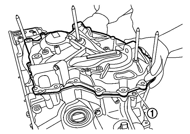
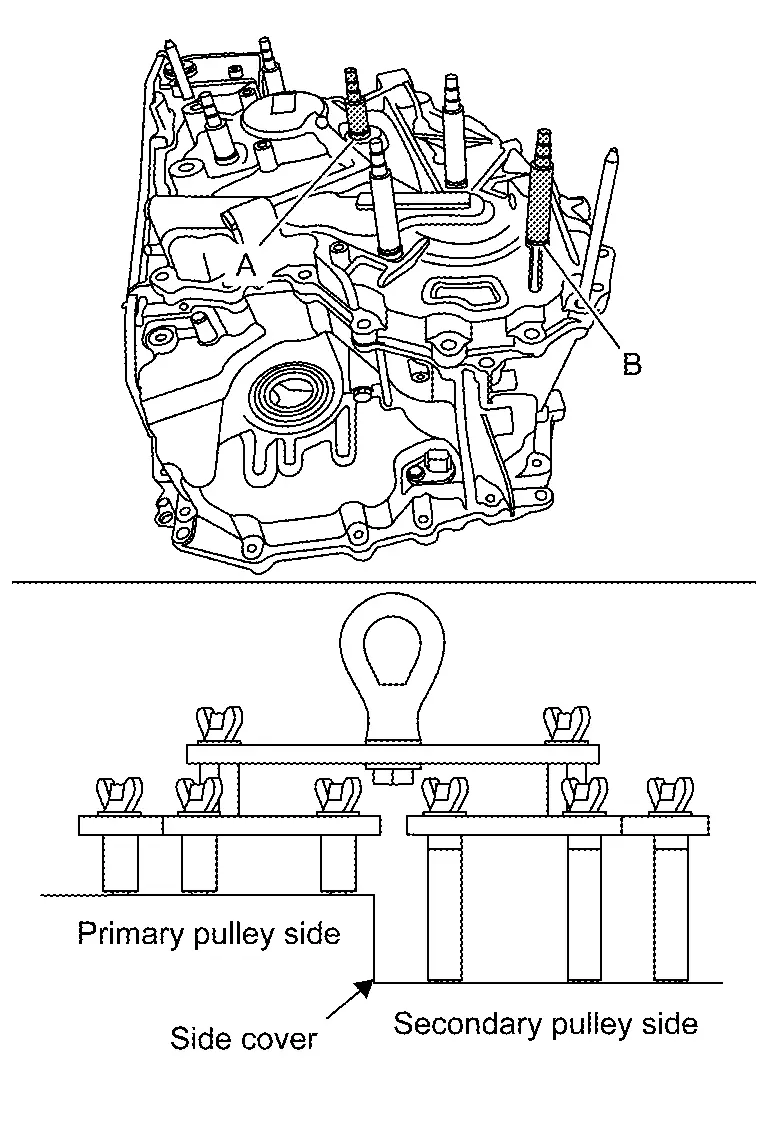
Attach the locator guide pin (SST: NI-53066) to the specified bolt holes .
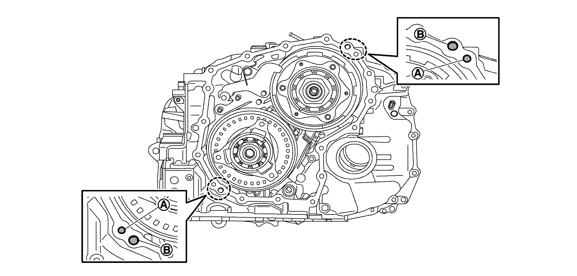
NOTE:
Guide pins must be placed next to dowel pins .
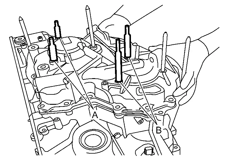
Install pulley bracket guide pin [SST: KV31500300 (NI-52272)] to primary pulley bearing retainer and secondary pulley retainer .
CAUTION:
Be careful not to let guide pin to touch the bottom.
Rotate each pulley bracket to align with holes and assembly guide pins, pulley bracket [SST: KV31500300 (NI-52272)] in the transaxle case .
|
: Align holes |
Install side cover .
NOTE:
When installing side cover, insert parking rod to parking pawl area .
CAUTION:
Check that manual shaft is 'N' position.
Install medium and long shafts of CVT universal lifting fixture [KV315J0100 (NI-52082-A)].
Remove guide pins from the pulley bracket [SST: KV31500300 (NI-52272)].
Install medium and long shafts of CVT universal lifting fixture [SST:KV315J0100 (NI-52082-A)].
Install CVT universal lifting fixture [KV315J0100 (NI-52082-A)] to bearing retainer mounting hole.
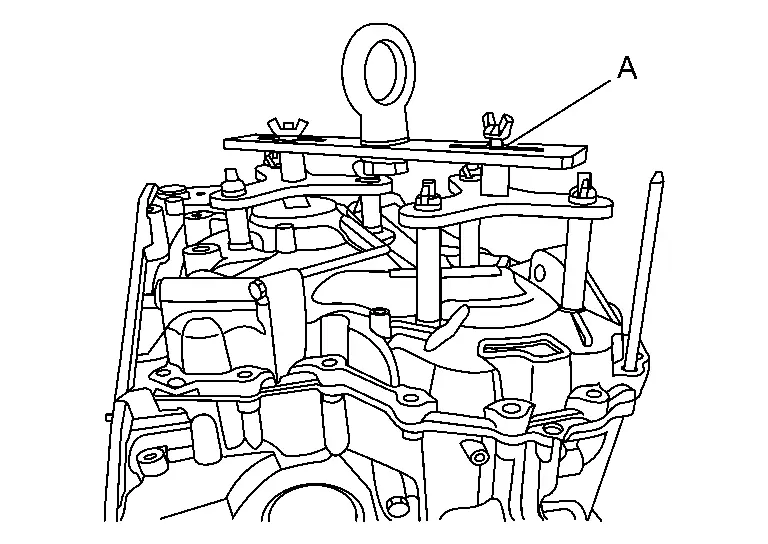
CAUTION:
Install CVT universal lifting properly.
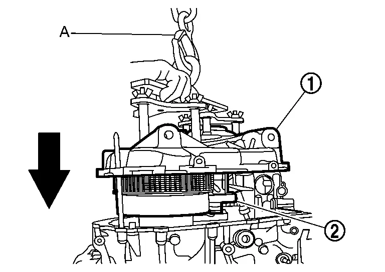
While lifting CVT universal lifting with crane , side cover , belt and pulleys as a unit.
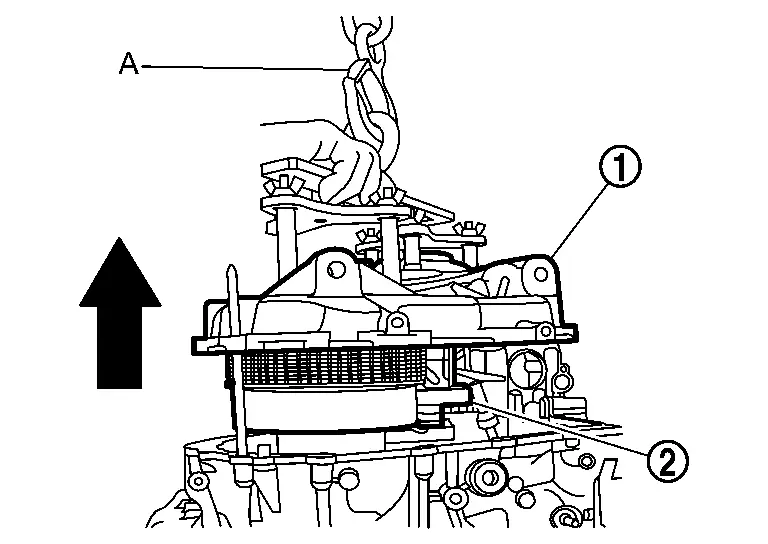
Remove O-ring .
Completely remove old liquid gasket from transaxle case.
ASSEMBLY
Install CVT universal lifting fixture [SST:KV315J0100 (NI-52082-A)] to new side cover, belt and pulleys kit.
CAUTION:
As soon as removing a bearing retainer mounting bolt, install a shaft of universal lifting.(Exchange one by one. If all bearing retainer mounting bolts are removed at once, CVT universal lifting may not be installed well.)
While lifting CVT universal lifting with crane , install side cover , belt and pulleys all together to transaxle case at the same time.
CAUTION:
-
Apply CVT fluid to primary front bearing and secondary front bearing before assembling.
-
Never drop parts with care. If dropped, parts may be damaged and can not be reused.
While lowering transaxle universal lifting, install pulley sub-assembly to CVT case.
NOTE:
When installing side cover, insert parking rod to parking pawl area .
CAUTION:
Check that manual shaft is 'N' position.
Remove CVT universal lifting .
Remove side cover by applying slide hammer [SST: KV315J0610
(NI-25721-A) ], slide hammer nut and bolt kit [SST: KV315J0630
(NI-50255-UPD)] and J hook case separator [SST: KV315J0620 (NI-51923)]
to three positions with arrow marks ().
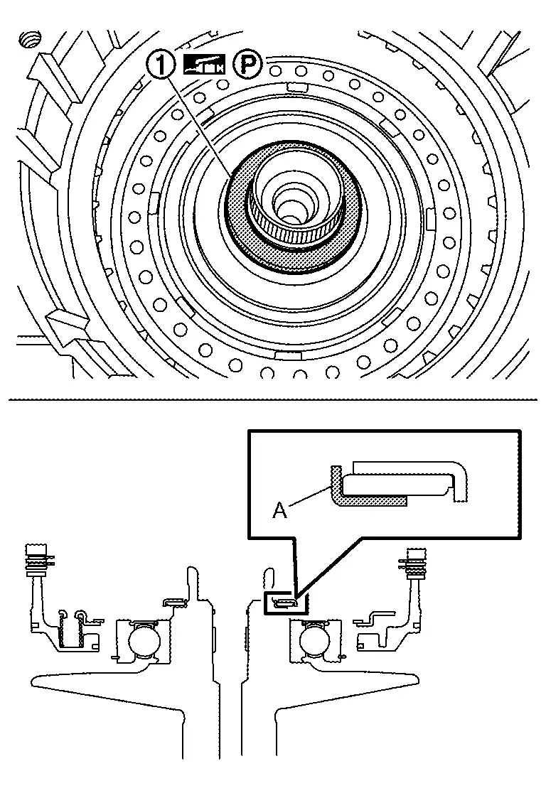
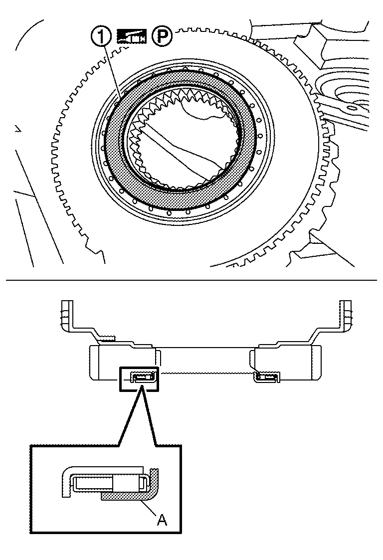
Install lubrication caps .
CAUTION:
-
Never reuse the lubrication cap.
-
Assemble the lubrication cap
as shown in the figure.
Install O-ring .
CAUTION:
-
Never reuse the O-ring.
-
Apply petroleum jelly to O-ring.
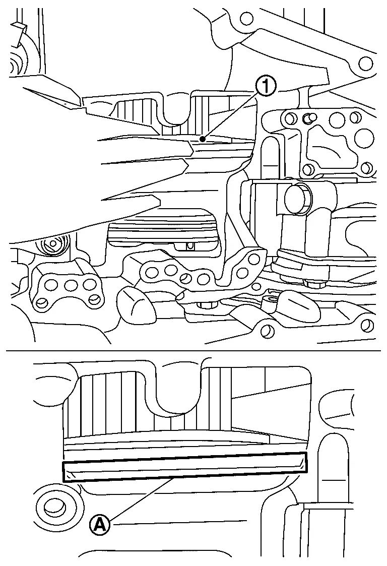
Apply Loctite 5460 on the transaxle case installation surface of the side cover.
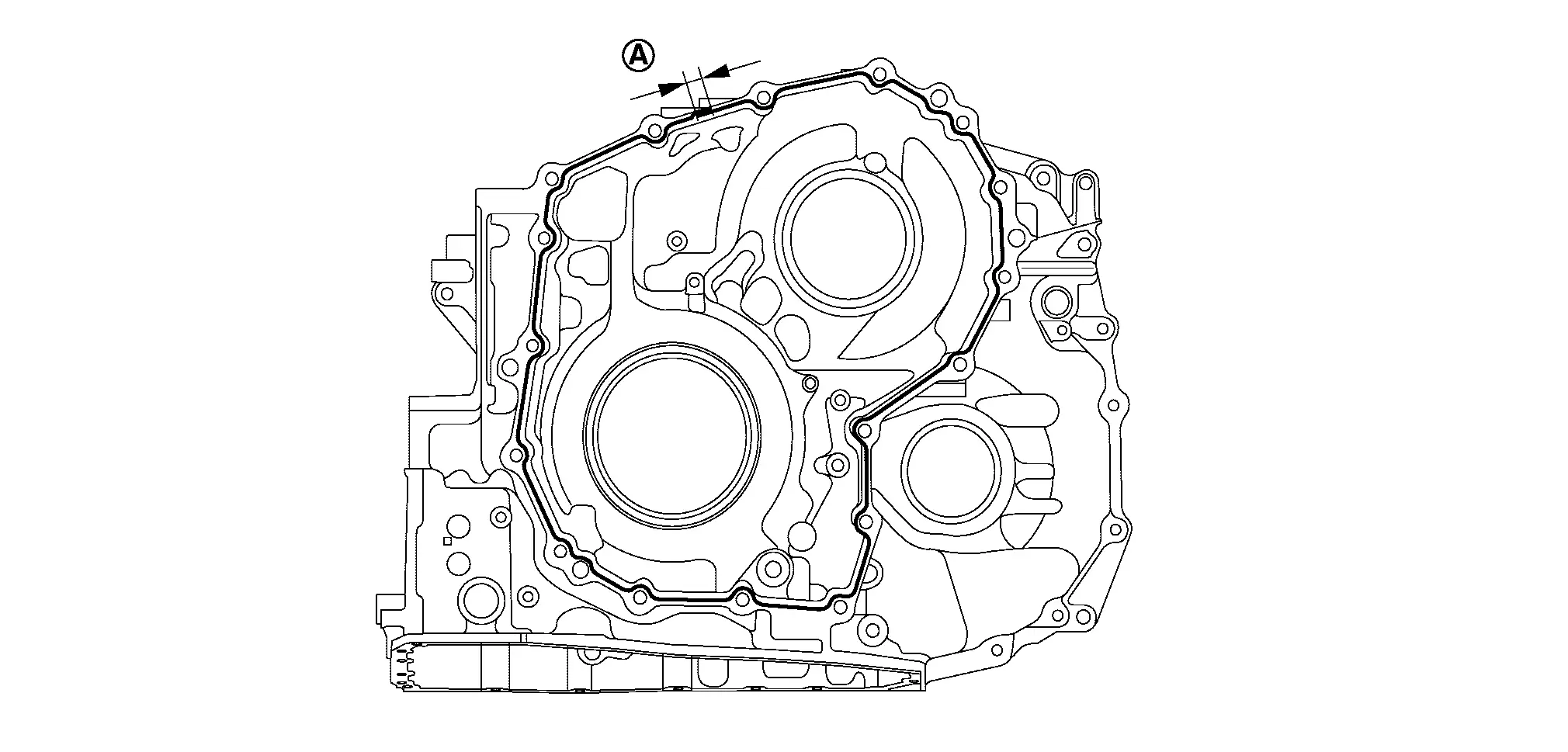
CAUTION:
-
Completely remove all moisture, oil and old sealant, etc. from the transaxle case and converter housing mounting surfaces.
-
The sealant width is 2 - 3 mm (0.08 - 0.12 in).
-
Check that the starting point and the ending point are about the middle between the bolts. The overlap both ends of the bead by 3 - 5 mm (0.12 - 0.20 in)
. -
Be careful not to contact or contaminate the sealant. If the sealant has been disturbed or contaminated in any way before case assembly, thoroughly clean the mating surfaces of the transaxle case.
Install pulley bracket guide pin [[SST: KV31500300 (NI-52272)] to primary pulley bearing retainer and secondary pulley retainer , and then install locator guide pin (SST: NI-53066) of side cover.
Rotate each pulley bracket to align with holes and assembly guide pins, pulley bracket [SST: KV31500300 (NI-52272)] in the transaxle case .
|
: Align holes |
Check that the shim on the bottom side of the side cover .
NOTE:
Apply petroleum jelly as needed to keep the shim in place while lowering the side cover to the transaxle case.
Install side cover .
NOTE:
-
When installing side cover, insert parking rod
to parking pawl area . -
Clean and degrease mating surface of the side cover with case.
CAUTION:
-
Check that manual shaft is 'N' position.
-
Never touch mating surfaces after cleaning and degreasing.
Tighten side cover mounting bolts to the specified torque in numerical order shown in the figure. Refer to Exploded View.
CAUTION:
-
Never reuse the side cover mounting bolts.
-
Apply CVT fluid to the mounting bolts.
Install O-ring to pulley retainer bolt.
CAUTION:
-
Never reuse the O-ring.
-
Never reuse the pulley retainer bolt.
Before removing guide pin, install bearing retainer mounting bolts (4 pieces) and temporarily tighten them. Then, pull out guide pin, install bearing retainer mounting bolts (2 pieces), and temporarily tighten them.
Rotate the primary pulley by hand to check the pulley's rotational characteristics.
CAUTION:
Never place fingers between the pulley and the transaxle case .
NOTE:
Confirm that the characteristic is the same as previously checked at step 76 of disassembly.
Tighten bearing retainer mounting bolts ( 6 pieces) to the specified torque. Refer to Exploded View.
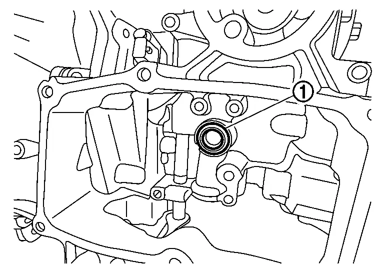
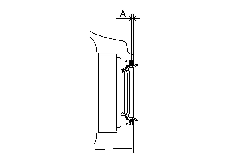
Install differential oil seal to the case with seal installer (SST: NI-52284) until it is flush.
Height or depth of differential oil seal from the surface : 0 ± 0.5 mm (0 ± 0.020 mm)
CAUTION:
-
Never reuse differential oil seal.
-
Apply the CVT fluid to the differential oil seal.
Temporarily install converter housing to transaxle case by using only four of the old converter housing mounting bolts to tighten them in a square shape.
Place CVT with the converter housing side as the top.
Remove temporarily installed converter housing.
Remove the temporarily fixed oil pan.
Install oil pump and then tighten oil pump mounting bolts to the temporary torque.
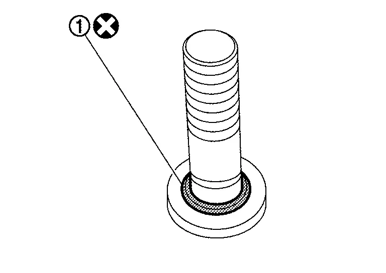
Install O-ring to oil pump mounting bolt.
CAUTION:
-
Never reuse the O-ring.
Tighten oil pump mounting bolt to the temporary torque.
Tighten oil pump mounting bolts to thespecified torque. Refer to Exploded View.
Tighten oil pump mounting bolt to the specified torque. Refer to Exploded View.
Install oil pump snap ring .
Install thrust bearing to the transaxle assembly.
NOTE:
-
Make sure thrust bearing is installed in the correct direction.
-
Apply petroleum jelly to the thrust bearing to hold it in place on the primary pulley.
-
Assemble with the colored surface
side down.
Install planetary carrier to the transaxle assembly.
Install thrust bearing to sun gear.
NOTE:
-
Make sure thrust bearing is installed in the correct direction.
-
Apply petroleum jelly to the thrust bearing to hold it in place on the sun gear.
-
Assemble so that the colored surface
side can be seen.
Install the sun gear to the transaxle assembly.
Install thrust bearing to sun gear.
NOTE:
-
Make sure thrust bearing is installed in the correct direction.
-
Apply petroleum jelly to the thrust bearing to hold it in place on the sun gear.
-
Assemble so that the colored surface
side can be seen.
Install forward clutch assembly to the transaxle assembly.
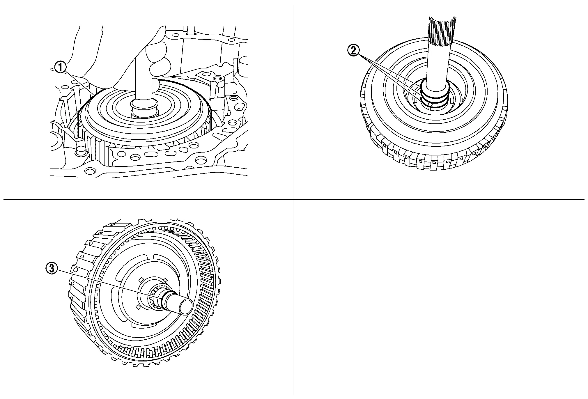
NOTE:
-
Check that the lathe cut seals
are in the specified positions before clutch assembly installation. -
Check that the lathe cut seal
is in the specified position before clutch assembly installation. -
Lathe cut seal must be in its appropriate slot. Carefully reposition the seal as necessary.
Make sure that clutch assembly is completely entered.
-
The forward clutch is 2-3 mm (0.08 - 0.12 in) below the oil pump cover surface.
-
If the gap is more than 2-3 mm (0.08 - 0.12 in), the component parts may be improperly installed. Refer to Trouble Shooting.
-
If the gap is less than 2-3 mm (0.08 - 0.12 in), the component parts may be missing or damaged.
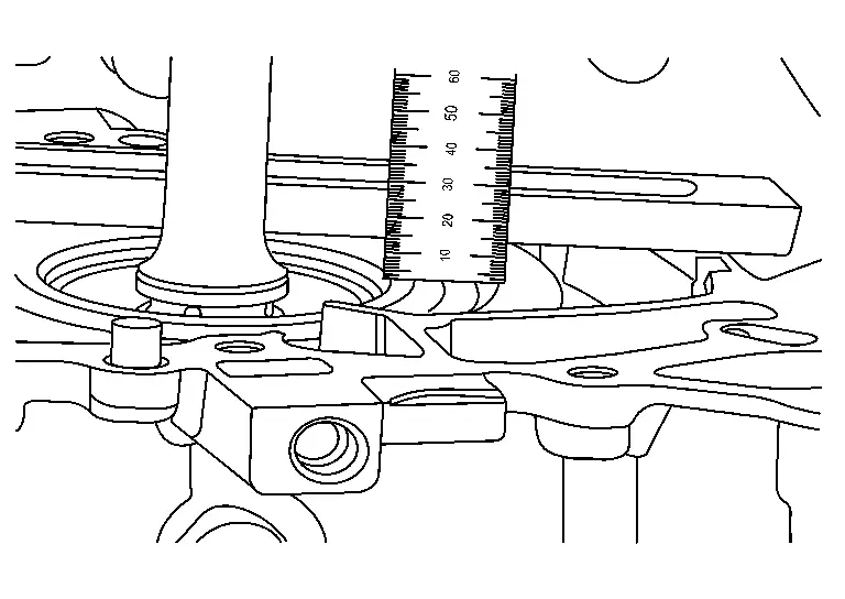
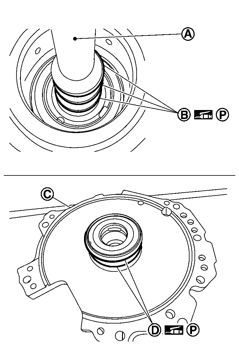
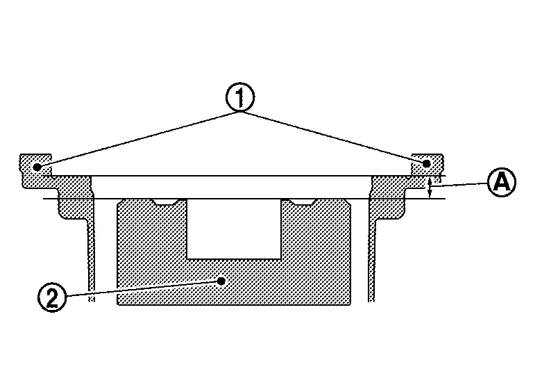
Calculate total end play with the following procedure.

|
: Dummy cover |
|
: Forward clutch drum |
|
: Thrust bearing |
|
: Transaxle case |
Measure the average distance  from the dummy cover installation surface of the transaxle case to the needle bearing installation surface of the forward clutch drum .
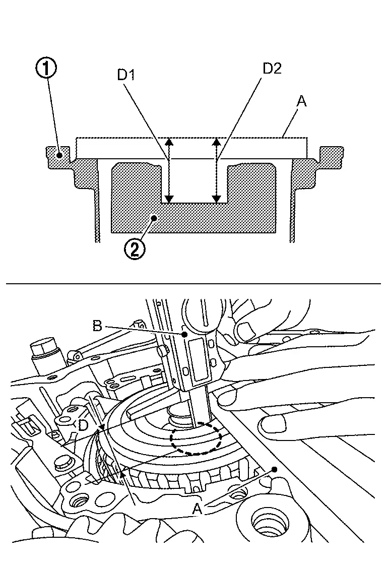
| Average distance |
: (D1 + D2)/2 |
| A | : Gauge block [SST: KV315J0400 (NI-50271)] |
| B | : Digital Depth Gauge [SST:KV315J0500 (NI-50272)] |
Clean the dummy cover surfaces that contact the transaxle case and thrust beaning.
CAUTION:
-
Use parts cleaner or equivalent solvent and lint-free paper only.
-
Make sure the parts cleaner or solvents used are compatible with local requlations.
Measure the distance  from the edge of the dummy cover to the installation surface on the transaxle case.
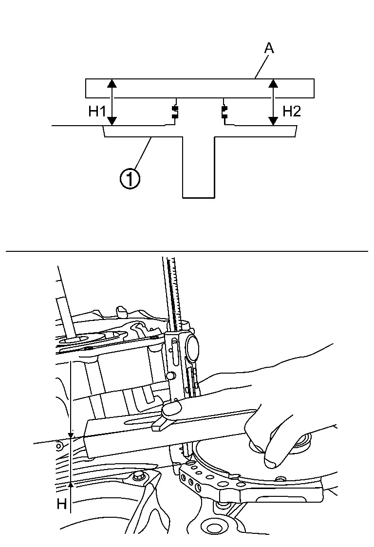
| Average distance |
: (H1 + H2)/2 |
| A | : Gauge block [SST: KV315J0400 (NI-50271)] |
Calculate the total end play with the following formula, and choose the appropriate bearing from the following table.
- = Total end play
| Total end play |
Bearing thickness |
| 3.87 - 4.06 mm | 3.57 mm |
| 4.07 - 4.24 mm | 3.75 mm |
| 4.25 - 4.41 mm | 3.93 mm |
| 4.42 - 4.59 mm | 4.1 mm |
| 4.60 - 4.77 mm | 4.28 mm |
| 4.78 - 4.93 mm | 4.46 mm |
| 4.94 - 5.10 mm | 4.61 mm |
| 5.11 - 5.29 mm | 4.79 mm |
Install the thrust bearing to the clutch assembly bore.
CAUTION:
-
Apply petroleum jelly when installing the thrust bearing .
-
Pay attention to the direction of the thrust bearing when installing it. When installing thrust bearing, its brown plate should be facing to forward clutch.
|
: Upper side |
|
: Lower side (Colored surface) |
Install dummy cover and baffle plate D .
And then tighten dummy cover and baffle plate D mounting bolts ( 7 pieces) to the specified torque. Refer to Exploded View.
CAUTION:
-
Apply petroleum jelly to the input shaft's
lathe cut seals before installing the dummy cover to the transaxle case. -
Check that the input shaft's
lathe cut seals are in the specified position. -
Lathe cut seals
(white seals) must be in their appropriate slots. Carefully reposition seals as necessary. -
Lathe cut seals
must be in specified positions during final assembly to prevent drivability issues. -
Apply petroleum jelly to the dummy cover's
lathe cut seals before installing the dummy cover to the transaxle case. -
Check that the dummy cover's lathe cut seals are in the specified positions.
-
Lathe cut seals
(white seals) must be in their appropriate slots. Carefully reposition seals as necessary. -
Lathe cut seals
must be in specified positions during final assembly to prevent drivability issues. -
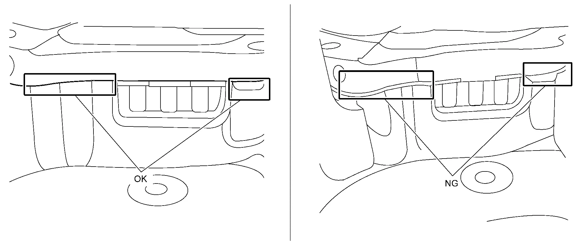
After installing dummy cover and before tightening bolts, make sure that mating surfaces of dummy cover and case are seated without any gaps.
Install baffle plate B and then tighten baffle plate B mounting bolts (5 pieces) to the specified torque. Refer to Exploded View.
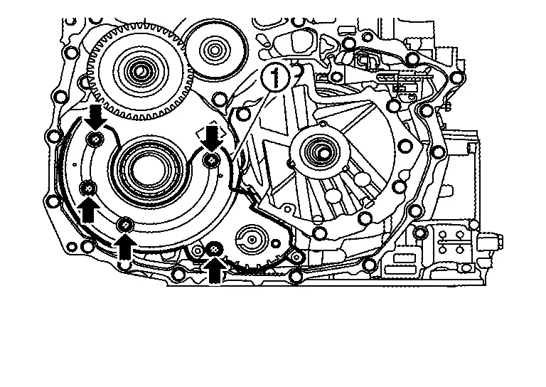
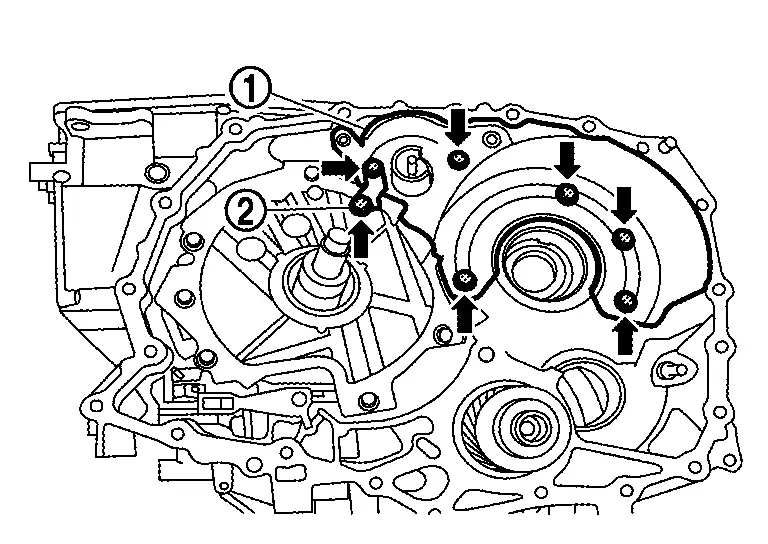
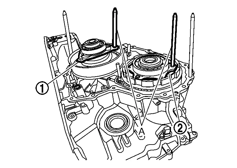
Install oil pump bracket and
then tighten oil pump bracket mounting bolts to the specified torque
each in numerical order 1 and 2 shown in the figure. Refer to Exploded
View.
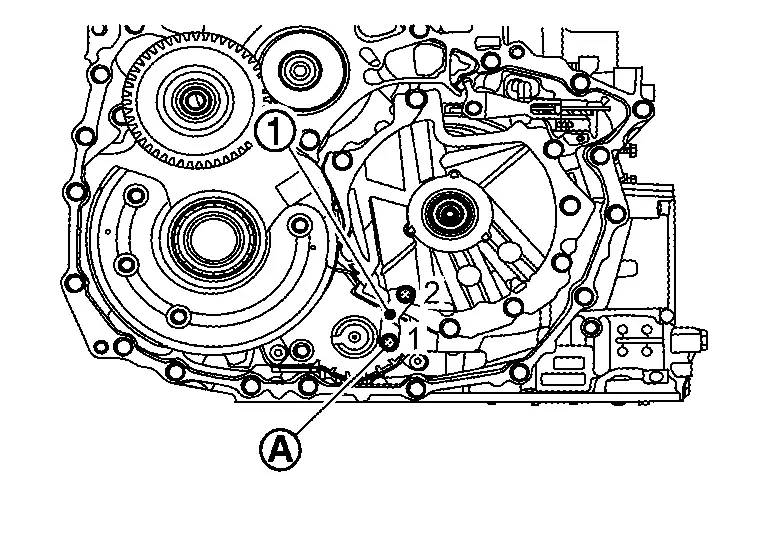
CAUTION:
As the internal thread of the oil pump bolt may be damaged, please follow the below cautions when installing bolt .
-
Do not use air or electric power tools when tightening the bolt.
-
Use hands to tighten the bolt until you feel the torque. When applying torque, slowly tighten the bolt using more then 1 second to tighten a 90 degrees angle.
Install thrust washer .
NOTE:
-
Use petroleum jelly to hold the thrust washer in place.
-
Make sure the tabs (
 ) fit into the holes.
Install chain , drive sprocket and driven sprocket all together.
While expanding snap ring of oil pump with snap ring pliers , fix driven sprocket .
CAUTION:
Lift driven sprocket and check that it does not come off.
Install baffle plate A and then tighten baffle plate A mounting bolts to the specified torque. Refer to Exploded View.
CAUTION:
Never reuse the baffle plate A.
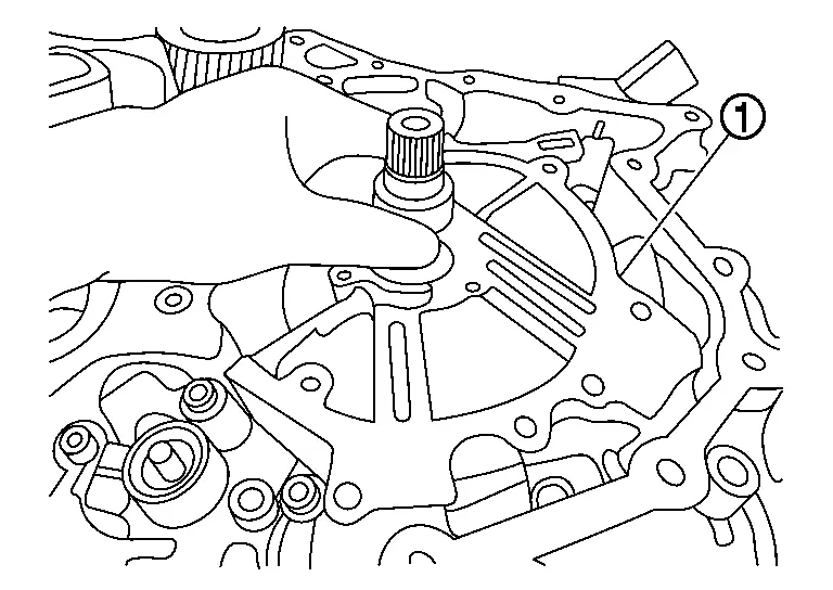
Install reduction gear assembly together with differential assembly .
CAUTION:
Handle parts with care. If dropped, parts may be damaged and can not be reused.
Check that retaining pin of manual shaft locates on the original position.
nstall baffle plate C to the converter housing and then tighten baffle plate C mounting bolts ( 3 pieces) to the specified torque. Refer to Exploded View.
CAUTION:
Never reuse baffle plate C.
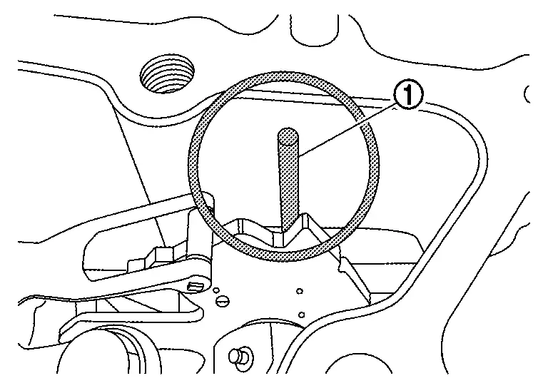
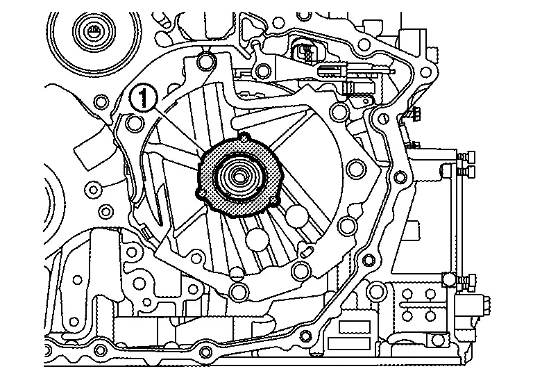
Apply Loctite 5460 on the converter housing installation surface of the transaxle case.
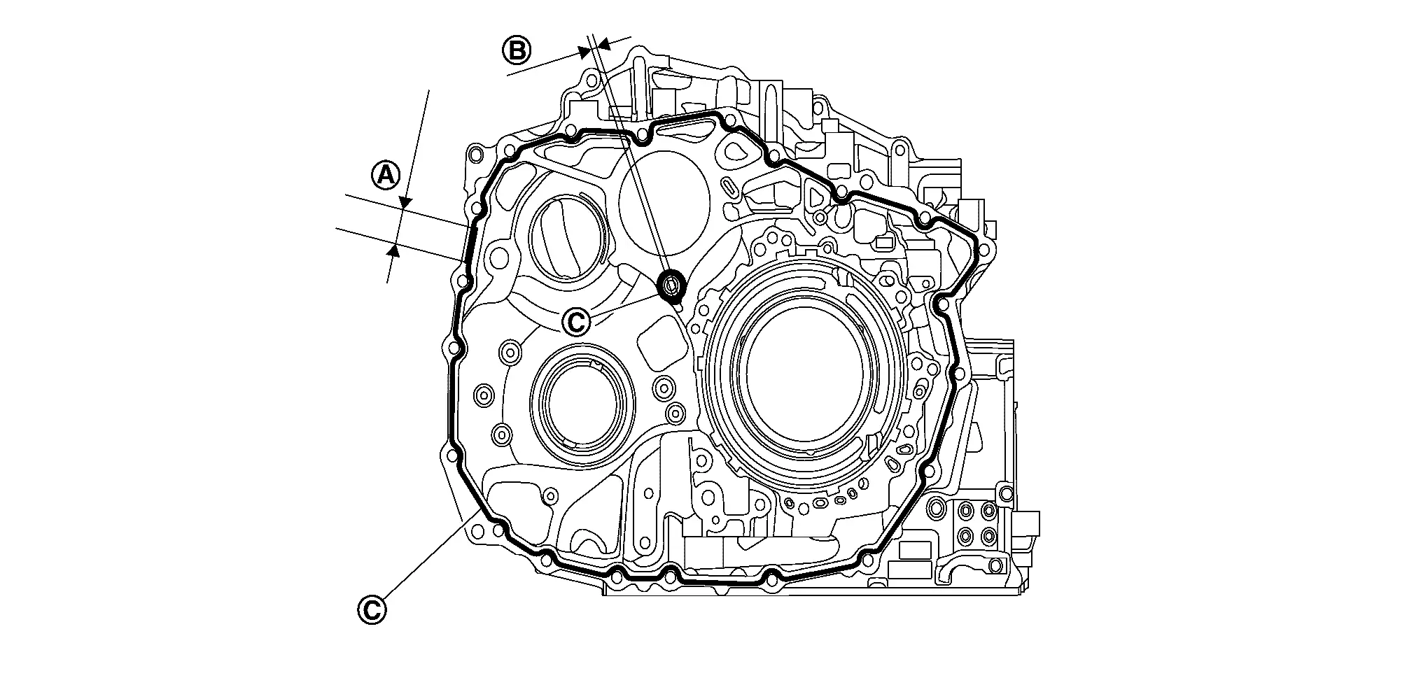
CAUTION:
-
Be sure to apply, first sealant around the center bolt hole
, and next around the mating surfaces . -
Completely remove all moisture, oil and old sealant, etc. from the transaxle case and converter housing mounting surfaces.
-
Apply sealant to this portion at first
, to prevent skipping applying sealant to this area. -
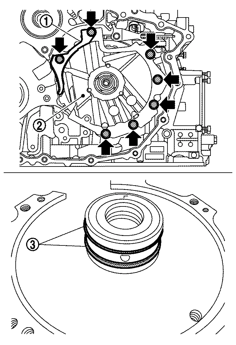
The sealant width is 2 - 3 mm (0.08 - 0.12 in).
-
Check that the starting point and the ending point are about the middle between the bolts. The overlap both ends of the bead by 25 - 30 mm (0.98 - 1.18 in)
. -
The overlap both ends of the bead by 3 - 5 mm (0.12 - 0.20 in)
.
Install converter housing.
CAUTION:
Completely remove all moisture, oil and old sealant, etc. from the transaxle case and converter housing mounting surfaces.
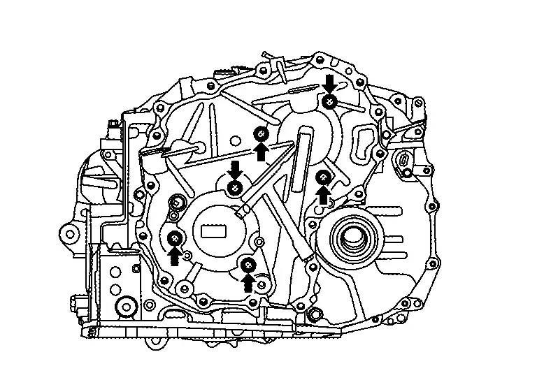
Tighten converter housing mounting bolts to the specified torque in numerical order shown in the figure. Refer to Exploded View.
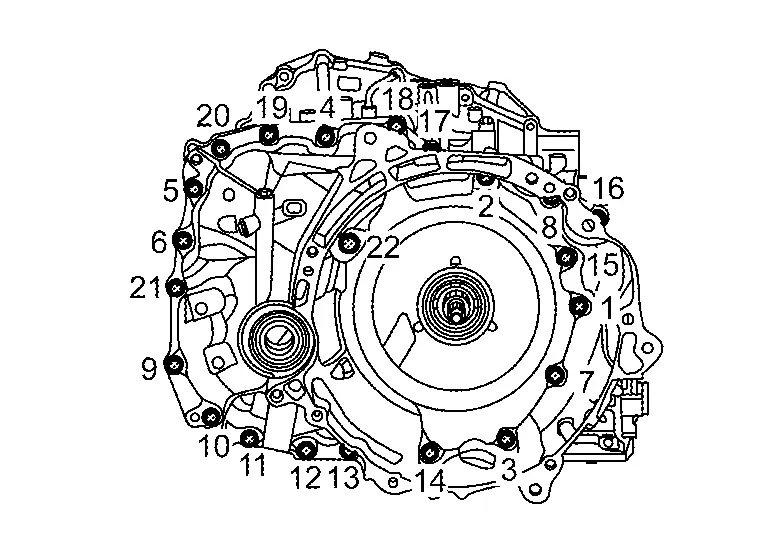
NOTE:
Apply CVT fluid to the bolts when installing.
CAUTION:
Never reuse the converter housing mounting bolts.
Install converter housing oil seal to the converter housing with seal installer (SST: NI-53062) until it is flush.
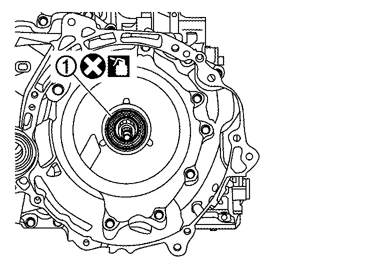
| Height or depth of converter housing oil seal from the surface |
mm (0.04±0.020 in) |
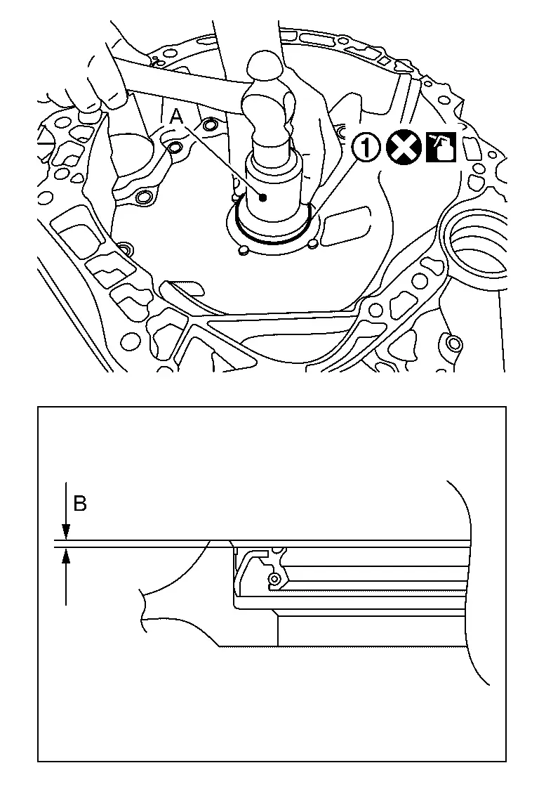
CAUTION:
-
Never reuse converter housing oil seal.
-
Apply the CVT fluid to the converter housing oil seal.
Install differential oil seal to the converter housing with seal installer (SST: NI-52283) until it is flush. (2WD models)
| Height or depth of differential oil seal from the surface | mm (0±0.020 in) |
CAUTION:
-
Never reuse differential oil seal.
-
Apply the CVT fluid to the differential oil seal.
Check that the O-ring is installed on terminal assembly A.
CAUTION:
Never reuse terminal assembly A.
Connect terminal assembly A and to electric oil pump. Tighten mounting bolts of terminal assembly A to the specified torque. Refer to Exploded View.
CAUTION:
Never install terminals in the opposite direction.
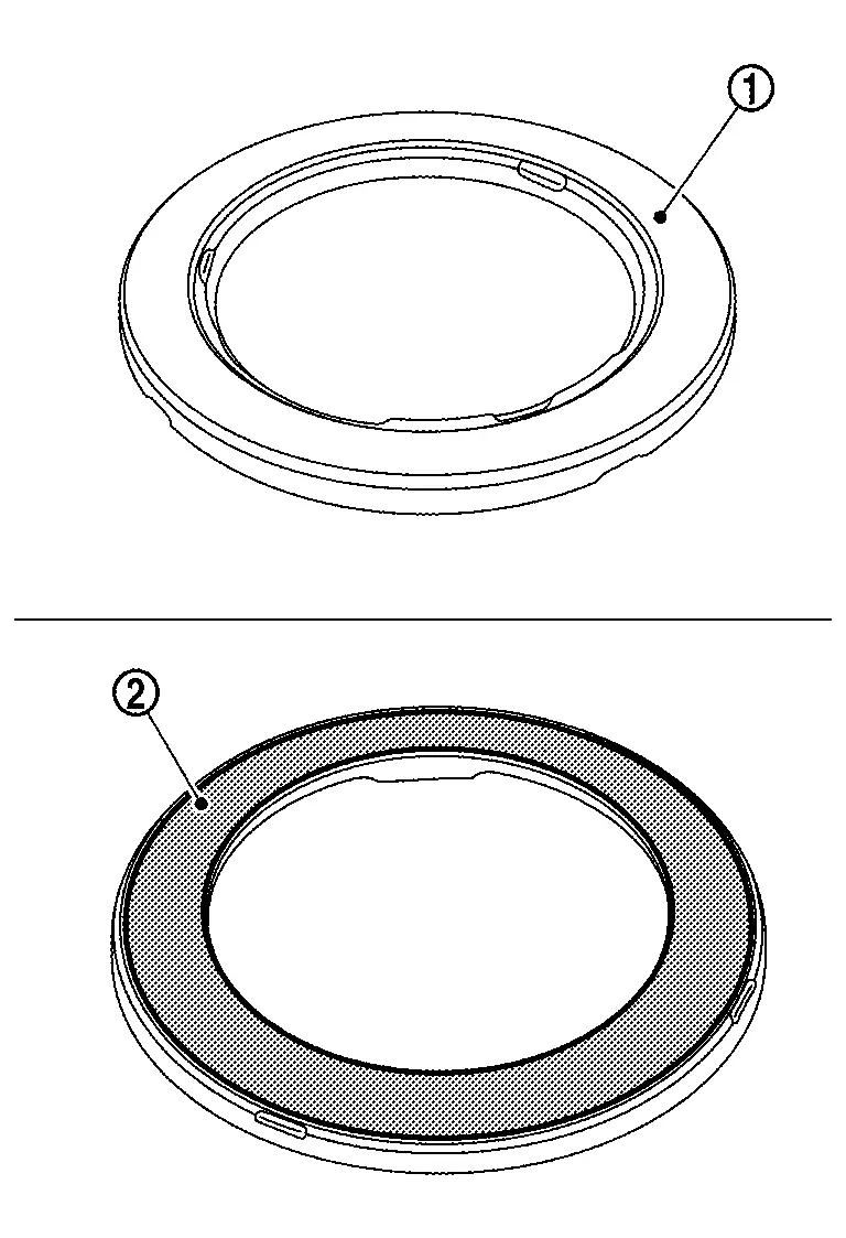
Install electric oil pump gasket .
CAUTION:
-
Apply petroleum jelly to oil pump gasket.
-
Never reuse the oil pump gasket.
Install electric oil pump bracket to electric oil pump.
CAUTION:
Never reuse electric oil pump bracket when replacing electric oil pump with a new one.
Install electric oil pump and terminal assembly A to transaxle case. Tighten mounting bolts of electric oil pump to the specified torque. Refer to Exploded View.
Tighten mounting bolts of electric oil pump bracket to the specified torque in numerical order and shown in the figure. Refer to Exploded View.
Install harness connector to terminal assembly A .
CAUTION:
When installing, never include any moisture, contamination into harness connector.
Install herness connector of terminal assembly B to the electric oil pump.
CAUTION:
-
Never reuse terminal assembly B.
-
When installing, never include any moisture, contamination into harness connector.
Insert the terminal assembly A to the hole of transaxle case, and then push it to seat completely.
CAUTION:
Apply petroleum jelly to O-ring of terminal assembly A.
NOTE:
Completely push CVT unit connector until click noise is made.
Tighten each mounting bolt and for terminal assembly A and terminal assembly B with specified torque. Refer to Exploded View.
Install gasket to TCM.
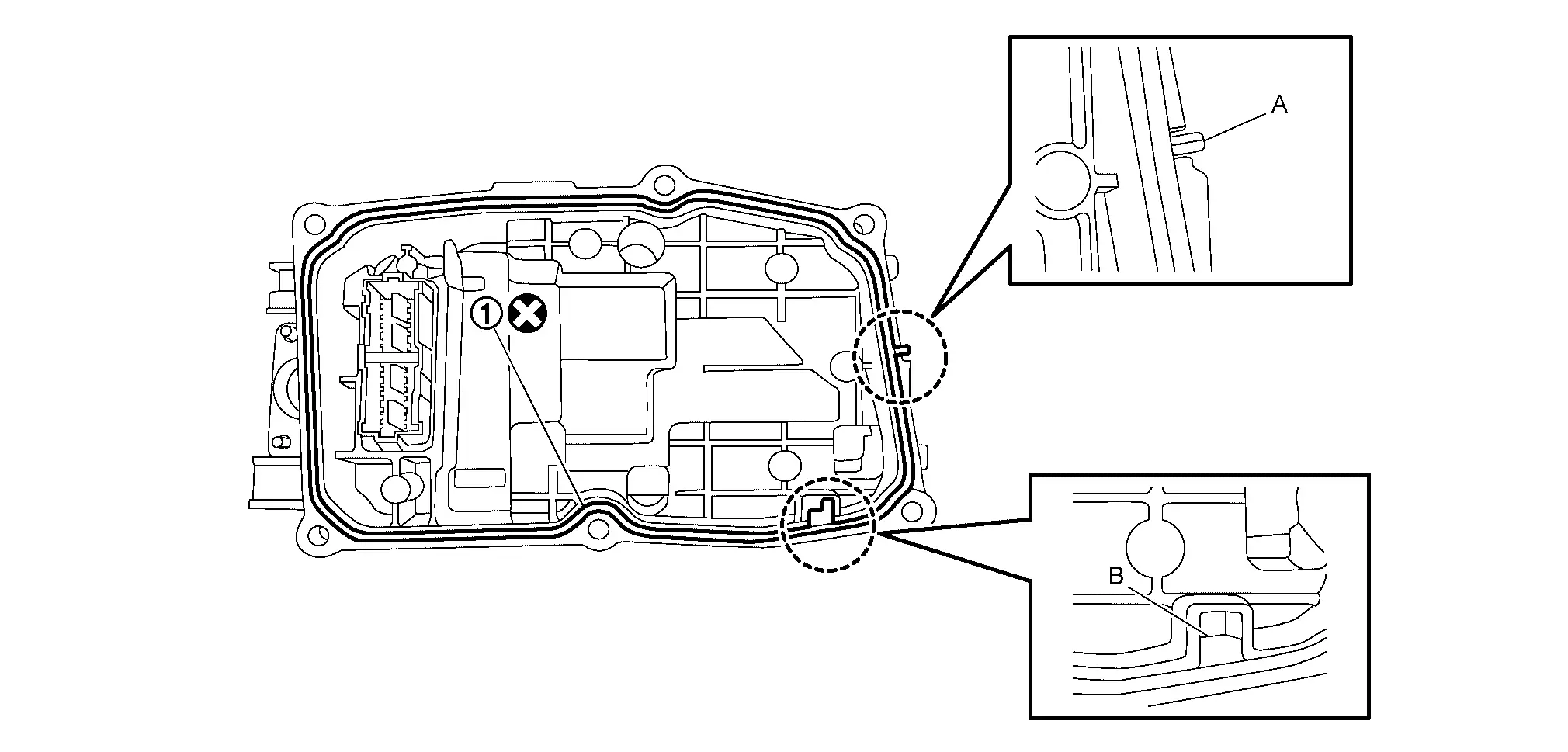
CAUTION:
Never reuse the gasket
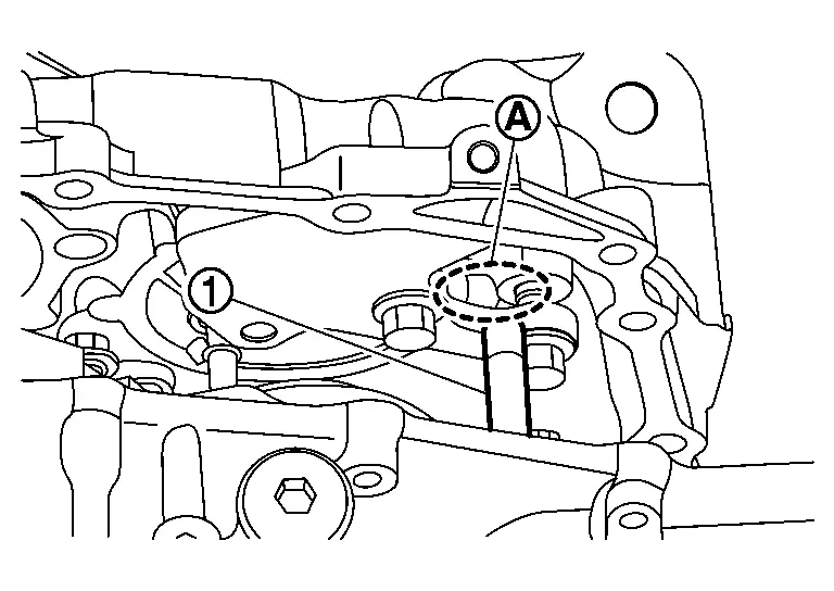
NOTE:
Two tabs (A and B) on TCM gasket need to be set to notches on TCM case.
Install connectors of terminal assembly B to TCM.
NOTE:
Terminal assembly B connector claws are located on the upper and lower sides of the connector while connected to the TCM.
Tighten TCM mounting bolts ( 6 pieces) to the specified torque. Refer to Exploded View.
|
: TCM |
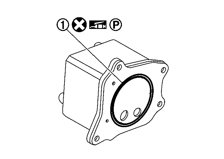
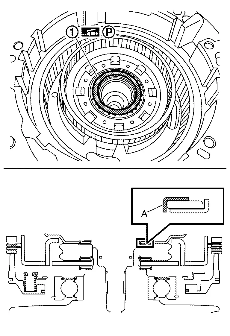
Install lip seal to transaxle assembly .
CAUTION:
-
Apply petroleum jelly to lip seal.
-
Never reuse the lip seal.
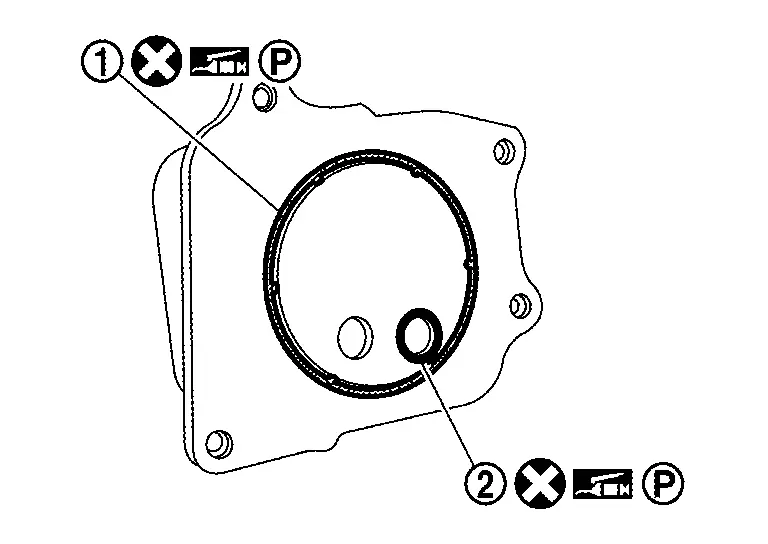
Remove O-rings and from tubes and .
CAUTION:
-
Apply petroleum jelly to O-ring.
-
Never reuse the O-ring.
Install tubes and to transaxle assembly .
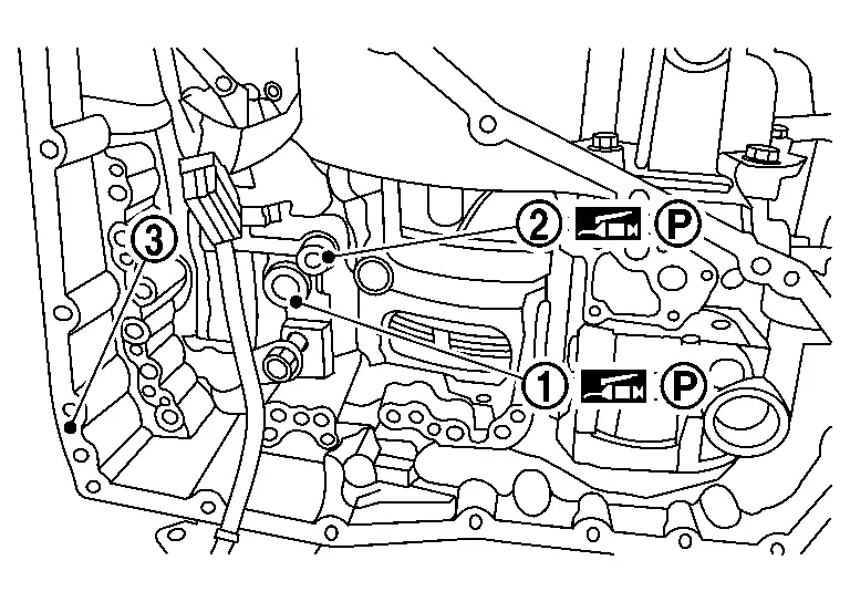
CAUTION:
-
While installing, never drop tube.
-
Never reuse dropped and damaged tube.
-
Apply petroleum jelly to the tubes to keep them in place on the transaxle case.
NOTE:
Fully push tubes to reach to the end.
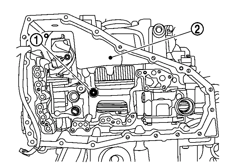
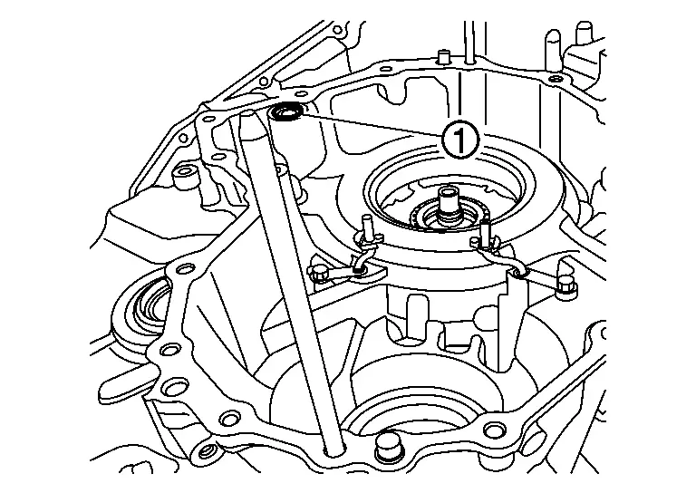
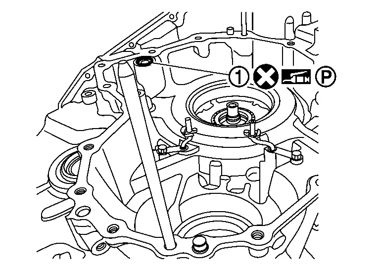
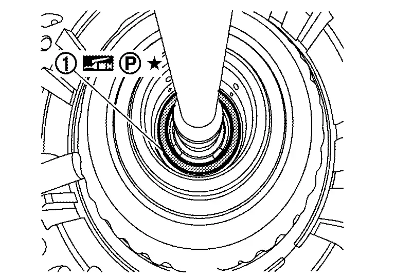
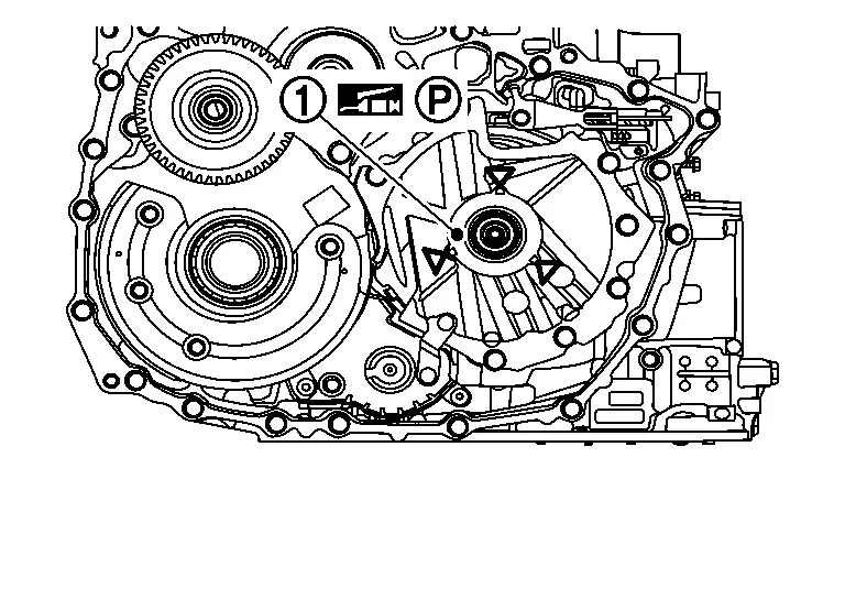
Set position of manual shaft and manual valve to "N", before installing control valve.
NOTE:
-
While inserting valve body alignment tool (SST:NI-53064)
etc. through both holes of control valve body and manual valve, set manual valve position to "N" . After that pull out a rod. -
Align matching marks
.
-
Install the control valve
with mounting bolts ( 10 pieces) which exists on the outline of control valve according to the sequence of , and .
: Nissan Ariya Vehicle front Bolt Bolt length mm (in) Number of bolt 54 (2.13) 1 44 (1.73) 3 40 (1.57) 6 NOTE:
Install mounting bolts by hand tightening.
CAUTION:
-
There are 3 types of bolts for control valve installation. Install the bolts to appropriate position.
-
When installing the control valve, prevent it from tilting with respect to the case, and ensure positioning with the dowel pin.
-
-
Tighten ten control valve mounting bolts to the specified torque. Refer to Exploded View.
-
After tightening the control valve mounting bolts, check that the manual plate
engages with the manual valve and that the manual shaft rotates normally.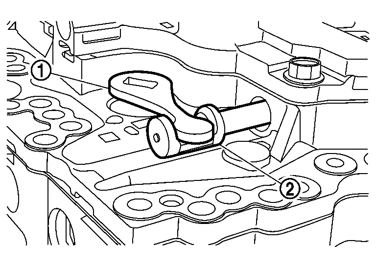
Install harness connectors and harness clip .
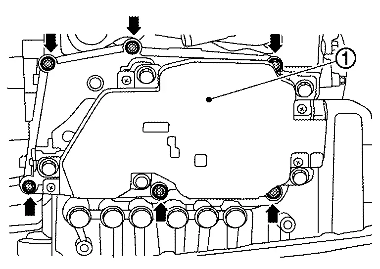
Install oil strainer assembly and then tighten oil strainer assembly mounting bolts to the specified torque. Refer to Exploded View.
CAUTION:
-
Never reuse oil strainer assembly.
-
Apply CVT fluid to O-ring
and of new oil strainer assembly.
Install oil pan magnets ( 9 pieces).
CAUTION:
-
Clean the magnets.
-
Clean the oil pan.
-
Align the magnets with the recesses in the oil pan to install them as shown in the figure.
Install oil pan gasket .
CAUTION:
Never reuse the oil pan gasket.
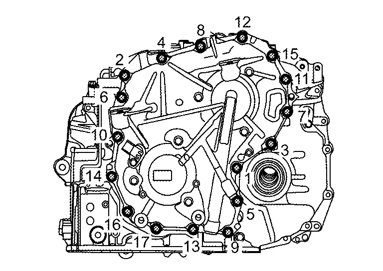
Install oil pan and then tighten oil pan mounting bolts to the specified torque in numerical order shown in the figure. Refer to Exploded View.
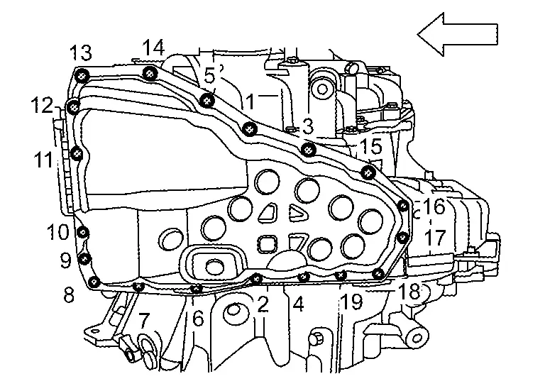
CAUTION:
Apply CVT fluid to the bolts when installing.
| : Nissan Ariya Vehicle front |
Install drain plug gasket and drain plug to the specified torque. Refer to Exploded View.
CAUTION:
Never reuse the drain plug gasket.
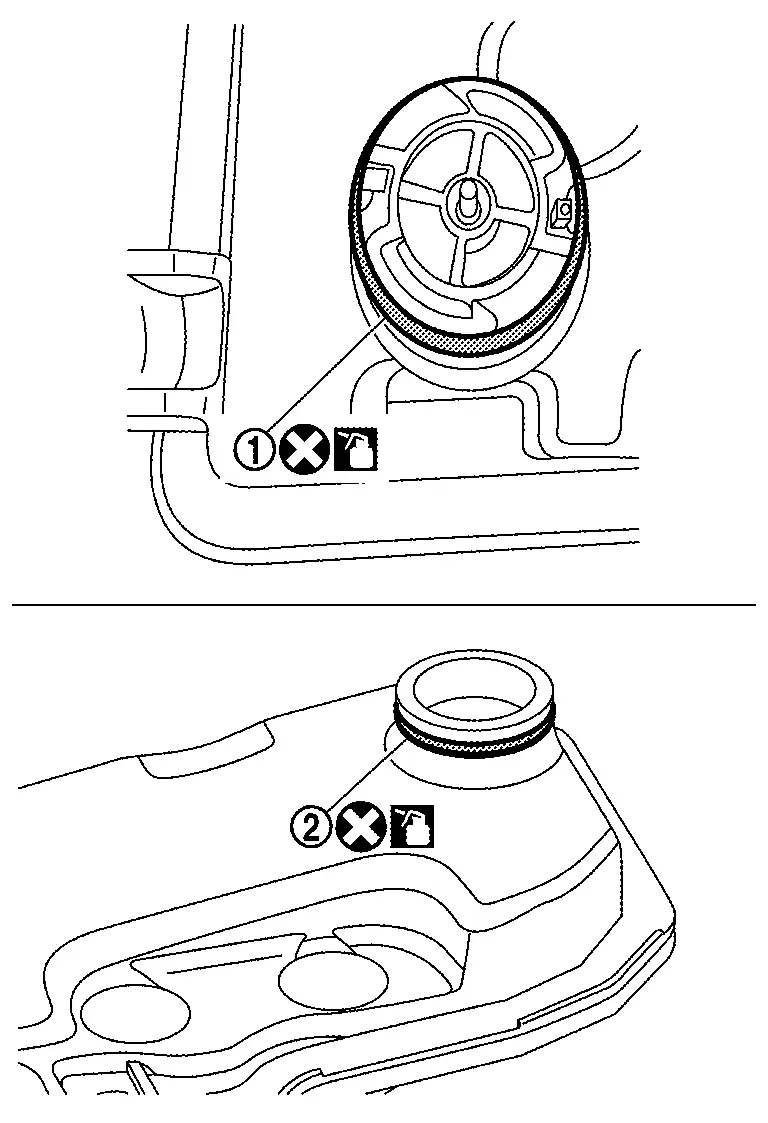
Install oil filter .
CAUTION:
-
Never reuse the oil filter.
-
Apply CVT fluid to the grommet seal.
Install O-ring to and from CVT oil warmer.
NOTE:
There are one O-ring and two O-rings depending on the specifications. When reusing oil warmer, check the number of O-rings and use the same number of O-rings as the removed number.
-
Type with one O-ring.
-
Type with two O-ring
Install oil warmer and then tighten oil warmer mounting bolts to the specified torque. Refer to Exploded View.
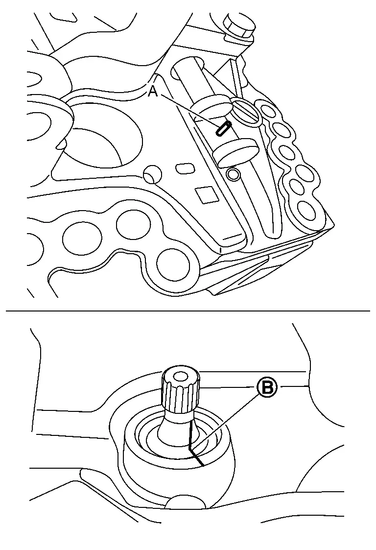
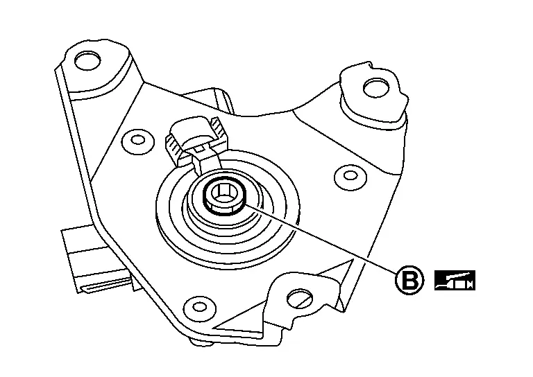
Install shift actuator and then tighten shift actuator mounting bolts to the specified torque. Refer to Exploded View.
NOTE:
-
Check that position of manual shaft side is 'N' before installing shift actuator.
-
Apply grease evenly to the shift actuator spline
before installing shift actuator.
Install O-ring to primary pulley speed sensor.
CAUTION:
-
Apply petroleum jelly to O-ring.
-
Never reuse the O-ring.
Install primary speed sensor , and then tighten primary speed sensor mounting bolt to the specified tightening torque. Refer to Exploded View.
Install O-ring to input speed sensor.
CAUTION:
-
Apply petroleum jelly to O-ring.
-
Never reuse the O-ring.
Install input speed sensor , and then tighten input speed sensor mounting bolt to the specified tightening torque. Refer to Exploded View.
Install new serial number sticker on shift actuator .
Install torque converter. Refer to Assembly.
Install the transaxle assembly to the Nissan Ariya vehicle. Refer to Removal and Installation.
Fill the transaxle assembly with CVT fluid. Refre to Refilling.
Perform "ADDITIONAL SERVICE WHEN REPLACING CONTROL VALVE". Refer to Description.
Trouble Shooting
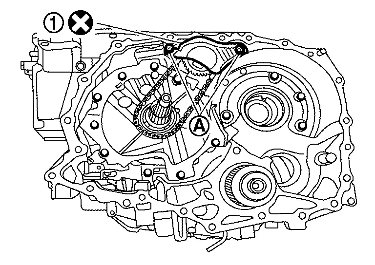
The Dummy Cover Will Not Sit Flush
NOTE:
-
If the dummy cover does not sit flush, the forward clutch assembly may not be fully seated. The forward clutch assembly is not fully seated if it is not below the surface that the dummy cover bolts to.
: Transaxle case : Forward clutch assembly : The clearance between the dummy cover and the forward clutch assembly -
Always handle the forward clutch assembly by the input shaft.
-
Remove the dummy cover
.
-
Pull up the forward clutch assembly
by the input shaft to remove the entire forward clutch assembly.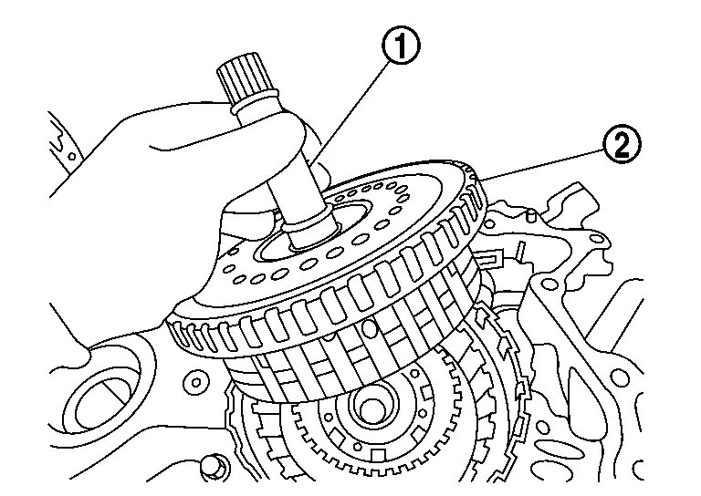
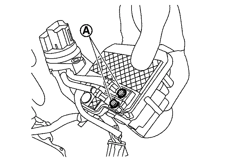
-
Using a suitable tool (A) gently align the layers
of the forward clutch assembly .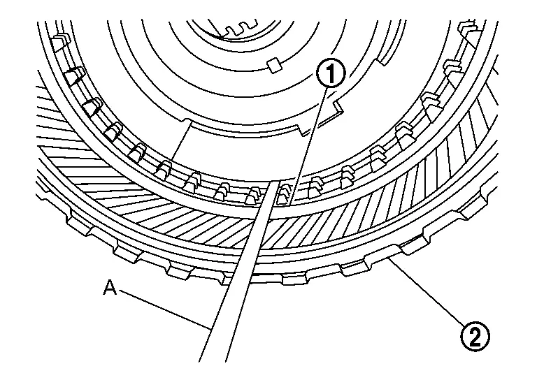
-
Re-insert the entire forward clutch assembly
while holding the input shaft .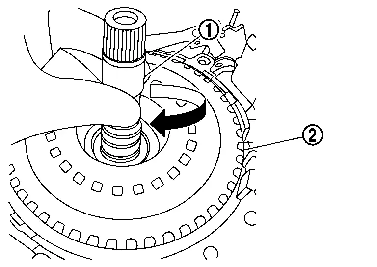 NOTE:
NOTE:
-
Gently jiggle the input shaft until the forward clutch assembly seats below case lip.
-
If the forward clutch assembly does not seat, rotate back and forth from the input shaft and jiggle.
-
If the clutch pack still does not seat, repeat from step 3.
-
Other materials:
P11a8 Vcr Target Angle
DTC Description
DTC DETECTION LOGIC DTC
CONSULT screen terms
(Trouble diagnosis content)
DTC detection condition
P11A8
00
VCR target angle
(Variable compression ratio target angle)
Diagnosis condition
Engine running at idle
Engine speed : 4,500 rpm or more
...
How to Erase Permanent Dtc
Description
OUTLINEWhen a DTC is stored in control moduleWhen
a DTC is stored in control module and MIL is ON, a permanent DTC is
erased with MIL shutoff if the same malfunction is not detected after
performing the driving pattern for MIL shutoff three times in a raw. *1:
When the same mal ...
Système 4x4 Intelligent
En cas de dysfonctionnement du système 4x4 Intelligent du Nissan Rogue alors que le moteur est en marche, différents messages d'avertissement peuvent s'afficher sur l'écran d'informations du véhicule afin d'informer le conducteur de l'état du système de transmission intégrale.
Si l'a ...