Nissan Rogue (T33) 2021-Present Service Manual: System Description :: System
System Description
-
An Electrically-driven Intelligent Brake Unit is a booster system that generates assist force by using an internal motor to operate a piston inside the master cylinder part.
-
Control module is integrated with Electrically-driven Intelligent Brake Unit.
-
The amount of brake pedal operation is detected by the stroke sensor, and sent to the control module of the Electrically-driven Intelligent Brake Unit.
-
Based on the commands from the control module of the Electrically-driven Intelligent Brake Unit, the motor inside the Electrically-driven Intelligent Brake Unit operates and presses the piston of master cylinder part.
-
Pressing the master cylinder piston, and brake fluid is sent to the ABS actuator and electric unit (control unit).
-
CONSULT can be used to diagnose the system diagnosis.
-
When there is a malfunction in the power system of the Electrically-driven Intelligent Brake Unit (no voltage is generated), voltage is temporarily supplied to the Electrically-driven Intelligent Brake Unit from the brake power supply backup unit. At the same time, the brake warning lamp and brake system warning lamp turn ON, and the warning buzzer sounds.
-
When a malfunction occurs in the Electrically-driven Intelligent Brake Unit, the VDC function performs control (boost operation). At the same time, the brake warning lamp and brake system warning lamp turn ON.
-
When a malfunction occurs in the PDM (Power Delivery Module) and 12V battery, the braking force is determined by the force pressing on the brake pedal (no boost operation). At the same time, the brake warning lamp and the brake system warning lamp turn ON.
-
When a malfunction occurs in the brake power supply backup unit, the brake system warning lamp turn ON.
-
When a malfunction occurs in the Electrically-driven Intelligent Brake Unit and in the VDC function, the braking force is determined by the force pressing on the brake pedal (no boost operation). At the same time, the brake warning lamp and brake system warning lamp turn ON.
-
When a malfunction occurs only Electrically-driven Intelligent Brake Unit, Electrically-driven Intelligent Brake Unit transmits to ABS actuator and electric unit (control unit) that Electrically-driven Intelligent Brake Unit is malfunction state.
-
A fail-safe function is available and is activated when a system malfunction occurs. Refer to Fail-safe.
SYSTEM DIAGRAM
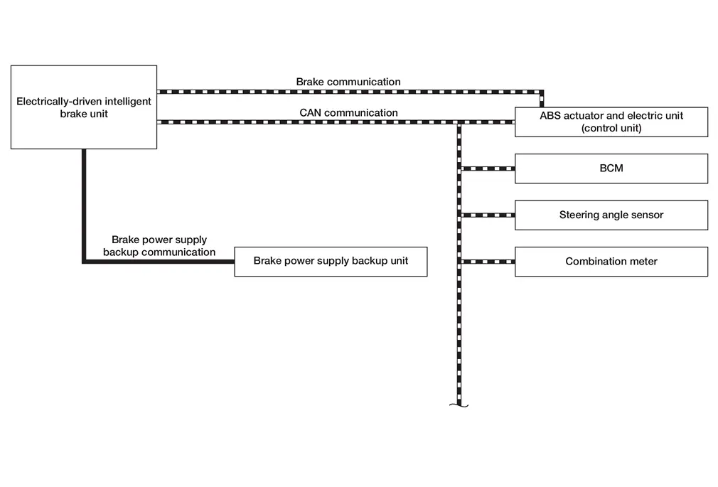
INPUT SIGNAL AND OUTPUT SIGNAL
Major signal transmission between each unit via communication lines is shown in the following table.
| Component | Function |
|---|---|
| Electrically-driven Intelligent Brake Unit | Refer to Component Description. |
| Brake power supply backup unit | Refer to Component Description. |
| Steering angle sensor |
Mainly transmits the following signal to Electrically-driven Intelligent Brake Unit via CAN communication.
|
| Combination meter |
Mainly receives the following signals from ABS actuator electric unit (control unit) via Electrically-driven Intelligent Brake Unit via CAN communication.
|
| ABS actuator and electric unit (control unit) |
Mainly transmits the following signals to Electrically-driven Intelligent Brake Unit via CAN communication.
Mainly receives the following signals from Electrically-driven Intelligent Brake Unit via CAN communication.
|
| BCM |
Mainly transmits the following signals to Electrically-driven Intelligent Brake Unit via CAN communication.
|
CONDITION FOR OPERATION OF THE WARNING LAMP AND THE WARNING BUZZER
Turns ON when Ignition switch turns ON and turns OFF when the system is normal, for bulb check.
| Condition (status) | Brake warning lamp (red) | Brake system warning lamp (yellow) | Warning buzzer |
|---|---|---|---|
| Ignition switch OFF | OFF | OFF | OFF |
| For several seconds after the Ignition switch is ON | ON | ON | OFF |
| Several seconds after Ignition switch ON (when the system is in normal operation) | OFF | OFF | OFF |
| When the power supply to the Electrically-driven Intelligent Brake Unit is changed from the 12V battery to the brake power supply backup unit | ON | ON | ON |
| Brake power supply backup unit is malfunctioning | OFF | ON | OFF |
| Electrically-driven Intelligent Brake Unit is malfunctioning | ON | ON | OFF |
| When brake fluid is less than the specified level (brake fluid level switch ON) | ON | OFF | OFF |
Fail-safe
-
When there is a malfunction in the power system of the Electrically-driven Intelligent Brake Unit (no voltage is generated), voltage is temporarily supplied to the Electrically-driven Intelligent Brake Unit from the brake power supply backup unit. At the same time, the brake warning lamp and brake system warning lamp turn ON and the buzzer sounds.
-
When a malfunction occurs in the Electrically-driven Intelligent Brake Unit, the VDC function performs control (boost operation).
-
When a malfunction occurs in the PDM (Power Delivery Module) and 12V battery, the braking force is determined by the force pressing on the brake pedal (no boost operation). At the same time, brake warning lamp and the brake system warning lamp turn ON.
-
When a malfunction occurs in the brake power supply backup unit, the brake system warning lamp turn ON.
-
When a malfunction occurs in the Electrically-driven Intelligent Brake Unit and in the VDC function, the braking force is determined by the force pressing on the brake pedal (no boost operation). At the same time, the brake warning lamp and brake system warning lamp turn ON.
| DTC | Fail-safe condition |
|---|---|
| B14E0-02 | Normal control |
| B14E0-09 | |
| B14E0-11 | |
| B14E0-12 | |
| B14E0-13 | |
| B14E0-1C | |
| B14E0-38 | |
| B14E0-4A | |
| B14E0-64 | |
| B14E1-02 | |
| B14E1-09 | |
| B14E1-11 | |
| B14E1-12 | |
| B14E1-13 | |
| B14E1-1C | |
| B14E1-38 | |
| B14E1-4A | |
| B14E1-64 | |
| B14E2-02 | |
| B14E2-09 | |
| B14E2-11 | |
| B14E2-12 | |
| B14E2-13 | |
| B14E2-1C | |
| B14E2-38 | |
| B14E2-4A | |
| B14E2-64 | |
| B14E3-02 | |
| B14E3-09 | |
| B14E3-11 | |
| B14E3-12 | |
| B14E3-13 | |
| B14E3-1C | |
| B14E3-38 | |
| B14E3-4A | |
| B14E3-64 | |
| B14E4-64 | |
| B14E5-64 | Normal control |
| B14E5-92 | |
| B14E6-85 | |
| B14E6-92 | |
| C18D0-01 |
The following functions are suspended.
|
| C18D1-09 | |
| C18D2-12 | |
| C18D3-14 | |
| C18D4-14 | |
| C18D5-09 | |
| C18D6-09 | |
| C18D7-09 | |
| C18D8-09 | |
| C18D9-09 | |
| C18DA-09 | |
| C18DB-09 | |
| C18DC-09 | |
| C18DD-09 | |
| C18DE-82 | |
| C18DE-83 | |
| C18DE-87 | |
| C18E1-04 | Normal control |
| C18E1-07 |
The following functions are suspended.
|
| C18E1-18 | |
| C18E1-19 | |
| C18E1-49 | |
| C18E1-4B | |
| C18E3-86 | |
| C18E4-88 | |
| C18E5-88 | |
| C18E6-49 | |
| C18E7-13 | Normal control |
| C18E7-16 | Normal control |
| C18E7-17 | |
| C18E7-1C | |
| C18E9-01 | |
| C18E9-04 | |
| C18E9-44 | |
| C18E9-45 | |
| C18E9-46 | |
| C18E9-47 | |
| C18E9-48 | |
| C18E9-49 | |
| C18E9-96 | |
| C18EA-01 | |
| C18EB-01 | |
| C18EC-01 |
The following functions are suspended.
|
| C18EC-04 | |
| C18EC-11 | |
| C18EC-12 | |
| C18EC-13 | |
| C18EC-14 | |
| C18EC-15 | |
| C18EC-1F | |
| C18ED-04 | |
| C18EE-01 | |
| C18EE-04 | |
| C18EE-64 | |
| C18EE-87 | |
| C18EE-96 | |
| C18EF-16 | |
| C18EF-17 | |
| C18EF-96 | |
| C18F1-08 | |
| C18F3-04 | |
| C18F3-4B | |
| C18F4-86 | Normal control |
| C18F5-08 | |
| C18F6-08 | |
| C18F7-08 | Normal control |
| C18F7-86 | |
| C18F8-08 | Normal control |
| C18F8-86 | |
| C18F9-02 | |
| C18FA-44 | Normal control |
| C18FA-46 | Normal control |
| C18FC-18 | Normal control |
| C18FC-19 | |
| C18FD-18 | |
| C18FD-19 | |
| C18FE-29 | |
| U1FA1-86 | Normal control |
| U2140-87 | |
| U2143-87 | |
| U2148-87 | Normal control |
| U214F-87 | Normal control |
| U2240-87 | |
| U2243-87 | |
| U2248-87 | Normal control |
| U224F-87 | Normal control |
| U2252-87 | |
| U225B-87 |
Warning / Indicator / Chime List
| Name | Design | Layout / Function |
|---|---|---|
| Brake warning lamp |  |
For layout: Refer to Design. |
| For function: Refer to Brake Warning Lamp. | ||
| Brake system warning lamp |  |
For layout: Refer to Design. |
| For function: Refer to Brake Warning Lamp. |
| Name | Design | Layout / Function |
|---|---|---|
| Brake warning lamp | |
For layout: Refer to Design. |
| For function: Refer to Brake Warning Lamp. | ||
| Brake system warning lamp |  |
For layout: Refer to Design. |
| For function: Refer to Brake Warning Lamp. |
Other materials:
Réduction active du bruit / Amélioration active du son
REMARQUE :
Pour garantir le bon fonctionnement des systèmes de réduction active du bruit et d’amélioration active du son du Nissan Rogue :
Ne couvrez pas les haut-parleurs ni le woofer.
Ne couvrez pas les microphones intégrés.
Ne modifiez pas les haut-parleurs, le woofer, l’a ...
Symptom Diagnosis. Door Does Not Lock/unlock with Door Request Switch and Intelligent Key
Description
All doors do not lock/unlock using door request switch.SYMPTOM TABLE (BOTH INTELLIGENT KEYS HAVE THE SAME SYMPTOMS) Door lock operation (remote keyless entry)
Door lock operation (request switch of front/rear/back door) or
trunk/back door open operation (opener switch of trunk/back ...
Ivc Branch Line Circuit
Diagnosis Procedure
CHECK CONNECTOR
Turn the ignition switch OFF.
Disconnect the battery cable from the negative terminal.
Check the following terminals and connectors for damage, bend and loose connection (unit side and connector side).
TCU
8CH CAN gateway
Is the ...