Nissan Rogue (T33) 2021-Present Service Manual: System Description :: Component Parts
Component Parts Location
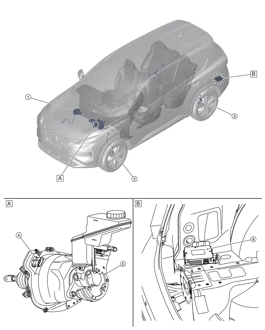
| A. | Engine Room (LH Side) | B. | Rear trunk with finisher removed | ||
| No. | Component | Function |
|---|---|---|
| 1. | ABS (Anti-lock Braking System) Actuator and Electric Unit (Control Unit) | Refer to Component Parts Location for detailed component location. |
| 2. | Front wheel sensor LH (RH Similar) | Refer to Wheel Sensor and Sensor Rotor for detailed component location. |
| 3. | Rear wheel sensor LH (RH Similar) | Refer to Wheel Sensor and Sensor Rotor for detailed component location. |
| 4. | Stroke sensor | Refer to Component Description. |
| 5. | Electrically-driven Intelligent Brake Unit | Refer to Component Description. |
| 6. | Brake power backup unit | Refer to Component Description. |
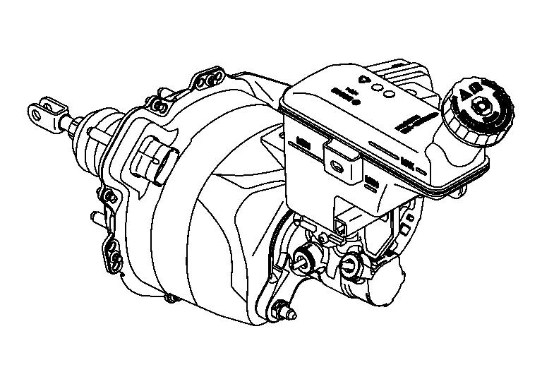
Electrically-Driven Intelligent Brake Unit
Component Description
FUNCTIONS WITHIN THE SYSTEM
Integrates the control module, master cylinder, brake booster, and stroke sensor and it controls the fluid pressure that is sent to the ABS actuator and electric unit (control unit).
INDIVIDUAL FUNCTIONS WITHIN THE SYSTEM
Integrates the control module, master cylinder, brake booster, and stroke sensor.
CONTROL MODULE
-
Controls the fluid pressure that is applied to the brake calipers, based on the signals from each sensor and unit.
-
When a malfunction is detected, the system enters fail-safe mode.
MASTER CYLINDER
-
Generates brake fluid pressure according to the amount of piston movement.
-
The fluid pressure generated by the master cylinder is sent to the ABS actuator and electric unit (control unit).
BRAKE BOOSTER
-
Contains a motor and generates boost force according to the amount that the brake pedal is depressed.
-
Uses the boost force to generate fluid pressure in the master cylinder.
INDIVIDUAL OPERATION
-
Brake control: Refer to System Description.
PARTS LOCATION
Refer to DTC Index.
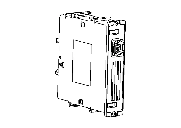
Brake Power Backup Unit
Component Description
FUNCTIONS WITHIN THE SYSTEM
When there is a malfunction in the power system of the Electrically-driven Intelligent Brake Unit (no voltage is generated), this unit temporarily supplies voltage to the Electrically-driven Intelligent Brake Unit.
INDIVIDUAL FUNCTIONS WITHIN THE SYSTEM
In preparation for the malfunction in the power system of the Electrically-driven Intelligent Brake Unit (no voltage is generated), electric power is stored.
INDIVIDUAL OPERATION
Refer to System Description.
PARTS LOCATION
Refer to Component Parts Location.
Other materials:
P12a8 Cruise Control
DTC Description
DTC DETECTION LOGIC DTC
CONSULT screen terms
(Trouble diagnosis content) DTC detecting condition
P12A8
00
Cruise control communication
(Cruise control)
Diagnosis condition
Ignition switch ON
Signal
CAN communication signal
Threshold
Abnormal driv ...
Liquide de frein
Pour des informations dÃĐtaillÃĐes concernant le type, la capacitÃĐ et les spÃĐcifications du liquide de frein, reportez-vous à la section ÂŦ Contenances et liquides/lubrifiants recommandÃĐs Âŧ de ce manuel du Nissan Rogue.
AVERTISSEMENT
Utilisez uniquement du liquide de frein neuf provenant ...
C10b7-16 Parking Brake Power Supply
DTC Description
DTC DETECTION LOGIC DTC No.
CONSULT screen terms
(Trouble diagnosis content) DTC detection condition
C10B7
16
Parking brake power supply
(Parking brake power supply)
Diagnosis condition
When ignition switch ON.
Signal (terminal)
Ignition power supply
...