Nissan Rogue (T33) 2021-Present Service Manual: System Description :: Component Parts. Wiper and Washer System
Wiper and Washer System
Component Parts Location
Component Parts Location

| A. | View with washer tank removed from Nissan Ariya vehicle (for USA) | B. | View with washer tank removed from vehicle | C. | Behind LH side of front fascia assembly (view with front fascia assembly) removed |
| No. | Component | Function |
|---|---|---|
| 1. | Rain and light sensor (if equipped) | Refer to Rain and Light Sensor. |
| 2. | ABS (Anti-lock Braking System) actuator and electric unit (control unit) |
Transmits the Nissan Ariya vehicle speed signal to the BCM via CAN communication. Refer to ABS Actuator and Electric Unit (Control Unit) for detailed component location. |
| 3. | Electric shift control module |
Transmits the reverse switch signal to the BCM via CAN communication. Refer to Electric Shift Control Module for detailed component location. |
| 4. | IPDM E/R (Intelligent Power Distribution Module Engine Room) |
|
| 5. | Front wiper motor | Refer to Front Wiper Motor. |
| 6. | BCM (Body Control Module) |
|
| 7. | Combination switch (Wiper and washer switch) | Refer to Wiper and Washer Switch. |
| 8. | Rear wiper motor | Refer to Rear Wiper Motor. |
| 9. | Front and rear washer pump | Refer to Front And Rear Washer Pump. |
| 10. | Washer fluid level switch * | Refer to Washer Fluid Level Switch. |
| 11. | Front washer pump relay | Supplies power to the washer pump for front and rear washer pump operation. |
| 12. | Rear washer pump relay |
*: Canadian market
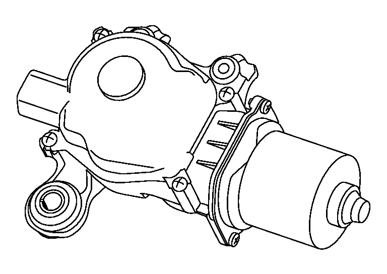
Front Wiper Motor
COMPONENT FUNCTION WITHIN SYSTEM
-
Controls front wiper operation with IPDM E/R control.
-
Transmits the front wiper stop position signal to the IPDM E/R.
INDIVIDUAL COMPONENT FUNCTION
Front wiper motor operates the front wiper.
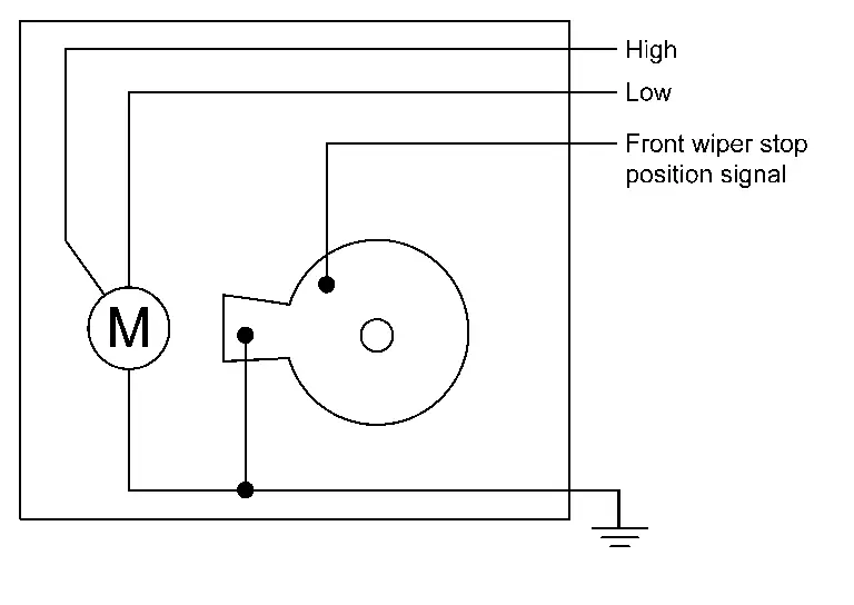
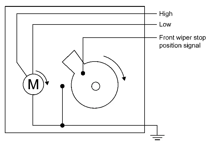
COMPONENT OPERATION
-
When power is supplied to the HI terminal of the front wiper motor, front wiper HI operates.
-
When power is supplied to the LO terminal of the front wiper motor, front wiper LO operates.
-
When there is a front wiper motor at the stop position, two points of contact in the front wiper motor are connected, and the front wiper stop position signal circuit is grounded.
-
When the front wiper motor operates, two points of contact in the front wiper motor are not connected, and the front wiper stop position signal circuit is not grounded.
-
IPDM E/R detects the front wiper stop position signal from the front wiper motor to find out the front wiper motor position (stop position/except stop position).
COMPONENT PARTS LOCATION
Front wiper motor is installed under the cowl top cover.
Refer to Component Parts Location.
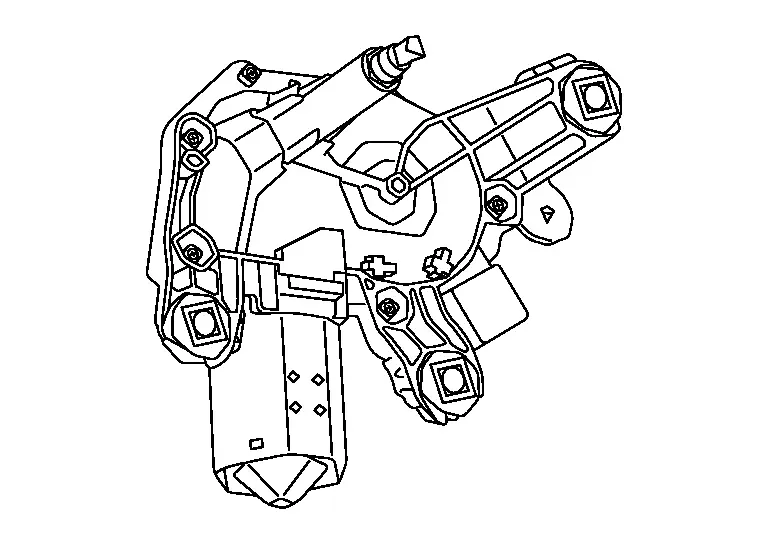
Rear Wiper Motor
COMPONENT FUNCTION WITHIN SYSTEM
-
Controls rear wiper operation with BCM control.
-
Transmits the rear wiper stop position signal to the BCM.
INDIVIDUAL COMPONENT FUNCTION
Rear wiper motor operates rear wiper.
COMPONENT OPERATION
-
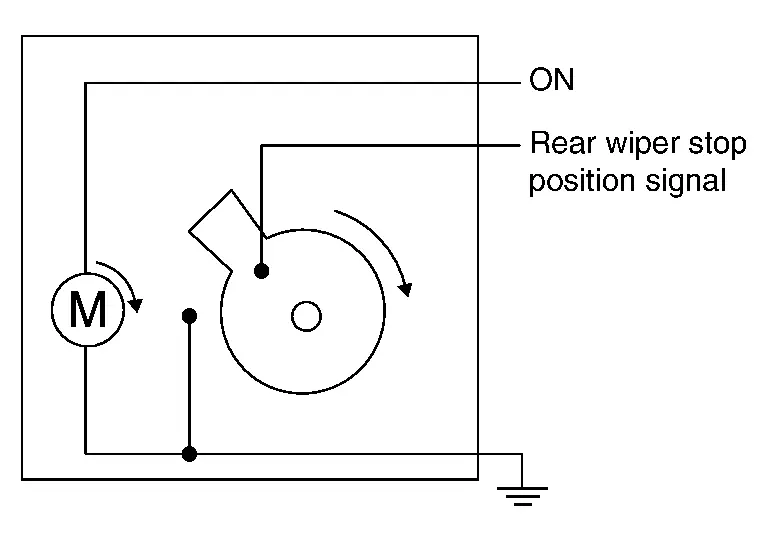
When power is supplied to the ON terminal of the rear wiper motor, the rear wiper motor operates the rear wiper.
-
When the rear wiper motor is at the stop position, two points of contact in the rear wiper motor are connected, and the rear wiper stop position signal circuit is grounded.
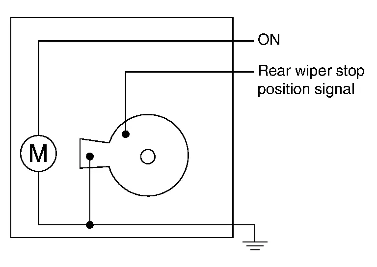
-
When the rear wiper motor operates, two points of contact in the rear wiper motor are not connected, and the rear wiper stop position signal circuit is not grounded.
-
BCM detects the rear wiper stop position signal from the rear wiper motor to find out the rear wiper motor position (stop position/except stop position).
COMPONENT PARTS LOCATION
Rear wiper motor is installed on the back door.
Refer to Component Parts Location.
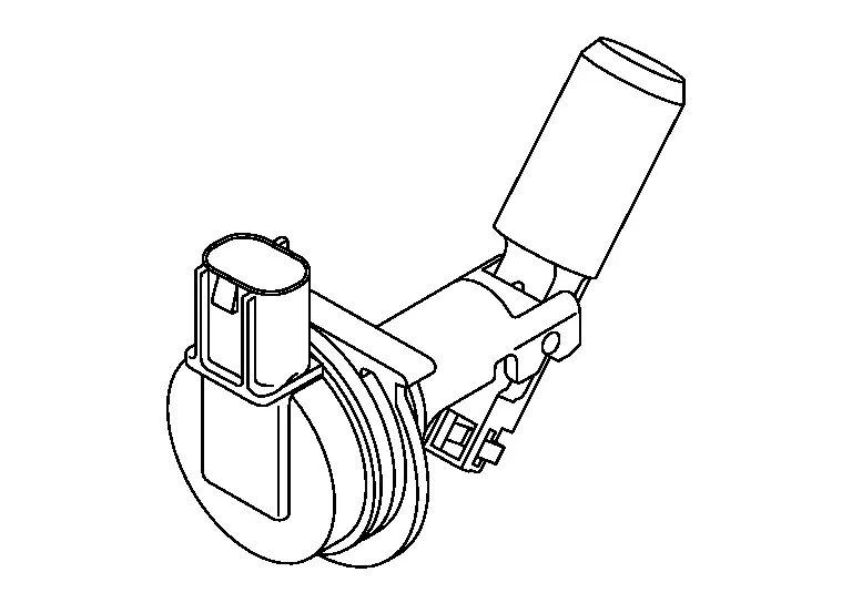
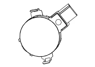
Front And Rear Washer Pump
COMPONENT FUNCTION WITHIN SYSTEM
Front and rear washer pump operates the front or rear washer.
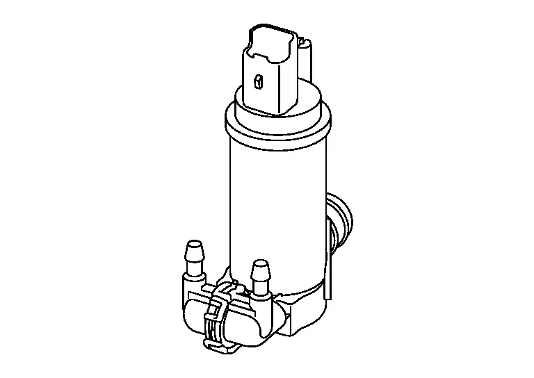
INDIVIDUAL COMPONENT FUNCTION
Front and rear washer pump sprays washer fluid depending on the state of the washer switch.
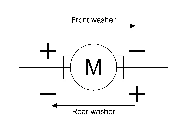
COMPONENT OPERATION
Front and rear washer pump changes voltage polarity to change the rotatory direction of the front and rear washer pump to operate the front washer or rear washer.
COMPONENT PARTS LOCATION
Front and rear washer pump is installed on the washer tank.
Refer to Component Parts Location.
Washer Fluid Level Switch
 NOTE:
NOTE:
Washer fluid level switch is only applied in Canada.
COMPONENT FUNCTION WITHIN SYSTEM
Detects that washer fluid level is low and transmits the washer fluid level switch signal to combination meter.
INDIVIDUAL COMPONENT FUNCTION
Detects that washer fluid level is low.
COMPONENT OPERATION
When washer fluid level is low, the float goes down and washer fluid level switch turns ON.
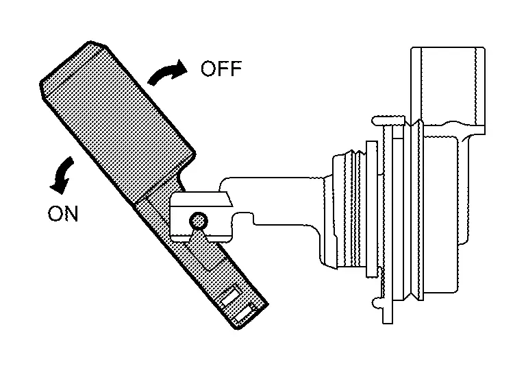
COMPONENT PARTS LOCATION
Washer fluid level switch is installed to the washer tank.
Refer to Component Parts Location.
Rain and Light Sensor
-
The rain and light sensor is installed on the windshield.
-
Detects water droplets on the windshield with infrared rays, and transmits the rain and light sensor signal to BCM via LIN communication.
Other materials:
Symptom Diagnosis. Squeak and Rattle Trouble Diagnoses
Work Flow
CUSTOMER INTERVIEWInterview
the customer if possible, to determine the conditions that exist when
the noise occurs. Use the Diagnostic Worksheet during the interview to
document the facts and conditions when the noise occurs and any customer
comments. Refer to Diagnostic Worksheet ...
Informations de base
SÃĐlecteur mode de conduite : ModÃĻles 4x2
SÃĐlecteur mode de conduite : ModÃĻles avec transmission
intÃĐgrale
Ãcran d'informations du vÃĐhicule : ModÃĻles 4x2
Ãcran d'informations du vÃĐhicule : ModÃĻles avec
transmission intÃĐgrale
Le Nissan Rogue propose plusieurs ...
Diagnosis System (bcm)
Common Item
CONSULT Function (BCM - COMMON ITEM)
BCM
Refer to CONSULT Function (BCM - COMMON ITEM).
Flasher
CONSULT Function (BCM - FLASHER)
BCM
Refer to CONSULT Function (BCM - FLASHER).
...