Nissan Rogue (T33) 2021-Present Service Manual: System Description :: System
Front Wiper and Washer System
System Description (Without Rain and Light Sensor Front Wipers)
SYSTEM DIAGRAM
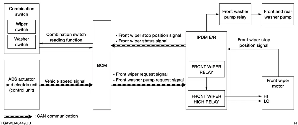
| Component | Function | |
|---|---|---|
| Front wiper motor | Refer to Front Wiper Motor. | |
| IPDM E/R | Controls integrated relays according to the request from the BCM via CAN communication. | |
| BCM |
|
|
| Combination switch (wiper & washer switch) | Combination switch: Transmits the status of the combination switch (wiper and washer) to BCM. | |
| ABS actuator and electric unit (control unit) | Transmits Nissan Ariya vehicle speed signal to the BCM via CAN communication. | |
| Front and rear washer pump | Refer to Front And Rear Washer Pump. | |
| Front washer pump relay | Controls front and rear washer pump according to the request from IPDM E/R. | |
OUTLINE
The front wiper is controlled by each function of BCM and IPDM E/R.
Control by BCM
-
Combination switch reading function
-
Front wiper control function
Control by IPDM E/R
-
Front wiper control function
-
Relay control function
Combination meter indicates low washer fluid warning judged with the signal from the washer fluid level switch. For details of low washer fluid warning, Refer to Washer Fluid.
| Signal name | Input | Output | Description |
|---|---|---|---|
| Combination switch signal | Combination switch (wiper and washer switch) | BCM | Inputs the combination switch signal to the BCM. |
| Nissan Ariya Vehicle speed signal | ABS actuator and electric unit (control unit) | BCM (CAN) | Transmits the Nissan Ariya vehicle speed signal via CAN communication. |
| Front wiper request signal | BCM | IPDM E/R (CAN) | Transmits the front wiper request signal via CAN communication. |
| Front washer pump request signal | BCM | IPDM E/R (CAN) | Transmits the front washer pump request signal via CAN communication. |
| Front wiper stop position signal | Front wiper motor | BCM (CAN) | Inputs the front wiper stop position signal and transmits via CAN communication. |
| Front wiper status signal | IPDM E/R | BCM (CAN) | Transmits the front wiper status signal via CAN communication. |
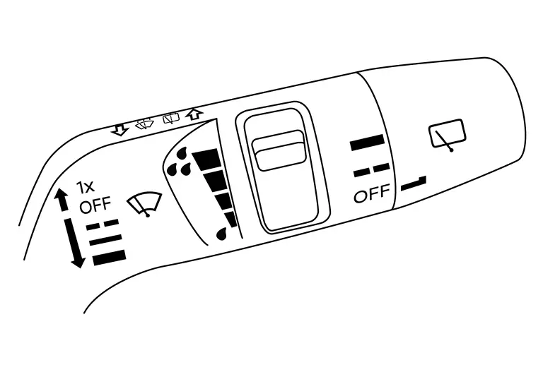
Wiper and Washer Switch
-
Wiper and washer switch is integrated with the combination switch.
- Wiper switch without rain sensing front wipers:
FRONT WIPER BASIC OPERATION
-
BCM detects the combination switch condition by the combination switch reading function.
-
BCM transmits the front wiper request signal to IPDM E/R via CAN communication depending on each operating condition of the front wiper.
-
IPDM E/R turns ON/OFF the integrated front wiper relay and the front wiper HIGH relay according to the front wiper request signal. IPDM E/R provides the power supply to operate the front wiper HI/LO operation.
FRONT WIPER LO OPERATION
-
BCM transmits the front wiper request signal (LOW) to IPDM E/R via CAN communication according to the front wiper LO operating condition.
Front wiper LO operating condition
-
Ignition switch ON
-
Front wiper switch LO or front wiper switch MIST (while pressing)
-
-
IPDM E/R turns ON the integrated front wiper relay according to the front wiper request signal (LOW).
FRONT WIPER HI OPERATION
-
BCM transmits the front wiper request signal (HIGH) to IPDM E/R via CAN communication according to the front wiper HI operating condition.
Front wiper HI operating condition
-
Ignition switch ON
-
Front wiper switch HI
-
-
IPDM E/R turns ON the integrated front wiper relay and the front wiper HIGH relay according to the front wiper request signal (HIGH).
FRONT WIPER INT OPERATION
-
BCM transmits the front wiper request signal (LOW) to IPDM E/R via CAN communication depending on the front wiper INT operating condition and intermittent operation delay interval according to the wiper volume dial position.
Front wiper INT operating condition
-
Ignition switch ON
-
Front wiper switch INT
-
-
IPDM E/R turns ON the integrated front wiper relay so that the front wiper is operated only once according to the front wiper request signal (LOW) and front wiper request signal (RETURN).
-
BCM detects stop position/except stop position of the front wiper motor according to the front wiper stop position signal received from IPDM E/R via CAN communication.
-
BCM transmits the front wiper request signal (LOW) again after the intermittent operation delay interval.
 NOTE:
NOTE:
Front wiper INT operation setting can change linked with Nissan Ariya vehicle speed ON or OFF setting through the combination meter.
Front wiper intermittent operation with vehicle speed
-
BCM calculates the intermittent operation delay interval from the following
-
Nissan Ariya Vehicle speed signal
-
Wiper volume dial position
-
Intermittent operation delay Interval
Unit: Second
| Intermittent operation interval | Nissan Ariya Vehicle speed | ||||
| Accelerating |
0 ŌĆō 3.1 MPH (0 ŌĆō 5 km/h) |
3.1 ŌĆō 40.4 MPH (5 ŌĆō 65 km/h) |
40.4 MPH (65 km/h) or more |
||
| Decelerating |
0 ŌĆō 1.2 MPH (0 ŌĆō 2 km/h) |
1.2 ŌĆō 37.3 MPH (2 ŌĆō 60 km/h) |
37.3 MPH (60 km/h) or more |
||
|
Long Ōåæ Ōåō Short |
Wiper volume dial position | 1 | 21.0 | 7.5 | 4.5 |
| 2 | 11.2 | 4.0 | 2.4 | ||
| 3 | 5.6 | 2.0 | 1.2 | ||
| 4 | 2.8 | 1.0 | 0.6 | ||
| 5 | 1.4 | 0.5 | 0.3 | ||
Unit: Second
| Intermittent operation interval | |||
|
Long Ōåæ Ōåō Short |
Wiper volume dial position | 1 | 15.0 |
| 2 | 8.0 | ||
| 3 | 4.0 | ||
| 4 | 2.0 | ||
| 5 | 1.0 | ||
FRONT WIPER AUTO STOP OPERATION
-
BCM transmits the front wiper request signal (RETURN) to IPDM E/R via CAN communication when the front wiper switch is turned OFF.
-
IPDM E/R detects the front wiper stop position signal from the front wiper motor to find out the front wiper motor position (stop position/except stop position).
-
When IPDM E/R receives the front wiper request signal (RETURN) from BCM and the front wiper motor position is not in the stop position, IPDM E/R turns ON the front wiper relay until the front wiper motor returns to the stop position.
-
When the front wiper motor returns to the stop position, IPDM E/R transmits front wiper status signal to BCM via CAN communication.
-
When BCM receives front wiper status signal from IPDM E/R, BCM transmits the front wiper request signal (STOP) to IPDM E/R via CAN communication.
FRONT WIPER OPERATION LINKED WITH WASHER
-
BCM transmits the front wiper request signal (LOW) to IPDM E/R via CAN communication according to the washer linked operating condition of the front wiper.
-
BCM transmits the front wiper request signal (LOW) so that the front wiper operates approximately 2 times when the front washer switch OFF is detected.
Washer linked operating condition of front wiper
-
Ignition switch ON
-
Front washer switch ON
-
-
IPDM E/R turns ON the integrated front wiper relay according to the front wiper request signal (LOW).
-
BCM transmits the front washer pump request signal to IPDM E/R via CAN communication depending on operating condition.
-
IPDM E/R turns ON /OFF the front washer pump relay according to the front washer pump request signal.
-
IPDM E/R provides the power supply and ground to operate the front and rear washer pump.
WIPER LINKED AUTO LIGHTING FUNCTION
When lighting switch is in the AUTO position, front wiper operates, and then headlamps turn ON. Refer to System Description.
System Description (With Rain and Light Sensor Front Wipers)
SYSTEM DIAGRAM
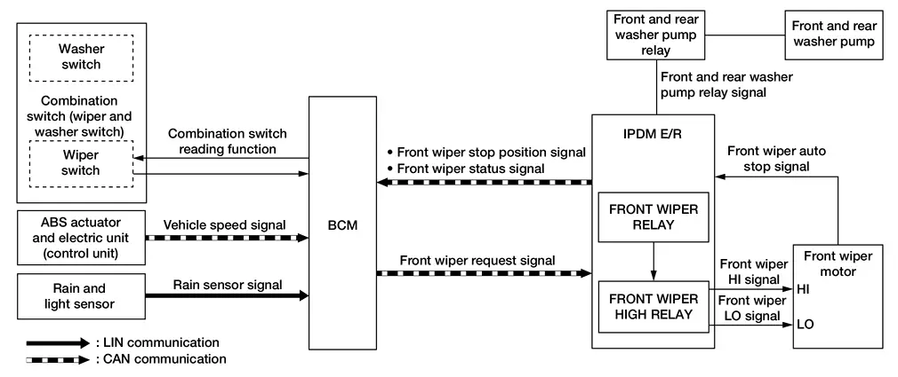
| Component | Function | |
|---|---|---|
| Front wiper motor | Refer to Front Wiper Motor. | |
| IPDM E/R | Controls the rear washer pump relay according to the request from the BCM via CAN communication. | |
| BCM | Supplies power to the rear wiper motor. | |
| Combination switch (wiper & washer switch) | Transmits the status of the combination switch (wiper and washer) to the BCM. | |
| ABS actuator and electric unit (control unit) | Transmits Nissan Ariya vehicle speed signal to the BCM via CAN communication. | |
| Front and rear washer pump | Refer to Front And Rear Washer Pump. | |
| Rain and light sensor | Transmits the rain sensor signal to the BCM via LIN communication. | |
OUTLINE
The front wiper is controlled by each function of BCM and IPDM E/R.
Control by BCM:
-
Combination switch reading function
-
Front wiper control function
-
Rain sensing wiper function
Control by IPDM E/R:
-
Front wiper control function
-
Relay control function
Combination meter indicates low washer fluid warning judged with the signal from the washer fluid level switch. For details of low washer fluid warning, Refer to Washer Fluid.
| Signal name | Input | Output | Description |
|---|---|---|---|
| Combination switch signal | Combination switch (wiper and washer switch) | BCM | Inputs the combination switch signal to the BCM. |
| Nissan Ariya Vehicle speed signal | ABS actuator and electric unit (control unit) | BCM (CAN) | Transmits the Nissan Ariya vehicle speed signal via CAN communication. |
| Front wiper request signal | BCM | IPDM E/R (CAN) | Transmits the front wiper request signal via CAN communication. |
| Front wiper stop position signal | IPDM E/R | BCM (CAN) | Transmits the front wiper stop position signal via CAN communication. |
| Front wiper status signal | IPDM E/R | BCM (CAN) | Transmits the front wiper status signal via CAN communication. |
| Front wiper auto stop signal | Front wiper motor | IPDM E/R | Transmits the front wiper auto stop signal to the IPDM E/R. |
| Rain sensor signal | Rain and light sensor | BCM (LIN) | Transmits the rain sensor signal to the BCM via LIN communication. |
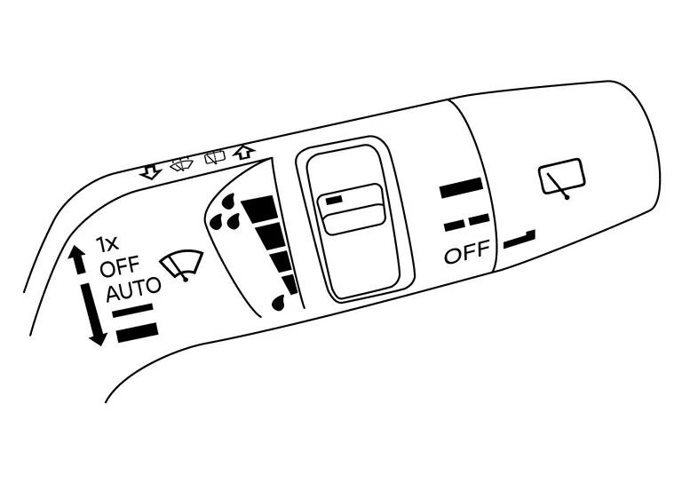
Wiper and Washer Switch
-
Wiper and washer switch is integrated with the combination switch.
- Wiper switch with rain sensing front wipers:
FRONT WIPER BASIC OPERATION
-
BCM detects the combination switch (wiper and washer switch) condition by the combination switch reading function.
-
BCM transmits the front wiper request signal to the IPDM E/R via CAN communication depending on each operating condition of the front wiper.
-
IPDM E/R turns ON/OFF the integrated front wiper relay and the front wiper HIGH relay according to the front wiper request signal. IPDM E/R provides the power supply to operate the front wiper HI/LO operation.
FRONT WIPER LO OPERATION
-
BCM transmits the front wiper request signal (LOW) to the IPDM E/R via CAN communication according to the front wiper LO operating condition.
Front wiper LO operating condition:
-
Ignition switch ON
-
Front wiper switch LO or front wiper switch MIST (while pressing)
-
-
IPDM E/R turns ON the integrated front wiper relay according to the front wiper request signal (LOW).
FRONT WIPER HI OPERATION
-
BCM transmits the front wiper request signal (HIGH) to the IPDM E/R via CAN communication according to the front wiper HI operating condition.
Front wiper HI operating condition:
-
Ignition switch ON
-
Front wiper switch HI
-
-
IPDM E/R turns ON the integrated front wiper relay and the front wiper HIGH relay according to the front wiper request signal (HIGH).
FRONT WIPER INT OPERATION
-
BCM transmits the front wiper request signal (LOW) to the IPDM E/R via CAN communication depending on the front wiper INT operating condition and intermittent operation delay interval according to the wiper volume dial position.
Front wiper INT operating condition:
-
Ignition switch ON
-
Front wiper switch INT
-
-
IPDM E/R turns ON the integrated front wiper relay so that the front wiper is operated only once according to the front wiper request signal (LOW) and front wiper request signal (RETURN).
-
BCM detects stop position/except stop position of the front wiper motor according to the front wiper stop position signal received from the IPDM E/R via CAN communication.
-
BCM transmits the front wiper request signal (LOW) again after the intermittent operation delay interval.
NOTE:
The front wiper INT operation setting of the linked or not linked with Nissan Ariya vehicle speed can be changed by combination meter setting.
Front wiper intermittent operation with vehicle speed:
-
BCM calculates the intermittent operation delay interval from the following:
-
Nissan Ariya Vehicle speed signal
-
Wiper volume dial position
-
Intermittent operation delay Interval
Unit: Second
| Intermittent operation interval | Nissan Ariya Vehicle speed | ||||
| Accelerating |
0 ŌĆō 3.1 MPH (0 ŌĆō 5 km/h) |
3.1 ŌĆō 40.4 MPH (5 ŌĆō 65 km/h) |
40.4 MPH (65 km/h) or more |
||
| Decelerating |
0 ŌĆō 1.2 MPH (0 ŌĆō 2 km/h) |
1.2 ŌĆō 37.3 MPH (2 ŌĆō 60 km/h) |
37.3 MPH (60 km/h) or more |
||
|
Long Ōåæ Ōåō Short |
Wiper volume dial position | 1 | 21.0 | 7.5 | 4.5 |
| 2 | 11.2 | 4.0 | 2.4 | ||
| 3 | 5.6 | 2.0 | 1.2 | ||
| 4 | 2.8 | 1.0 | 0.6 | ||
| 5 | 1.4 | 0.5 | 0.3 | ||
Unit: Second
| Intermittent operation interval | |||
|
Long Ōåæ Ōåō Short |
Wiper volume dial position | 1 | 15.0 |
| 2 | 8.0 | ||
| 3 | 4.0 | ||
| 4 | 2.0 | ||
| 5 | 1.0 | ||
FRONT WIPER AUTO STOP OPERATION
Rain Detection
Rain level and sensor conditions are detected by rain and light sensor.
-
BCM transmits the vehicle conditions (vehicle speed, front wiper condition, rain and light sensor sensitivity setting, etc.) to the rain and light sensor via LIN communication.
-
Rain and light sensor judges a wiping speed for front wiper by rain condition and the Nissan Ariya vehicle conditions. It transmits the wiping speed request signal to the BCM via LIN communication.
Auto Wiping Operation
-
BCM receives the wiping speed request signal from the rain and light sensor via LIN communication.
-
BCM controls front wiper operation according to the wiping speed request signals. It transmits the front wiper request signals (LO or HI) to the IPDM E/R via CAN communication.
Front wiper AUTO operating condition:
-
Ignition switch ON
-
Front wiper switch AUTO
-
NOTE:
-
When the front wiper switch is turned to AUTO position, the front wiper operates once regardless of rainy conditions.
-
Factory setting of the front wiper AUTO operation is operation linked with rain sensor. Front wiper AUTO operation can be set to operation linked or not linked with rain sensor using CONSULT. Refer to CONSULT Function (BCM - WIPER)
| BCM determines rain and light sensor sensitivity according to wiper volume dial position. | |
|---|---|
| Wiper volume dial position | Sensitivity |
| 1. | High sensitivity |
| 2. | MediumŌłÆhigh sensitivity |
| 3. | MediumŌłÆlow sensitivity |
| 4. | Low sensitivity |
NOTE:
When the wiper volume dial position is turned up by 1 level under front wiper AUTO operating condition, the front wiper operates once.
Splash mode operation
The front wiper is operated at HI regardless of the wiper volume adjustment position when water drops are instantaneously sprayed over the windshield glass due to water splash from oncoming Nissan Ariya vehicles or other causes. After that, AUTO operation is performed depending on the amount of water drops.
SPLASH MODE OPERATION CONDITIONS:
-
Front wiper switch AUTO
-
Ignition switch ON
NOTE:
Splash mode is not operated and auto wiping operation is performed while the Nissan Ariya vehicle is stopped.
FRONT WIPER AUTO STOP OPERATION
-
BCM transmits the front wiper request signal (RETURN) to the IPDM E/R via CAN communication when the front wiper switch is turned OFF.
-
IPDM E/R detects the front wiper auto stop position signal from the front wiper motor to find out the front wiper motor position (stop position/except stop position).
-
When the IPDM E/R receives the front wiper request signal (RETURN) from the BCM and the front wiper motor position is not in the stop position, the IPDM E/R turns ON the front wiper relay until the front wiper motor returns to the stop position.
-
When the front wiper motor returns to the stop position, the IPDM E/R transmits front wiper status signal to the BCM via CAN communication.
-
When the BCM receives front wiper status signal from the IPDM E/R, the BCM transmits the front wiper request signal (STOP) to the IPDM E/R via CAN communication.
FRONT WIPER OPERATION LINKED WITH WASHER
-
BCM transmits the front wiper request signal (LO) to the IPDM E/R via CAN communication according to the washer linked operating condition of the front wiper.
-
BCM transmits the front wiper request signal (LO) so that the front wiper operates approximately two times when the front washer switch OFF signal is detected.
Washer linked operating condition of front wiper:
-
Ignition switch ON
-
Front washer switch ON (0.4 seconds or more)
-
-
IPDM E/R turns ON the integrated front wiper relay according to the front wiper request signal (LO).
-
The washer pump is supplied power and ground through the combination switch (wiper and washer switch) with the front washer switch ON.
WIPER LINKED AUTO LIGHTING FUNCTION
When lighting switch is in the AUTO position, front wiper operates, and then headlamps turn ON. Refer to System Description.
Rear Wiper and Washer System
System Description
SYSTEM DIAGRAM
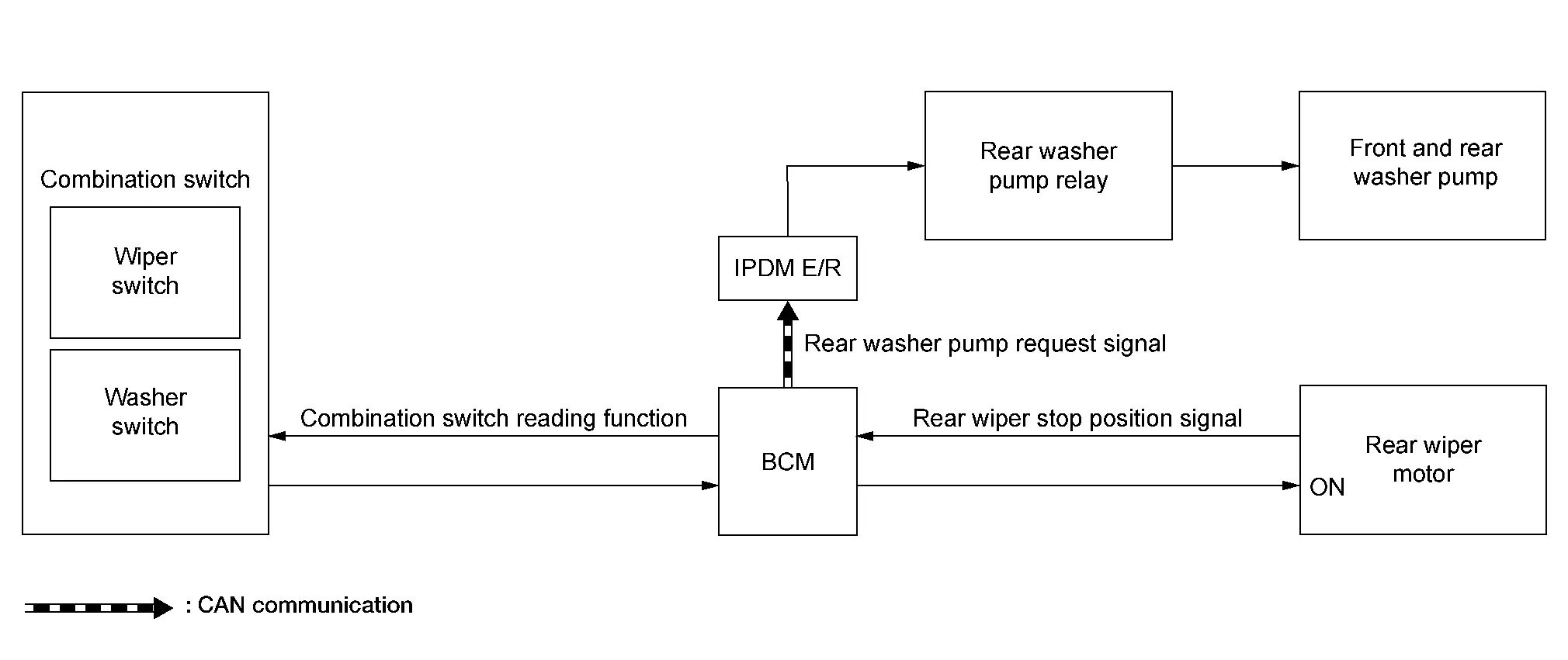
| Component | Function | |
|---|---|---|
| Rear wiper motor | Refer to Rear Wiper Motor. | |
| IPDM E/R | Controls the rear washer pump relay according to the request from the BCM via CAN communication. | |
| BCM | Supplies power to the rear wiper motor. | |
| Combination switch (wiper & washer switch) | Transmits the status of the combination switch (wiper and washer) to the BCM. | |
| Front and rear washer pump | Refer to Front And Rear Washer Pump. | |
| Rear washer pump relay | Controls front and rear washer pump according to the request from the IPDM E/R. | |
OUTLINE
The rear wiper is controlled by each function of BCM.
Control by BCM
-
Combination switch reading function
-
Rear wiper control function
SIGNAL TRANSMISSION FUNCTION LIST
| Signal name | Input | Output | Description |
|---|---|---|---|
| Rear washer pump request signal | BCM | IPDM E/R (CAN) | Transmits the rear washer pump request signal to IPDM E/R via CAN communication. |
| Combination switch signal | Combination switch (wiper and washer switch) | BCM | Transmits the combination switch signal to the BCM. |
| Rear wiper stop position signal | Rear wiper motor | BCM | Transmits the rear wiper stop position signal to the BCM. |
REAR WIPER BASIC OPERATION
-
BCM detects the combination switch condition by the combination switch reading function.
-
BCM controls the rear wiper to start or stop.
REAR WIPER ON OPERATION
-
BCM supplies power to the rear wiper motor according to the rear wiper ON operating condition.
Rear wiper ON operating condition
-
Ignition switch ON
-
Rear wiper switch ON
-
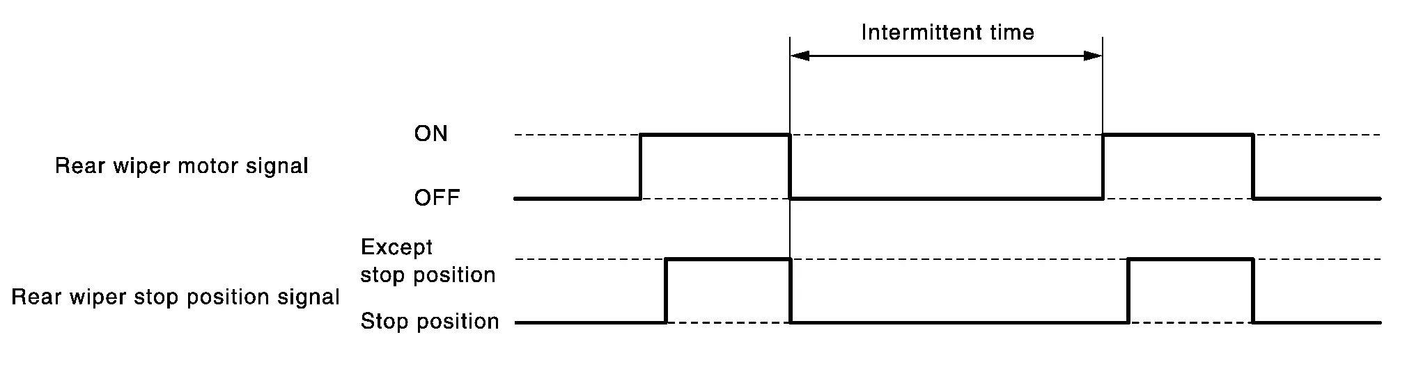
REAR WIPER INT OPERATION
-
BCM supplies power to the rear wiper motor according to the INT operating condition.
Rear wiper INT operating condition
-
Ignition switch ON
-
Rear wiper switch INT
-
-
BCM controls the rear wiper to operate once.
-
BCM detects the rear wiper motor stop position.
-
BCM supplies power to the rear wiper motor again after an intermittent stop of the rear wiper motor.
REAR WIPER AUTO STOP OPERATION
-
BCM stops supplying power to the rear wiper motor when the rear wiper switch is turned OFF.
-
BCM reads a rear wiper stop position signal from the rear wiper motor to detect a rear wiper motor position.
-
When the rear wiper motor is at other than the stopping position, BCM continues to supply power to the rear wiper motor until it returns to the stop position.
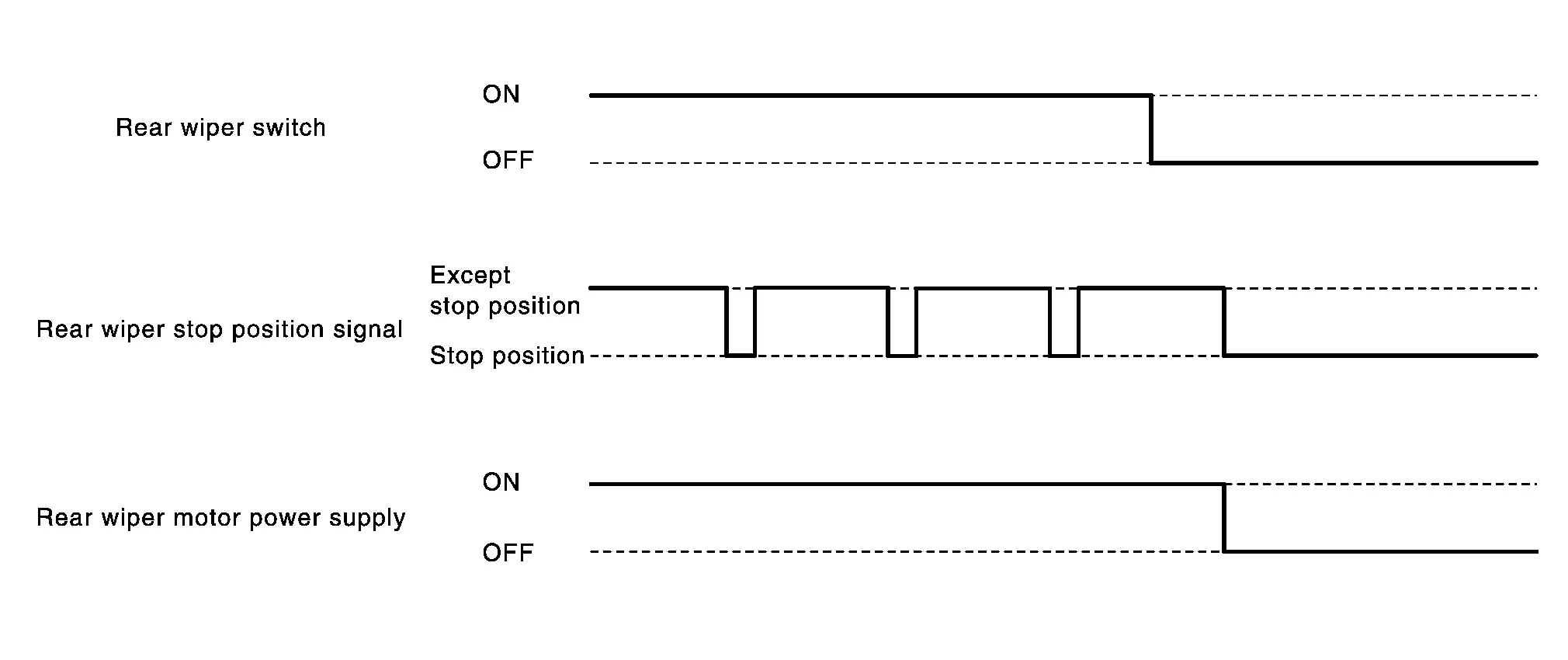
NOTE:
BCM stops supplying power to the rear wiper motor when the ignition switch is placed OFF.
REAR WIPER OPERATION LINKED WITH WASHER
-
BCM supplies power to the rear wiper motor according to the washer linked operating condition of rear wiper. When the rear washer switch is turned OFF, BCM controls rear wiper to operate approximately 3 times.
Washer linked operating condition of rear wiper
-
Ignition switch ON
-
Rear washer switch ON
-
-
BCM transmits the rear washer pump request signal to IPDM E/R via CAN communication.
-
IPDM E/R turns ON/OFF the rear washer pump relay according to the rear washer pump request signal. IPDM E/R provides the power supply and ground to operate the front and rear washer pump.
REAR WIPER OPERATION LINKED WITH REVERSE
-
BCM controls rear wiper to INT operating according to the conditions of rear wiper operation linked with reverse.
Condition of rear wiper operation linked with reverse
-
Ignition switch ON
-
Front wiper switch: LO, HI, INT or AUTO
-
Rear wiper switch OFF
-
Shift lever ŌĆ£RŌĆØ
-
-
When shift lever is shifted to ŌĆ£RŌĆØ, electric shift control module transmits reverse switch signal to BCM via CAN communication, and then operates rear wiper motor.
NOTE:
Rear wiper operation linked with reverse can be set ON or OFF through the combination meter.
Information Display (combination Meter)
Washer Fluid Warning
NOTE:
Washer fluid warning is only applied in Canada.
DESIGN/PURPOSE
Washer fluid warning reminds driver the washer fluid is insufficient.
| Symbol | Message |
|---|---|
|
|
Low Washer Fluid |

SYNCHRONIZATION WITH MASTER WARNING LAMP
Not applicable
SYSTEM DIAGRAM
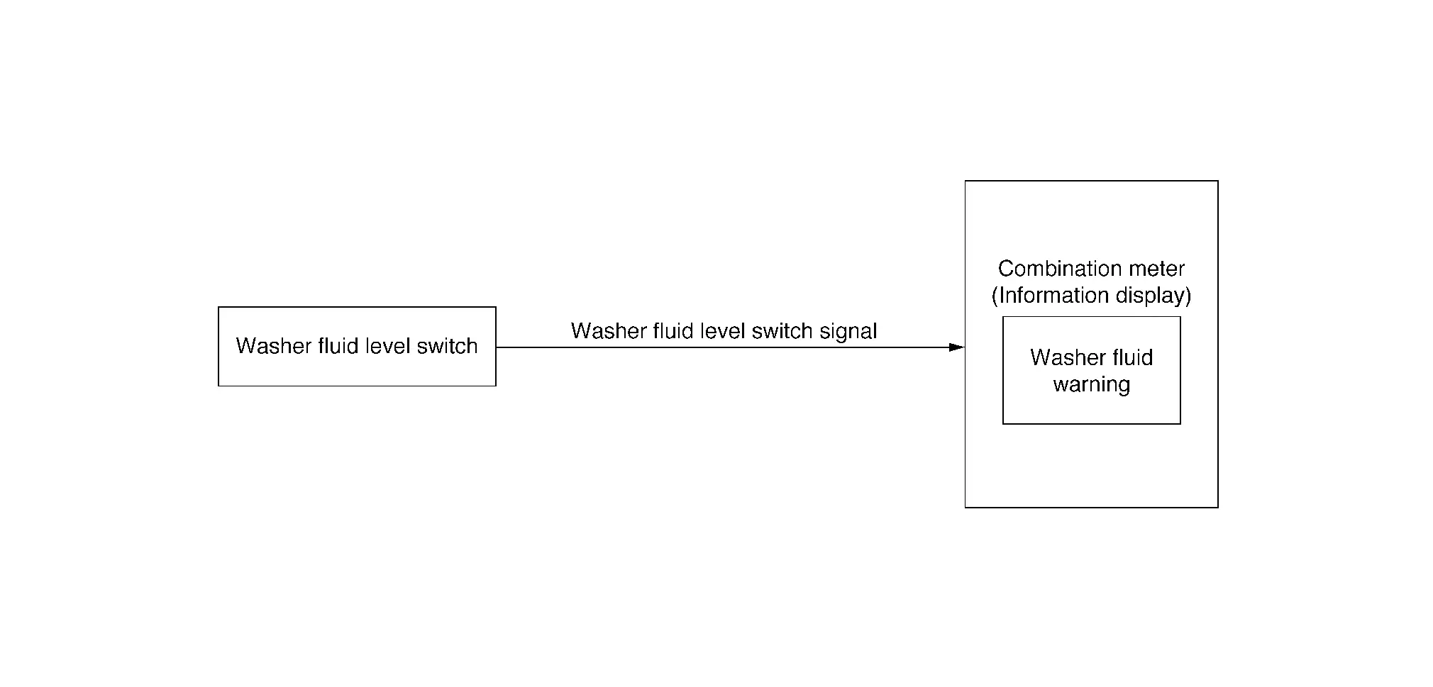
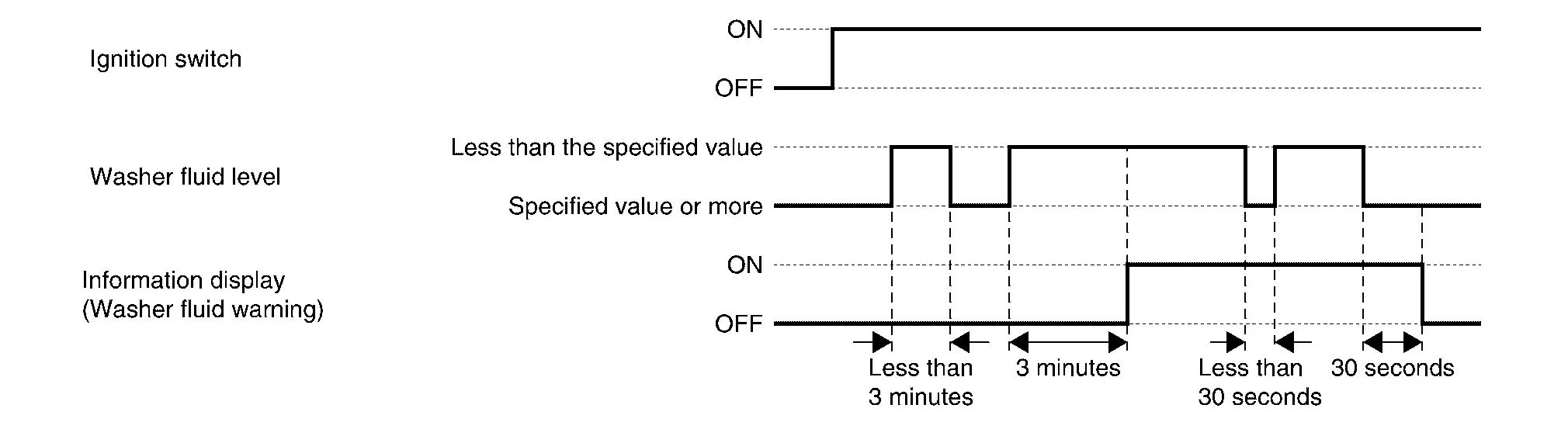
SIGNAL PATH
-
When washer fluid level is low, the washer fluid level switch turns ON and transmits the washer fluid level switch signal to the combination meter.
-
Combination meter display washer fluid warning according to washer fluid level switch signal.
WARNING/INDICATOR OPERATING CONDITION
When all of the conditions listed below are satisfied:
-
Ignition switch is ON.
-
Washer fluid is insufficient. (Washer fluid level switch is ON and 3 minutes are passed).
WARNING/INDICATOR CANCEL CONDITION
When any of the condition listed below is satisfied:
-
Ignition switch is OFF.
-
After refill the washer fluid. (Washer fluid level switch is OFF and 30 seconds are passed).
TIMING CHART
Warning/indicator/chime List
Warning/Indicator (Information Display)
| Item | Reference |
|---|---|
|
Washer fluid warning (Only applied in Canada) |
Refer to Washer Fluid Warning. |
Other materials:
U1ca2-08 Lin Communication 3
DTC Description
DTC DETECTION LOGIC DTC No.
CONSULT screen terms
(Trouble diagnosis content) DTC detection condition
U1CA2-08
LIN communication 3
(Local interconnect network communication 3)
Diagnosis condition
Ignition switch ON
Signal (Terminal)
LIN (door motor) signal
...
Brake system
Braking precautions
Basic information
The brake system uses two independent
hydraulic circuits. If one circuit fails,
braking at two wheels will still be available.
Vacuum assisted brakes
The brake booster enhances braking force
using engine vacuum. If the engine stops,
you can still brake by press ...
Variable Compression Ratio Control Shaft 2 Rotation Angle Sensor
Component Inspection
CHECK VCR CONTROL SHAFT 2 ROTATION ANGLE SENSOR
Turn ignition switch OFF.
Disconnect VCR control shaft 2 rotation angle sensor harness connector.
Check the continuity between VCR control shaft 2 rotation angle sensor harness connectors.
VCR control shaft 2 rota ...