Nissan Rogue (T33) 2021-Present Service Manual: Basic Inspection :: Diagnosis and Repair Work Flow
Work Flow
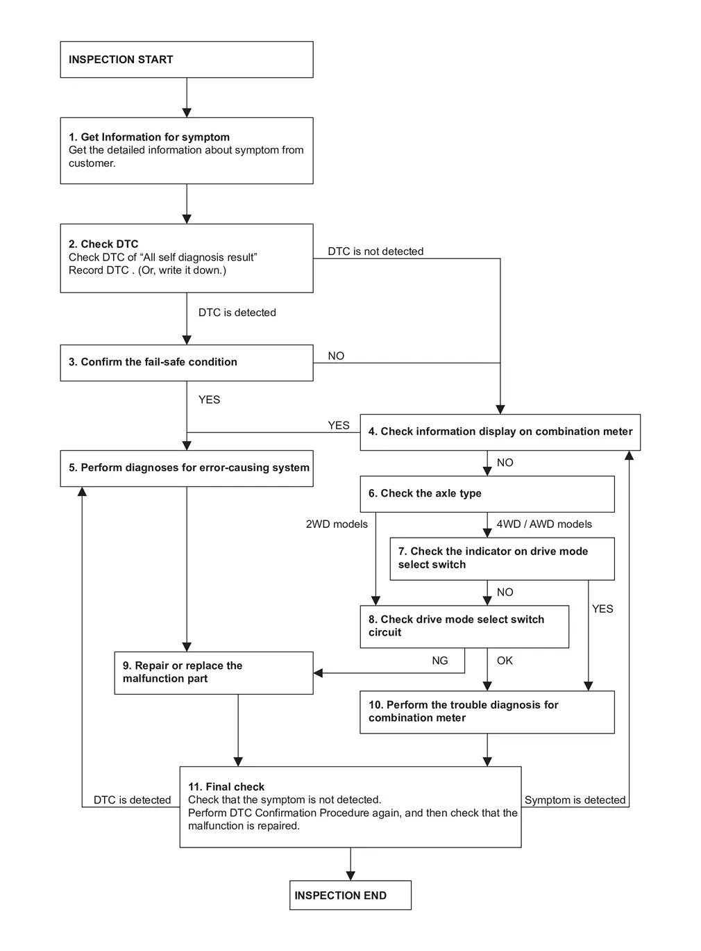
OVERALL SEQUENCE
DETAILED FLOW
GET INFORMATION FOR SYMPTOM
-
Get the detailed information about symptom from customer.
-
Check the drive mode indicator on the meter appeared.
-
Check the Drive mode indicator on the meter changed when operates the drive mode select switch.
>>
GO TO 2.
CHECK THE DTC
 With CONSULT
-
Check DTC of âAll self diagnosis resultâ.
-
Perform the following procedure if DTC is displayed.
-
Record DTC and freeze frame data. (Or, write it down.)
-
Are any DTCs detected?
YES>>GO TO 3.
NO>>GO TO 4.
CONFIRM THE FAIL-SAFE CONDITION
Confirm the fail-safe condition of detected DTC. Refer to Fail-safe.
Are there any DTCs that causes drive mode selector function is suspended?
YES>>GO TO 5.
NO>>GO TO 4.
CHECK INFORMATION DISPLAY ON COMBINATION METER
-
Ignition switch OFF and wait at least 10 seconds.
-
Ignition switch ON.
-
Check that STANDARD is displayed on the information display screen of the combination meter. (2WD models)
-
Check that AUTO is displayed on the information display screen of the combination meter. (AWD models)
-
Check that the view of information display change when switching up and down the drive mode select switch. (2WD models)
-
Check that the view of information display change when switching left and right the drive mode select switch. (AWD models)
Is the inspection result normal?
YES>>GO TO 5.
NO>>GO TO 6.
PERFORM DIAGNOSES FOR ERROR-CAUSING SYSTEM
With CONSULT
Perform the trouble diagnosis of components that DTC indicated.
>>
GO TO 9.
CHECK THE AXLE TYPE
Check the axle type.
2WD models>>
GO TO 8.
AWD models>>GO TO 7.
CHECK THE INDICATOR ON DRIVE MODE SELECT SWITCH (AWD MODELS)
-
Ignition switch OFF and wait at least 10 seconds.
-
Ignition switch ON.
-
Check the indicator of AUTO on drive mode select switch indicator.
-
Check the illuminated position changes according to the operation when switching the drive mode select switch.
Is the inspection result normal?
YES>>GO TO 10.
NO>>GO TO 8.
CHECK DRIVE MODE SELECT SWITCH CIRCUIT
Check drive mode select switch circuit. Refer to Diagnosis Procedure.
Is the inspection result normal?
YES>>GO TO 10.
NO>>GO TO 9.
REPAIR OR REPLACE THE MALFUNCTION PART
Repair or replace the malfunctioning part.
>>
GO TO 11.
CHECK COMBINATION METER
Check the COMBINATION METER.
-
Full TFT meter: Refer to On Board Diagnosis Function.
-
7 inch information display: Refer to On Board Diagnosis Function.
>>
GO TO 11.
FINAL CHECK
-
Check that the symptom is not detected.
-
Perform DTC Confirmation Procedure again, and then check that the malfunction is repaired.
Is DTC detected and/or does symptom remain?
YES (DTC is detected)>>GO TO 5.
YES (Symptom remains)>>GO TO 4.
NO>>INSPECTION END
Other materials:
Side Radar Front Lh
Reference Value
VALUES ON THE DIAGNOSIS TOOL Monitor item Condition Value/Status
Horizontal alignment value
When the ignition switch ON and the side radar adjustment is completed
Displays the horizontal alignment value
TERMINAL LAYOUTPHYSICAL VALUES
Terminal No.
(Wire color) Descr ...
Commande de feux de dÃĐtresse
Appuyez sur cette commande pour signaler aux autres usagers que vous devez vous arrÊter ou stationner en urgence. Tous les clignotants du Nissan Rogue fonctionnent alors simultanÃĐment.
AVERTISSEMENT
En cas dâarrÊt dâurgence, garez le vÃĐhicule le plus loin possible de la circulatio ...
Freins
Informations de base
Si le systÃĻme de freinage du Nissan Rogue ne fonctionne pas correctement, faites-le contrÃīler sans dÃĐlai par un concessionnaire NISSAN.
Freins à rattrapage automatique d'usure
Le Nissan Rogue est ÃĐquipÃĐ de freins à rattrapage automatique dâusure. Les freins à disq ...