
Nissan Rogue (T33) 2021-Present Service Manual: Side Radar Front Lh
Reference Value
VALUES ON THE DIAGNOSIS TOOL
| Monitor item | Condition | Value/Status | |
|---|---|---|---|
| Horizontal alignment value | When the ignition switch ON and the side radar adjustment is completed | Displays the horizontal alignment value | |
TERMINAL LAYOUT
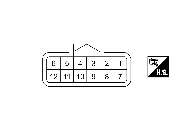
PHYSICAL VALUES
|
Terminal No. (Wire color) | Description | Condition | Value (Approx.) | ||
|---|---|---|---|---|---|
| + | – | Signal name | Input/Output | ||
|
1 (BR) |
— | CAN communication-H | — | — | — |
|
2 (V) |
— | CAN communication-L | — | — | — |
|
10 (LA/B) |
Ground | Ground | — | Ignition switch ON | 0 V |
|
12 (LA/Y) |
10 (LA/B) |
Ignition power supply | Input | Ignition switch ON | Battery voltage |
Fail-safe
Refer to Fail-safe (Side Radar).
DTC Inspection Priority Chart
If some DTCs are displayed at the same time, perform inspections one by one based on the following priority chart.
| Priority | Detected items (DTC) |
|---|---|
| 1 |
|
| 2 |
|
DTC Index
×:Applicable
| DTC |
Items (CONSULT screen terms) | Fail-safe | Reference | ||||||
|---|---|---|---|---|---|---|---|---|---|
| Nissan Ariya Vehicle speed & vehicle-to-vehicle control function | Lane keep function*1 | Lane keep function*2 | Lane change support function | Overtaking support function | Route driving support function | ||||
| C1E40 | 44 | Control unit | × | × | × | × | × | × | DTC Description |
| 45 | × | × | × | × | × | × | DTC Description | ||
| 46 | × | × | × | × | × | × | DTC Description | ||
| 47 | × | × | × | × | × | × | DTC Description | ||
| 48 | × | × | × | × | × | × | DTC Description | ||
| 49 | × | × | × | × | × | × | DTC Description | ||
| 4B | × | × | × | × | × | × | DTC Description | ||
| C1E41 | 12 | Incorrect installation location | × | × | × | × | × | × | DTC Description |
| C1E50 | 54 | Side radar alignment | × | × | × | × | × | × | DTC Description |
| C1E52 | 16 | Side radar malfunction | × | × | × | × | × | × | DTC Description |
| 17 | × | × | × | × | × | × | DTC Description | ||
| C1E53 | 55 | Configuration unfinished | × | × | × | × | × | × | DTC Description |
| U2148 | 81 | CAN communication error (brake control unit) | × | × | × | × | × | × | DTC Description |
| 82 | × | × | × | × | × | × | DTC Description | ||
| 83 | × | × | × | × | × | × | DTC Description | ||
| 87 | × | × | × | × | × | × | DTC Description | ||
| U214F | 81 | CAN communication error (BCM) | × | × | × | × | × | × | DTC Description |
| 82 | × | × | × | × | × | × | DTC Description | ||
| 83 | × | × | × | × | × | × | DTC Description | ||
| 87 | × | × | × | × | × | × | DTC Description | ||
| U2156 | 81 | CAN communication error (steering angle sensor) | × | × | × | × | × | × | DTC Description |
| 87 | × | × | × | × | × | × | DTC Description | ||
| U215B | 81 | CAN communication error (IPDM E/R) | × | × | × | × | × | × | DTC Description |
| 82 | × | × | × | × | × | × | DTC Description | ||
| 83 | × | × | × | × | × | × | DTC Description | ||
| 87 | × | × | × | × | × | × | DTC Description | ||
| U2A09 | 88 | Communication Bus Off ITS5-FD | × | × | × | × | × | × | DTC Description |
*1: ProPILOT Assist 2.1 display is green
*2: ProPILOT Assist 2.1 display is blue
Other materials:
Système d'essuie-glace automatique avec détecteur de pluie du Nissan Rogue
Le Nissan Rogue est doté d'une technologie de détection de précipitations intelligente. Ce système d'essuie-glace automatique, assisté par un capteur de pluie optique situé sur la partie supérieure du pare-brise (derrière le rétroviseur intérieur), est capable d'activer les balais sa ...
B2601-42 Memory Failure for Firmware Over the Air
DTC Description
DTC DETECTION LOGIC DTC No. CONSULT screen terms DTC detected condition
B2601-42
Memory failure for firmware over the air
Diagnosis condition
When ignition switch is ON.
Signal (terminal)
—
Threshold
Errors are detected in the memory for software auto ...
Dtc/circuit Diagnosis. Eps Warning Lamp
Component Function Check
CHECK THE ILLUMINATION OF THE ELECTRIC POWER STEERING WARNING LAMP
Check that the electric power steering warning lamp turns ON when
ignition switch ON. Then, electric power steering warning lamp turns OFF
after the engine is started.
Is the inspection result normal?
...