Nissan Rogue (T33) 2021-Present Service Manual: Side Radar Rear Lh
Reference Value
VALUES ON THE DIAGNOSIS TOOL
 NOTE:
NOTE:
The following table includes information (items) inapplicable to this Nissan Ariya vehicle. For information (items) applicable to this vehicle, refer to CONSULT display items.
| Monitor item | Condition | Value/Status | |
|---|---|---|---|
| BSW select | Ignition switch ON | When the BSW is ON | On |
| When the BSW is OFF | Off | ||
| RCTA select | Ignition switch ON | When the RCTA is ON | On |
| When the RCTA is OFF | Off | ||
| Horizontal alignment value | Ignition switch ON | (-5 deg) – (+5 deg) | |
| Vertical alignment value |
The item is displayed, but it is not used |
— | |
TERMINAL LAYOUT
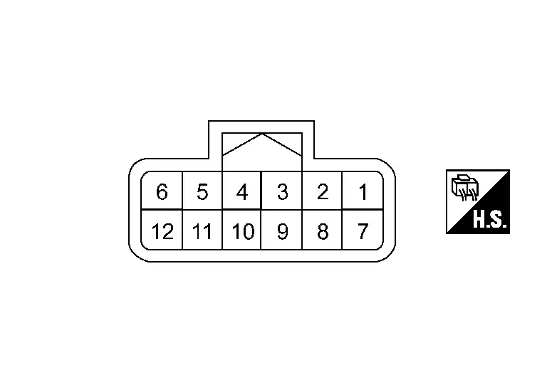
PHYSICAL VALUES
|
Terminal No. (Wire color) | Description | Condition |
Value (Approx.) | ||
|---|---|---|---|---|---|
| + | – | Signal name | Input/Output | ||
|
1 (BR) |
10 (LA/B) |
ITS CAN communication-H | — | — | — |
|
2 (LG) |
ITS CAN communication-L | — | — | — | |
|
4 (LA/P) |
BSW indicator signal | Output | Approx. 2 sec. after ignition switch OFF ⇒ ON (bulb check) | 12 V | |
|
7 (LG) |
CAN L | — | — | — | |
|
8 (BR) |
CAN H | — | — | — | |
|
10 (LA/B) |
Ground | Ground | — | Ignition switch ON | 0 V |
|
11 (LA/B) |
10 (LA/B) |
Switching signal | — | — | 0 V |
|
12 (GR) |
Ignition power supply | Input | Ignition switch ON | Battery voltage | |
Fail-safe
Refer to Fail-safe (Side Radar).
DTC Inspection Priority Chart
If some DTCs are displayed at the same time, perform inspections one by one based on the following priority chart.
| Priority | Detected items (DTC) |
|---|---|
| 1 |
|
| 2 |
|
| 3 |
|
DTC Index
Ă—: Applicable
| DTC |
Items (CONSULT screen terms) | Fail-safe | Reference | |||||||||
|---|---|---|---|---|---|---|---|---|---|---|---|---|
| Nissan Ariya Vehicle speed & vehicle-to-vehicle control function | Lane keep function*1 | Lane keep function*2 | Lane change support function | Overtaking support function | Route driving support function | BSW | I-BSI | RCTA | ||||
| C1E00 | 44 | Control unit | Ă— | Ă— | Ă— | Ă— | Ă— | Ă— | Ă— | Ă— | Ă— | DTC Description |
| 45 | Ă— | Ă— | Ă— | Ă— | Ă— | Ă— | Ă— | Ă— | Ă— | DTC Description | ||
| 46 | Ă— | Ă— | Ă— | Ă— | Ă— | Ă— | Ă— | Ă— | Ă— | DTC Description | ||
| 47 | Ă— | Ă— | Ă— | Ă— | Ă— | Ă— | Ă— | Ă— | Ă— | DTC Description | ||
| 48 | Ă— | Ă— | Ă— | Ă— | Ă— | Ă— | Ă— | Ă— | Ă— | DTC Description | ||
| 49 | Ă— | Ă— | Ă— | Ă— | Ă— | Ă— | Ă— | Ă— | Ă— | DTC Description | ||
| 4B | Ă— | Ă— | Ă— | Ă— | Ă— | Ă— | Ă— | Ă— | Ă— | DTC Description | ||
| 97 | Ă— | Ă— | Ă— | Ă— | Ă— | Ă— | Ă— | Ă— | Ă— | DTC Description | ||
| C1E01 | 12 | Incorrect installation location | Ă— | Ă— | Ă— | Ă— | Ă— | Ă— | Ă— | Ă— | Ă— | DTC Description |
| 67 | Ă— | Ă— | Ă— | Ă— | Ă— | Ă— | Ă— | Ă— | Ă— | DTC Description | ||
| C1E10 | 54 | Radar off-center | Ă— | Ă— | Ă— | Ă— | Ă— | Ă— | Ă— | Ă— | Ă— | DTC Description |
| 78 | Ă— | Ă— | Ă— | Ă— | Ă— | Ă— | Ă— | Ă— | Ă— | DTC Description | ||
| C1E11 | 97 | RADAR BLOCKED | Ă— | Ă— | Ă— | Ă— | Ă— | Ă— | Ă— | Ă— | Ă— | DTC Description |
| C1E12 | 16 | Power supply circuit | Ă— | Ă— | Ă— | Ă— | Ă— | Ă— | Ă— | Ă— | Ă— | DTC Description |
| 17 | Ă— | Ă— | Ă— | Ă— | Ă— | Ă— | Ă— | Ă— | Ă— | DTC Description | ||
| C1E13 | 55 | Configuration unfinished | Ă— | Ă— | Ă— | Ă— | Ă— | Ă— | Ă— | Ă— | Ă— | DTC Description |
| U1B26 | 15 | BSW indicator | Ă— | Ă— | Ă— | Ă— | Ă— | Ă— | Ă— | Ă— | Ă— | DTC Description |
| U1B2E | 86 | CAN comm err | Ă— | Ă— | Ă— | Ă— | Ă— | Ă— | Ă— | Ă— | Ă— | DTC Description |
| 87 | Ă— | Ă— | Ă— | Ă— | Ă— | Ă— | Ă— | Ă— | Ă— | DTC Description | ||
| U2104 | 87 | CAN comm err (active steering) | Ă— | Ă— | Ă— | Ă— | Ă— | Ă— | Ă— | Ă— | Ă— | DTC Description |
| U2141 | 87 | CAN comm err (TCM) | Ă— | Ă— | Ă— | Ă— | Ă— | Ă— | Ă— | Ă— | Ă— | DTC Description |
| U2148 | 87 | CAN comm err (brake control unit) | Ă— | Ă— | Ă— | Ă— | Ă— | Ă— | Ă— | Ă— | Ă— | DTC Description |
| U214E | 87 | CAN comm err (combination meter) | Ă— | Ă— | Ă— | Ă— | Ă— | Ă— | Ă— | Ă— | Ă— | DTC Description |
| U214F | 87 | CAN comm err (BCM) | Ă— | Ă— | Ă— | Ă— | Ă— | Ă— | Ă— | Ă— | Ă— | DTC Description |
| U2152 | 87 | CAN comm err (ADAS control unit) | Ă— | Ă— | Ă— | Ă— | Ă— | Ă— | Ă— | Ă— | Ă— | DTC Description |
| U2154 | 87 | CAN comm err (MIU) | Ă— | Ă— | Ă— | Ă— | Ă— | Ă— | Ă— | Ă— | Ă— | DTC Description |
| U2156 | 87 | CAN comm err (steering angle sensor) | Ă— | Ă— | Ă— | Ă— | Ă— | Ă— | Ă— | Ă— | Ă— | DTC Description |
| U215B | 87 | CAN comm err (IPDM E/R) | Ă— | Ă— | Ă— | Ă— | Ă— | Ă— | Ă— | Ă— | Ă— | DTC Description |
| U216E | 87 | CAN comm err (side radar) | Ă— | Ă— | Ă— | Ă— | Ă— | Ă— | Ă— | Ă— | Ă— | DTC Description |
| U2A08 | 88 | CAN comm err (ITS3/5-CAN Bus Off) | Ă— | Ă— | Ă— | Ă— | Ă— | Ă— | Ă— | Ă— | Ă— | DTC Description |
*1: ProPILOT Assist 2.1 display is green
*2: ProPILOT Assist 2.1 display is blue
Other materials:
Input Speed Sensor
Exploded View
1.
O-ring
2.
Input speed sensor
3.
Transaxle assembly
: N·m (kg-m, in-lb) : Always replace after every disassembly. : Apply petroleum jelly.
Removal and Installation
REMOVAL Never Reuse These Parts Part Code For additional information:
Seal-O-ring
31051 ...
If your vehicle overheats
WARNING
Never continue driving if your vehicle overheats — this can lead to engine failure or even a vehicle fire.
Never open the hood if steam is coming out.
Never remove the radiator or coolant reservoir cap when the engine is hot. Pressurized coolant can spray out and cause serious ...
Dtc/circuit Diagnosis. U2a06-88 Comm Bus Off V-Fd
DTC Description
DESCRIPTIONCAN (Controller Area Network) is a serial
communication line for real time applications. It is an on-Nissan Ariya
vehicle multiplex communication line with high data communication speed
and excellent error detection ability. Modern Nissan Ariya vehicle is
equipped ...