Nissan Rogue (T33) 2021-Present Service Manual: Front Camera Unit
Reference Value
VALUES ON THE DIAGNOSIS TOOL
 NOTE:
NOTE:
The following table includes information (items) inapplicable to this Nissan Ariya vehicle. For information (items) applicable to this vehicle, refer to CONSULT display items.
| Monitor item | Condition | Value/Status | ||
|---|---|---|---|---|
| AIMING DONE | Ignition switch ON | When the camera aiming is not completed | 0 | |
| When the camera aiming is completed | 1 | |||
| AIMING RESULT | Ignition switch ON | When the camera aiming is NG completed | 0 | |
| When the camera aiming is normal completed | 1 | |||
| AIM NG REASON | Ignition switch ON | When the camera aiming is normal completed | 0 | |
| When the front camera unit has an internal communication error | 1 | |||
| When the front camera unit has an internal data error | 2 | |||
| When the front camera unit has a target information error | 3 | |||
| When the front camera unit has a aiming mode error | 4 | |||
| When a timeout occurs | 5 | |||
| When the front camera unit cannot transition to aiming mode | 6 | |||
| When the front camera unit has a memory writing error | 7 | |||
| When the condition of the front camera unit installation is not correct | 8 | |||
| When all correction values are outside the threshold | 9 | |||
| When NG reason is unknown | 16 | |||
| When the front camera unit cannot detect the target | 18 | |||
| When the roll angle is outside the threshold | 19 | |||
| When the front camera unit cannot calculate the aiming correction values | 20 | |||
| When the front camera unit cannot read the distance to target board | 21 | |||
| When the entered "Dt" value is not correct | 22 | |||
| When the entered "Ts" value is not correct | 23 | |||
| When the yaw correction values are outside the threshold | 24 | |||
| When the pitch correction values are outside the threshold | 25 | |||
| When several targets are detected | 26 | |||
| When an error is detected during the camera aiming | 27 | |||
| When NG reason is unknown | 255 | |||
| AIM YAW | Ignition switch ON | 0 ┬▒ 3.0 deg | ||
| AIM ROL | Ignition switch ON | 0 ┬▒ 3.0 deg | ||
| AIM PIT | Ignition switch ON | 0 ┬▒ 3.0 deg | ||
| FCTRY AIM YAW | Ignition switch ON | 0 ┬▒ 3.0 deg | ||
| FCTRY AIM ROL | Ignition switch ON | 0 ┬▒ 3.0 deg | ||
| FCTRY AIM PIT | Ignition switch ON | 0 ┬▒ 3.0 deg | ||
| Configuration result 1 | Ignition switch ON | When the configuration is completed | Finished | |
| When the configuration is not completed | Unfnshd | |||
| Configuration status | Ignition switch ON | When the configuration is completed | OK | |
| When the configuration is not completed | NG1 | |||
| When the threshold is out of range | NG2 | |||
| When the front camera unit has internal malfunction | NG3 | |||
| When the front camera unit has internal malfunction | NG4 | |||
| When the front camera unit has communication error | NG5 | |||
| When the front camera unit fails to write | NG6 | |||
| Heater system | Ignition switch ON | Off | ||
| ECU power supply voltage | Ignition switch ON | 6.4 ŌĆō 16 V | ||
| Configuration type | Ignition switch ON | Type2 | ||
| Engine type | Ignition switch ON | Gasoline | ||
| Manufacturer | Ignition switch ON | Nissan | ||
| Nissan Ariya Vehicle width | Ignition switch ON | 1.84 | ||
| Transmission type | Ignition switch ON | AT/CVT | ||
| ALH | Ignition switch ON | When the ALH system is installed | On | |
| When the ALH system is not installed | Off | |||
| HBA function | Ignition switch ON | When the HBA is ON | On | |
| When the HBA is OFF | Off | |||
| Camera image bottom | Ignition switch ON | 24 pixel | ||
| Camera height | Ignition switch ON | 1,501 mm | ||
| Camera distance 1 | Ignition switch ON | 895 mm | ||
| Camera distance 2 | Ignition switch ON | 943 mm | ||
| Camera offset | Ignition switch ON | 0 mm | ||
| Camera pitch | Ignition switch ON | 0.609 deg | ||
| Nissan Ariya Vehicle speed | While driving | Almost the same speed as speedometer indication | ||
| ECU operating state | Ignition switch ON | When the front camera unit has any malfunction | Unknown | |
|
When the front camera unit is waiting to start (The display changes depending on the standby state) |
PENDING | |||
| State4 | ||||
| State7 | ||||
| State8 | ||||
| State9 | ||||
| State10 | ||||
| State11 | ||||
| State12 | ||||
| State13 | ||||
| When the front camera unit is operating normally | State3 | |||
|
When the front camera unit is operating in a mode other than normal (The display changes depending on the operating status) |
State5 | |||
| State6 | ||||
| State14 | ||||
| State15 | ||||
| State16 | ||||
| State17 | ||||
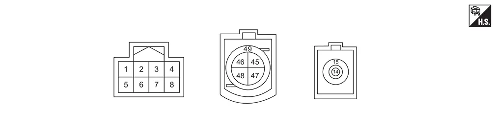
TERMINAL LAYOUT (WITHOUT ProPILOT ASSIST 2.1)

PHYSICAL VALUES (WITHOUT ProPILOT ASSIST 2.1)
|
Terminal No. (Wire color) | Description | Condition |
Value (Approx.) | ||
|---|---|---|---|---|---|
| + | ŌĆō | Signal name | Input/Output | ||
|
3 (LA/R)*1 (R)*2 |
8 (LA/B)*1 (B)*2 |
ITS CAN communication-L | ŌĆö | ŌĆö | ŌĆö |
|
5 (LA/SB)*1 (SB)*2 |
Ignition power supply | Input | Ignition switch ON | Battery voltage | |
|
7 (LA/BR)*1 (BR)*2 |
ITS CAN communication-H | ŌĆö | ŌĆö | ŌĆö | |
|
8 (LA/B)*1 (B)*2 |
Ground | Ground | ŌĆö | Ignition switch ON | 0 V |
|
9 (SHIELD) |
ŌĆö | Shield | ŌĆö | ŌĆö | ŌĆö |
|
10 (Y) |
Ethernet(+) | ŌĆö | ŌĆö | ŌĆö | |
|
11 (G) |
Ethernet(-) | ŌĆö | ŌĆö | ŌĆö | |
*1: Japan production
*2: USA production
TERMINAL LAYOUT (WITH ProPILOT ASSIST 2.1)
|
Terminal No. (Wire color) | Description | Condition |
Value (Approx.) | ||
|---|---|---|---|---|---|
| + | ŌĆō | Signal name | Input/Output | ||
|
1 (LA/BG) |
4 (P) |
Heater power supply | Output | Heater ON | Battery voltage |
|
3 (R) |
ŌĆö | ITS CAN communication-L | ŌĆö | ŌĆö | ŌĆö |
|
4 (P) |
Ground | Heater ground | ŌĆö | Ignition switch ON | 0 V |
|
5 (LA/BR) |
Ground | Ignition power supply | ŌĆö | Ignition switch ON | Battery voltage |
|
7 (BR) |
ŌĆö | ITS CAN communication-H | ŌĆö | ŌĆö | ŌĆö |
|
8 (LA/B) |
Ground | Ground | Input | Ignition switch ON | 0 V |
|
47 (Y) |
ŌĆö | Ethernet(+) | ŌĆö | ŌĆö | ŌĆö |
|
48 (G) |
Ethernet(-) | ŌĆö | ŌĆö | ŌĆö | |
|
49 (SHIELD) |
ŌĆö | Shield | ŌĆö | ŌĆö | ŌĆö |
|
14 (V) |
Ground | LVDS (Driver assistance camera) | ŌĆö | ŌĆö | ŌĆö |
|
15 (SHIELD) |
ŌĆö | Shield | ŌĆö | ŌĆö | ŌĆö |
Fail-safe
Refer to Fail-safe (Front Camera Unit).
DTC Inspection Priority Chart
If some DTCs are displayed at the same time, perform inspections one by one based on the following priority chart.
| Priority | Detected items (DTC) |
|---|---|
| 1 |
|
| 2 |
|
DTC Index
├Ś:Applicable
| DTC |
Items (CONSULT screen terms) | Fail-safe | Reference | ||||||||||||||
|---|---|---|---|---|---|---|---|---|---|---|---|---|---|---|---|---|---|
| Nissan Ariya Vehicle-to-vehicle distance control mode*1 | Steering wheel assistance function*1 | Conventional (fixed speed) cruise control mode*1 | Nissan Ariya Vehicle speed & vehicle-to-vehicle control function*2 | Lane keep function*2,3 | Lane keep function*2,4 | Lane change support function*2 | Overtaking support function*2 | Route driving support function*2 | FEB | LDW | LDP | Blind Spot Intervention | TSR | ||||
| C2500 | 49 | Camera unit malfunction | ├Ś | ├Ś | ├Ś | ├Ś | ├Ś | ├Ś | ├Ś | ├Ś | ├Ś | ├Ś | ├Ś | ├Ś | ├Ś | ├Ś | DTC Description |
| C2501 | 4B | Front camera unit | ├Ś | ├Ś | ├Ś | ├Ś | ├Ś | ├Ś | ├Ś | ├Ś | ├Ś | ├Ś | ├Ś | ├Ś | ├Ś | ├Ś | DTC Description |
| C2502 | 55 | Configuration data error | ├Ś | ├Ś | ├Ś | ├Ś | ├Ś | ├Ś | ├Ś | ├Ś | ├Ś | ├Ś | ├Ś | ├Ś | ├Ś | ├Ś | DTC Description |
| 92 | ├Ś | ├Ś | ├Ś | ├Ś | ├Ś | ├Ś | ├Ś | ├Ś | ├Ś | ├Ś | ├Ś | ├Ś | ├Ś | ├Ś | DTC Description | ||
| C2503 | 54 | Camera aiming incomplete | ├Ś | ├Ś | ├Ś | ├Ś | ├Ś | ├Ś | ├Ś | ├Ś | ├Ś | ├Ś | ├Ś | ├Ś | ├Ś | ├Ś | DTC Description |
| C2505 | 92 | Front camera unit | ├Ś | ├Ś | ├Ś | ├Ś | ├Ś | ├Ś | ├Ś | ├Ś | ├Ś | ├Ś | ├Ś | ├Ś | ├Ś | ├Ś | DTC Description |
| C2507 | 16 | Power supply circuit | ├Ś | ├Ś | ├Ś | ├Ś | ├Ś | ├Ś | ├Ś | ├Ś | ├Ś | ├Ś | ├Ś | ├Ś | ├Ś | ├Ś | DTC Description |
| 17 | ├Ś | ├Ś | ├Ś | ├Ś | ├Ś | ├Ś | ├Ś | ├Ś | ├Ś | ├Ś | ├Ś | ├Ś | ├Ś | ├Ś | DTC Description | ||
| C2520 | 87 | BCM | ├Ś | ├Ś | ├Ś | ├Ś | ├Ś | ├Ś | ├Ś | ├Ś | ├Ś | ├Ś | ├Ś | ├Ś | ├Ś | ├Ś | DTC Description |
| C2521 | 82 | ECM | ├Ś | ├Ś | ├Ś | ├Ś | ├Ś | ├Ś | ├Ś | ├Ś | ├Ś | ├Ś | ├Ś | ├Ś | ├Ś | ├Ś | DTC Description |
| 83 | ├Ś | ├Ś | ├Ś | ├Ś | ├Ś | ├Ś | ├Ś | ├Ś | ├Ś | ├Ś | ├Ś | ├Ś | ├Ś | ├Ś | DTC Description | ||
| 86 | ├Ś | ├Ś | ├Ś | ├Ś | ├Ś | ├Ś | ├Ś | ├Ś | ├Ś | ├Ś | ├Ś | ├Ś | ├Ś | ├Ś | DTC Description | ||
| C2522 | 87 | ABS | ├Ś | ├Ś | ├Ś | ├Ś | ├Ś | ├Ś | ├Ś | ├Ś | ├Ś | ├Ś | ├Ś | ├Ś | ├Ś | ├Ś | DTC Description |
| C2523 | 87 | Combination meter | ├Ś | ├Ś | ├Ś | ├Ś | ├Ś | ├Ś | ├Ś | ├Ś | ├Ś | ├Ś | ├Ś | ├Ś | ├Ś | ├Ś | DTC Description |
| C2525 | 86 | AV control unit | ├Ś | ├Ś | ├Ś | ├Ś | ├Ś | ├Ś | ├Ś | ├Ś | ├Ś | ├Ś | ├Ś | ├Ś | ├Ś | ├Ś | DTC Description |
| 87 | ├Ś | ├Ś | ├Ś | ├Ś | ├Ś | ├Ś | ├Ś | ├Ś | ├Ś | ├Ś | ├Ś | ├Ś | ├Ś | ├Ś | DTC Description | ||
| C2526 | 82 | ADAS control unit | ├Ś | ├Ś | ├Ś | ├Ś | ├Ś | ├Ś | ├Ś | ├Ś | ├Ś | ├Ś | ├Ś | ├Ś | ├Ś | ├Ś | DTC Description |
| 86 | ├Ś | ├Ś | ├Ś | ├Ś | ├Ś | ├Ś | ├Ś | ├Ś | ├Ś | ├Ś | ├Ś | ├Ś | ├Ś | ├Ś | DTC Description | ||
| 87 | ├Ś | ├Ś | ├Ś | ├Ś | ├Ś | ├Ś | ├Ś | ├Ś | ├Ś | ├Ś | ├Ś | ├Ś | ├Ś | ├Ś | DTC Description | ||
| C2527 | 82 | TCM | ├Ś | ├Ś | ├Ś | ├Ś | ├Ś | ├Ś | ├Ś | ├Ś | ├Ś | ├Ś | ├Ś | ├Ś | ├Ś | ├Ś | DTC Description |
| 83 | ├Ś | ├Ś | ├Ś | ├Ś | ├Ś | ├Ś | ├Ś | ├Ś | ├Ś | ├Ś | ├Ś | ├Ś | ├Ś | ├Ś | DTC Description | ||
| 86 | ├Ś | ├Ś | ├Ś | ├Ś | ├Ś | ├Ś | ├Ś | ├Ś | ├Ś | ├Ś | ├Ś | ├Ś | ├Ś | ├Ś | DTC Description | ||
| C2528 | 87 | IPDM E/R | ├Ś | ├Ś | ├Ś | ├Ś | ├Ś | ├Ś | ├Ś | ├Ś | ├Ś | ├Ś | ├Ś | ├Ś | ├Ś | ├Ś | DTC Description |
| C2529 | 86 | Air bag diagnosis sensor unit | ├Ś | ├Ś | ├Ś | ├Ś | ├Ś | ├Ś | ├Ś | ├Ś | ├Ś | ├Ś | ├Ś | ├Ś | ├Ś | ├Ś | DTC Description |
| 87 | ├Ś | ├Ś | ├Ś | ├Ś | ├Ś | ├Ś | ├Ś | ├Ś | ├Ś | ├Ś | ├Ś | ├Ś | ├Ś | ├Ś | DTC Description | ||
| C252A | 86 | Steering angle sensor | ├Ś | ├Ś | ├Ś | ├Ś | ├Ś | ├Ś | ├Ś | ├Ś | ├Ś | ├Ś | ├Ś | ├Ś | ├Ś | ├Ś | DTC Description |
| 87 | ├Ś | ├Ś | ├Ś | ├Ś | ├Ś | ├Ś | ├Ś | ├Ś | ├Ś | ├Ś | ├Ś | ├Ś | ├Ś | ├Ś | DTC Description | ||
| C2531 | 86 | CCM | ├Ś | ├Ś | ├Ś | ├Ś | ├Ś | ├Ś | ├Ś | ├Ś | ├Ś | ├Ś | ├Ś | ├Ś | ├Ś | ├Ś | DTC Description |
| 87 | ├Ś | ├Ś | ├Ś | ├Ś | ├Ś | ├Ś | ├Ś | ├Ś | ├Ś | ├Ś | ├Ś | ├Ś | ├Ś | ├Ś | DTC Description | ||
| C2544 | 82 | Around view control unit | ├Ś | ├Ś | ├Ś | ├Ś | ├Ś | ├Ś | ├Ś | ├Ś | ├Ś | ├Ś | ├Ś | ├Ś | ├Ś | ├Ś | DTC Description |
| 83 | ├Ś | ├Ś | ├Ś | ├Ś | ├Ś | ├Ś | ├Ś | ├Ś | ├Ś | ├Ś | ├Ś | ├Ś | ├Ś | ├Ś | DTC Description | ||
| 86 | ├Ś | ├Ś | ├Ś | ├Ś | ├Ś | ├Ś | ├Ś | ├Ś | ├Ś | ├Ś | ├Ś | ├Ś | ├Ś | ├Ś | DTC Description | ||
| 87 | ├Ś | ├Ś | ├Ś | ├Ś | ├Ś | ├Ś | ├Ś | ├Ś | ├Ś | ├Ś | ├Ś | ├Ś | ├Ś | ├Ś | DTC Description | ||
| C2545 | 82 | ADAS control unit | ├Ś | ├Ś | ├Ś | ├Ś | ├Ś | ├Ś | ├Ś | ├Ś | ├Ś | ├Ś | ├Ś | ├Ś | ├Ś | ├Ś | DTC Description |
| 83 | ├Ś | ├Ś | ├Ś | ├Ś | ├Ś | ├Ś | ├Ś | ├Ś | ├Ś | ├Ś | ├Ś | ├Ś | ├Ś | ├Ś | DTC Description | ||
| 86 | ├Ś | ├Ś | ├Ś | ├Ś | ├Ś | ├Ś | ├Ś | ├Ś | ├Ś | ├Ś | ├Ś | ├Ś | ├Ś | ├Ś | DTC Description | ||
| 87 | ├Ś | ├Ś | ├Ś | ├Ś | ├Ś | ├Ś | ├Ś | ├Ś | ├Ś | ├Ś | ├Ś | ├Ś | ├Ś | ├Ś | DTC Description | ||
| C2570 | 4B | Front camera unit | ├Ś | ├Ś | ├Ś | ├Ś | ├Ś | ├Ś | ├Ś | ├Ś | ├Ś | ├Ś | ├Ś | ├Ś | ├Ś | ├Ś | DTC Description |
| C2571 | 78 | Front camera unit | ├Ś | ├Ś | ├Ś | ├Ś | ├Ś | ├Ś | ├Ś | ├Ś | ├Ś | ├Ś | ├Ś | ├Ś | ├Ś | ├Ś | DTC Description |
| C2572 | 71 | Front camera unit | ├Ś | ├Ś | ├Ś | ├Ś | ├Ś | ├Ś | ├Ś | ├Ś | ├Ś | ├Ś | ├Ś | ├Ś | ├Ś | ├Ś | DTC Description |
| C2572 | 97 | Front camera unit | ├Ś | ├Ś | ├Ś | ├Ś | ├Ś | ├Ś | ├Ś | ├Ś | ├Ś | ├Ś | ├Ś | ├Ś | ├Ś | ├Ś | DTC Description |
| C2575 | 92 | Front camera unit | ├Ś | ├Ś | ├Ś | ├Ś | ├Ś | ├Ś | ├Ś | ├Ś | ├Ś | ├Ś | ├Ś | ├Ś | ├Ś | ├Ś | DTC Description |
| C2577 | 11 | Heater_element | Ńā╝ | Ńā╝ | Ńā╝ | Ńā╝ | Ńā╝ | Ńā╝ | Ńā╝ | Ńā╝ | Ńā╝ | Ńā╝ | Ńā╝ | Ńā╝ | Ńā╝ | Ńā╝ | DTC Description |
| 13 | Ńā╝ | Ńā╝ | Ńā╝ | Ńā╝ | Ńā╝ | Ńā╝ | Ńā╝ | Ńā╝ | Ńā╝ | Ńā╝ | Ńā╝ | Ńā╝ | Ńā╝ | Ńā╝ | DTC Description | ||
| 19 | Ńā╝ | Ńā╝ | Ńā╝ | Ńā╝ | Ńā╝ | Ńā╝ | Ńā╝ | Ńā╝ | Ńā╝ | Ńā╝ | Ńā╝ | Ńā╝ | Ńā╝ | Ńā╝ | DTC Description | ||
| U0077 | 00 | Control module communication Bus E Off | ├Ś | ├Ś | ├Ś | ├Ś | ├Ś | ├Ś | ├Ś | ├Ś | ├Ś | ├Ś | ├Ś | ├Ś | ├Ś | ├Ś | DTC Description |
| U0078 | 00 | Control module communication Bus F Off | ├Ś | ├Ś | ├Ś | ├Ś | ├Ś | ├Ś | ├Ś | ├Ś | ├Ś | ├Ś | ├Ś | ├Ś | ├Ś | ├Ś | DTC Description |
| U2104 | 87 | CAN communication error (active steering) | ├Ś | ├Ś | ├Ś | ├Ś | ├Ś | ├Ś | ├Ś | ├Ś | ├Ś | ├Ś | ├Ś | ├Ś | ├Ś | ├Ś | DTC Description |
| U2140 | 87 | CAN communication error (ECM) | ├Ś | ├Ś | ├Ś | ├Ś | ├Ś | ├Ś | ├Ś | ├Ś | ├Ś | ├Ś | ├Ś | ├Ś | ├Ś | ├Ś | DTC Description |
| U2141 | 87 | CAN communication error (TCM) | ├Ś | ├Ś | ├Ś | ├Ś | ├Ś | ├Ś | ├Ś | ├Ś | ├Ś | ├Ś | ├Ś | ├Ś | ├Ś | ├Ś | DTC Description |
| U2143 | 87 | CAN communication error (VCM/HCM) | ├Ś | ├Ś | ├Ś | ├Ś | ├Ś | ├Ś | ├Ś | ├Ś | ├Ś | ├Ś | ├Ś | ├Ś | ├Ś | ├Ś | DTC Description |
| U2148 | 87 | CAN communication error (brake control unit) | ├Ś | ├Ś | ├Ś | ├Ś | ├Ś | ├Ś | ├Ś | ├Ś | ├Ś | ├Ś | ├Ś | ├Ś | ├Ś | ├Ś | DTC Description |
| U214E | 87 | CAN communication error (combination meter) | ├Ś | ├Ś | ├Ś | ├Ś | ├Ś | ├Ś | ├Ś | ├Ś | ├Ś | ├Ś | ├Ś | ├Ś | ├Ś | ├Ś | DTC Description |
| U214F | 87 | CAN communication error (BCM) | ├Ś | ├Ś | ├Ś | ├Ś | ├Ś | ├Ś | ├Ś | ├Ś | ├Ś | ├Ś | ├Ś | ├Ś | ├Ś | ├Ś | DTC Description |
| U2150 | 87 | CAN communication error (AIRBAG) | ├Ś | ├Ś | ├Ś | ├Ś | ├Ś | ├Ś | ├Ś | ├Ś | ├Ś | ├Ś | ├Ś | ├Ś | ├Ś | ├Ś | DTC Description |
| U2152 | 87 | CAN communication error (ADAS control unit) | ├Ś | ├Ś | ├Ś | ├Ś | ├Ś | ├Ś | ├Ś | ├Ś | ├Ś | ├Ś | ├Ś | ├Ś | ├Ś | ├Ś | DTC Description |
| U2153 | 87 | CAN communication error (HVAC) | ├Ś | ├Ś | ├Ś | ├Ś | ├Ś | ├Ś | ├Ś | ├Ś | ├Ś | ├Ś | ├Ś | ├Ś | ├Ś | ├Ś | DTC Description |
| U2154 | 87 | CAN communication error (MIU) | ├Ś | ├Ś | ├Ś | ├Ś | ├Ś | ├Ś | ├Ś | ├Ś | ├Ś | ├Ś | ├Ś | ├Ś | ├Ś | ├Ś | DTC Description |
| U2156 | 87 | CAN communication error (steering angle sensor) | ├Ś | ├Ś | ├Ś | ├Ś | ├Ś | ├Ś | ├Ś | ├Ś | ├Ś | ├Ś | ├Ś | ├Ś | ├Ś | ├Ś | DTC Description |
| U215B | 87 | CAN communication error (IPDM E/R) | ├Ś | ├Ś | ├Ś | ├Ś | ├Ś | ├Ś | ├Ś | ├Ś | ├Ś | ├Ś | ├Ś | ├Ś | ├Ś | ├Ś | DTC Description |
| U276B | 88 | Ethernet circuit | ├Ś | ├Ś | ├Ś | ├Ś | ├Ś | ├Ś | ├Ś | ├Ś | ├Ś | ├Ś | ├Ś | ├Ś | ├Ś | ├Ś | DTC Description |
| U2A07 | 88 | CAN communication circuit | ├Ś | ├Ś | ├Ś | ├Ś | ├Ś | ├Ś | ├Ś | ├Ś | ├Ś | ├Ś | ├Ś | ├Ś | ├Ś | ├Ś | DTC Description |
*1: With ProPILOT Assist 1.1, Without ProPILOT Assist 2.1
*2: With ProPILOT Assist 2.1
*3: ProPILOT Assist 2.1 display is green
*4: ProPILOT Assist 2.1 display is blue
Other materials:
Power Supply and Ground Circuit
Side Radar Front Lh
Diagnosis Procedure
CHECK FUSE
Check that the following fuse is not blown:
Signal name Fuse No.
Ignition power supply
9 (10 A)
Is the fuse blown?
YES>>
Replace the blown fuse after repairing the affected circuit.
NO>>
GO TO 2.
CHECK POWER SU ...
Symptom Diagnosis. Door Does Not Lock/unlock with Door Request Switch and Intelligent Key
Description
All doors do not lock/unlock using door request switch.SYMPTOM TABLE (BOTH INTELLIGENT KEYS HAVE THE SAME SYMPTOMS) Door lock operation (remote keyless entry)
Door lock operation (request switch of front/rear/back door) or
trunk/back door open operation (opener switch of trunk/back ...
Fuel Injector Relay
Component Inspection
CHECK FUEL INJECTOR RELAY
Turn ignition switch OFF.
Remove fuel injector relay. Refer to Component Parts Location.
Check the continuity between fuel injector relay terminals as per the following conditions.
Fuel injector relay Condition Continuity
+ ŌłÆ
...