Nissan Rogue (T33) 2021-Present Service Manual: Removal and Installation :: Front Wiper
Exploded View
Removal
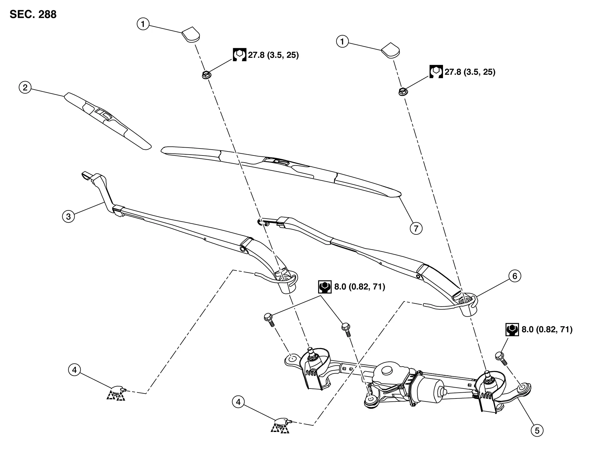
| 1. | Front wiper arm cap | 2. | Front wiper blade RH | 3. | Front wiper arm RH |
| 4. | Tube connector | 5. | Front wiper drive assembly | 6. | Front wiper arm LH |
| 7. | Front wiper blade LH | — | — | — | — |
 |
: Pawl | ||||
 |
: N·m (kg-m, in-lb) | ||||
 |
: N·m (kg-m, ft-lb) | ||||
Disassembly
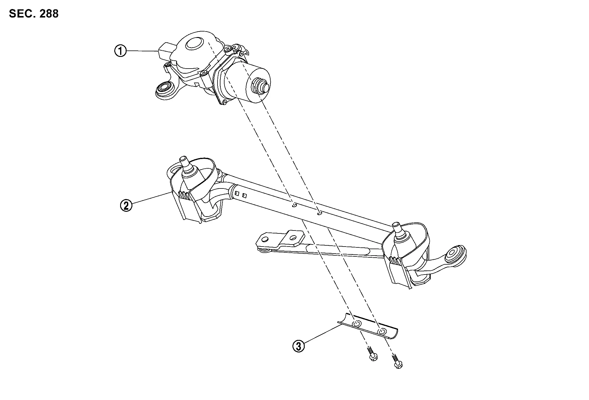
| 1. | Front wiper motor | 2. | Front wiper linkage assembly | 3. | Front wiper motor bracket |
Wiper Arm
Removal and Installation
CAUTION:
Clean the windshield glass and front wiper refill so that the windshield glass may not be damaged by dust, etc.
REMOVAL
Operate front wiper to auto stop position. Refer to System Description.
Full open hood assembly.
Remove front wiper arm cap.

Disconnect washer tube from tube connector  .
.
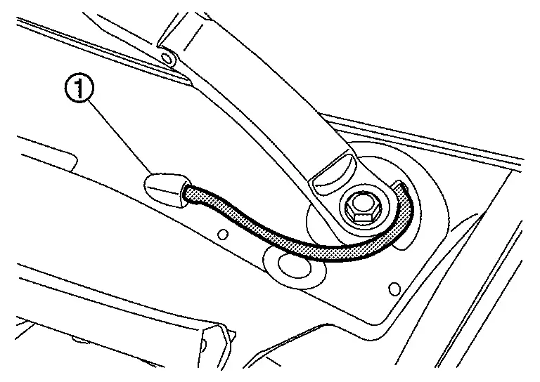
Remove front wiper arm mounting nut  .
.

Remove front wiper arm.
INSTALLATION
Note the following items, and then install in the reverse order of removal.
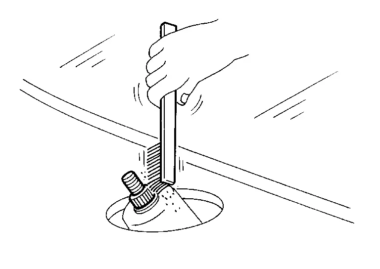
CAUTION:
-
Clean front wiper arm installation location as shown in the figure, and then fully insert front wiper arm to prevent nut from being loosened by shakiness.
-
Before installation, operate front wiper to the auto stop position.
-
When installation, install so that it is within the specified position. And after installation, operate front wiper, and then check that front wiper blades stop at the specified position. Refer to Adjustment.
Adjustment
WIPER BLADE POSITION ADJUSTMENT
Clearance between the end of cowl top cover/front fender cover and the top of front wiper blade center.
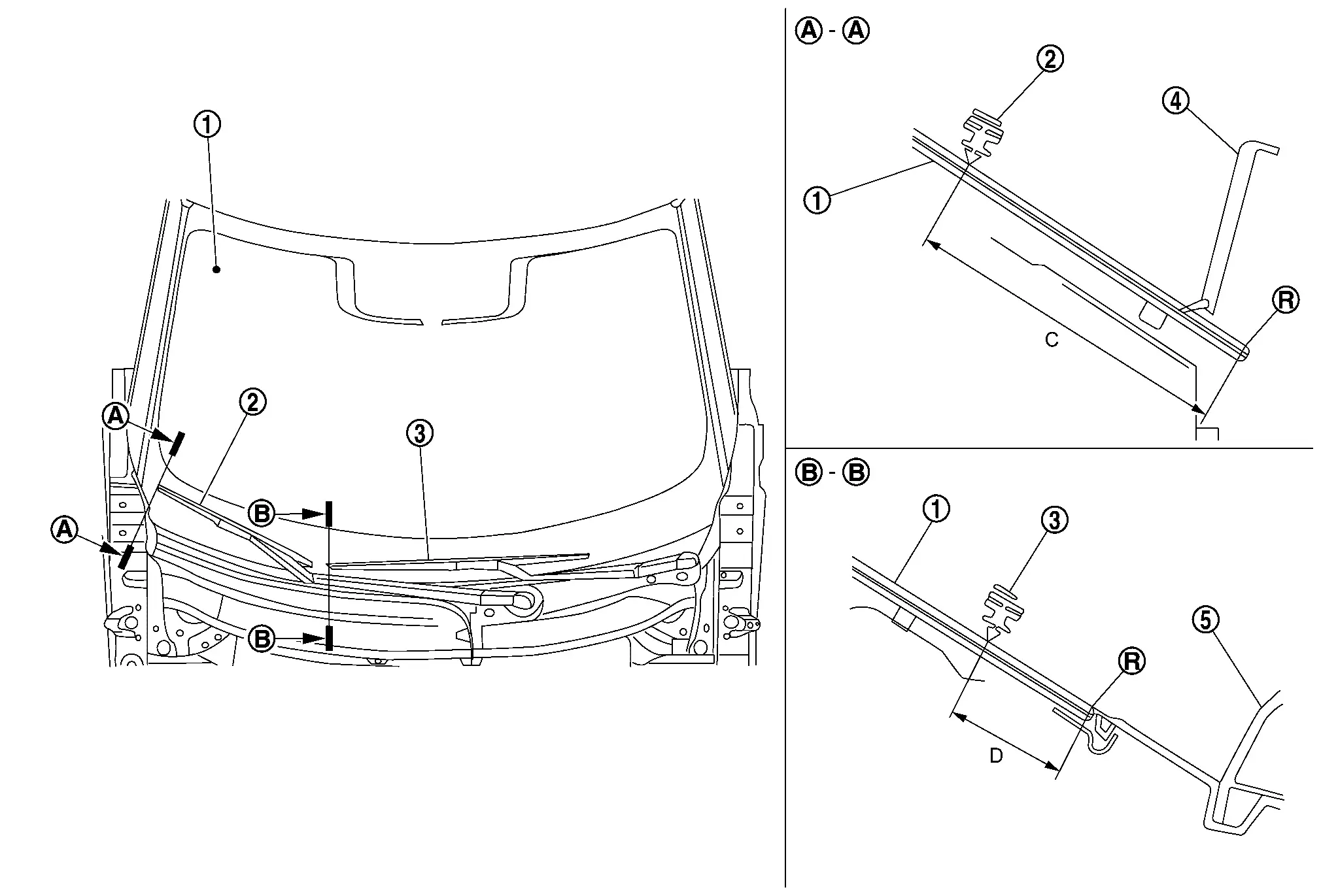
| 1. | Windshield glass | 2. | Front wiper blade RH | 3. | Front wiper blade LH |
| 4. | Front fender cover RH | 5. | Cowl top cover | — | — |
| R. | : R end | — | — | — | — |
| C | : 74.5 ± 7.5 mm (2.9 ± 0.30 in) |
| D | : 27 ± 7.5 mm (1.06 ± 0.30 in) |
 NOTE:
NOTE:
Perform measurement of clearance to the vertical direction of wiper blade.
Wiper Blade
Removal and Installation
CAUTION:
Clean windshield glass and front wiper refill so that windshield glass may not be damaged by dust, etc.
REMOVAL
Operate front wiper to auto stop position. Refer to System Description.
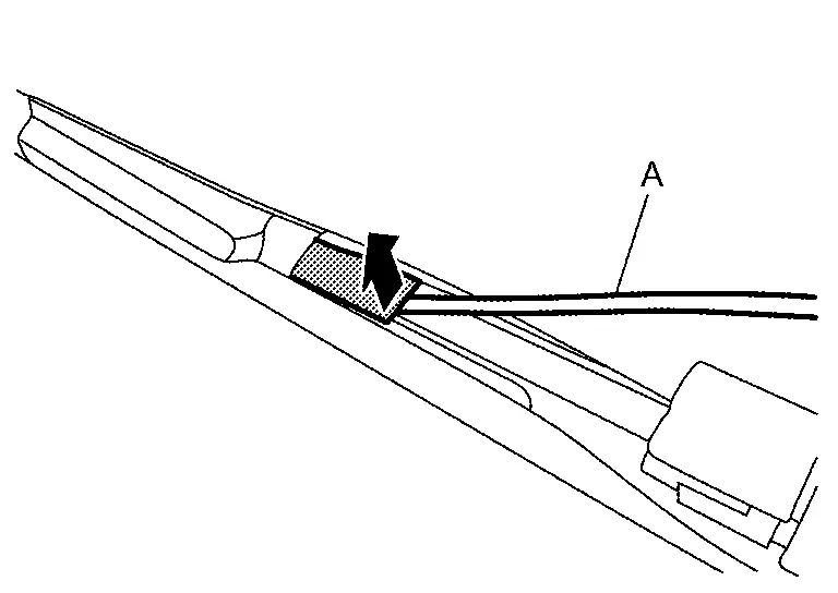
Lift up front wiper arm, and then lock back front wiper arm.
Unlock cover of front wiper blade using a remover tool (A) as shown by the arrow in the figure.
Slide wiper blade according to the numerical order 1→2 as shown in the figure from front wiper arm, and then remove front wiper blade.
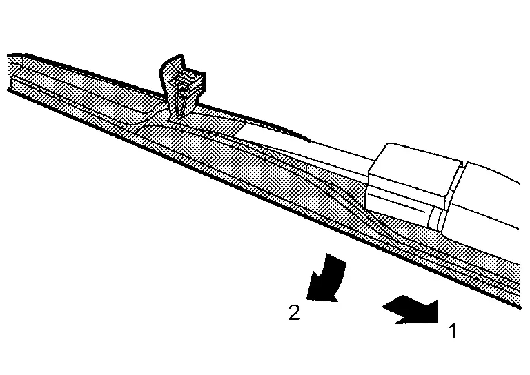
CAUTION:
After front wiper blade is removed, wrap front wiper arm with a shop cloth and fold it down so that front wiper arm does not fall against and damage windshield glass.
INSTALLATION
Install in the reverse order of removal.
Wiper Drive Assembly
Removal and Installation
REMOVAL
Remove cowl top cover. Refer to Removal and Installation.
Disconnect front wiper motor harness connector .
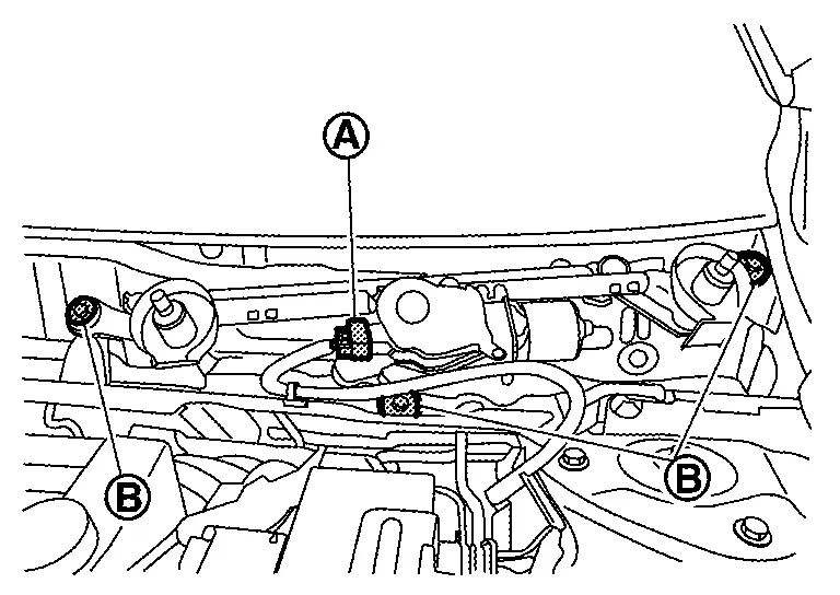
Remove front wiper drive assembly mounting bolts  , and then remove front wiper drive assembly.
INSTALLATION
Note the following item, and then install in the reverse order of removal.
CAUTION:
-
When installing, temporarily tighten all mounting bolts, and then tighten bolts to specified torque. Refer to Exploded View.
-
When front wiper drive assembly is replaced, before installing front wiper arm, operate front wipers, set front wiper motor to the auto stop position, and then install front wiper arms.
Disassembly and Assembly
DISASSEMBLY
Remove front wiper drive assembly. Refer to Removal and Installation.
Remove front wiper motor mounting bolts, and then remove front wiper motor and front wiper motor bracket from front wiper linkage assembly.
ASSEMBLY
Note the following items, and assembly in the reverse order of disassembly.
CAUTION:
When front wiper motor is replaced, before installing front wiper arm, operate front wipers, set front wiper motor to the auto stop position, and then install front wiper arms.
Other materials:
System
I-Fcw
System Description
SYSTEM DIAGRAM Component Description
ABS actuator and electric unit (control unit)
ABS Actuator and Electric Unit (Control Unit)
Combination meter (FULL TFT METER)
Combination Meter
Combination meter (7 INCH INFORMATION DISPLAY)
Combination Meter
...
Other supplemental front-impact air bag precautions
WARNING
Do not place any objects on the steering wheel pad or instrument panel. Do not place objects between any occupant and the steering wheel or instrument panel. These may turn into dangerous projectiles if the front air bags deploy.
Do not place sharp-edged objects or heavy items on ...
P06b0 Sensor Power Supply 1
DTC Description
DESCRIPTIONECM supplies a voltage of 5 V to some of the
sensors systematically divided into 3 groups, respectively.
Accordingly, when a short circuit develops in a sensor power source, a
malfunction may occur simultaneously in the sensors belonging to the
same group as the s ...