Nissan Rogue (T33) 2021-Present Service Manual: System
I-Fcw
System Description
SYSTEM DIAGRAM
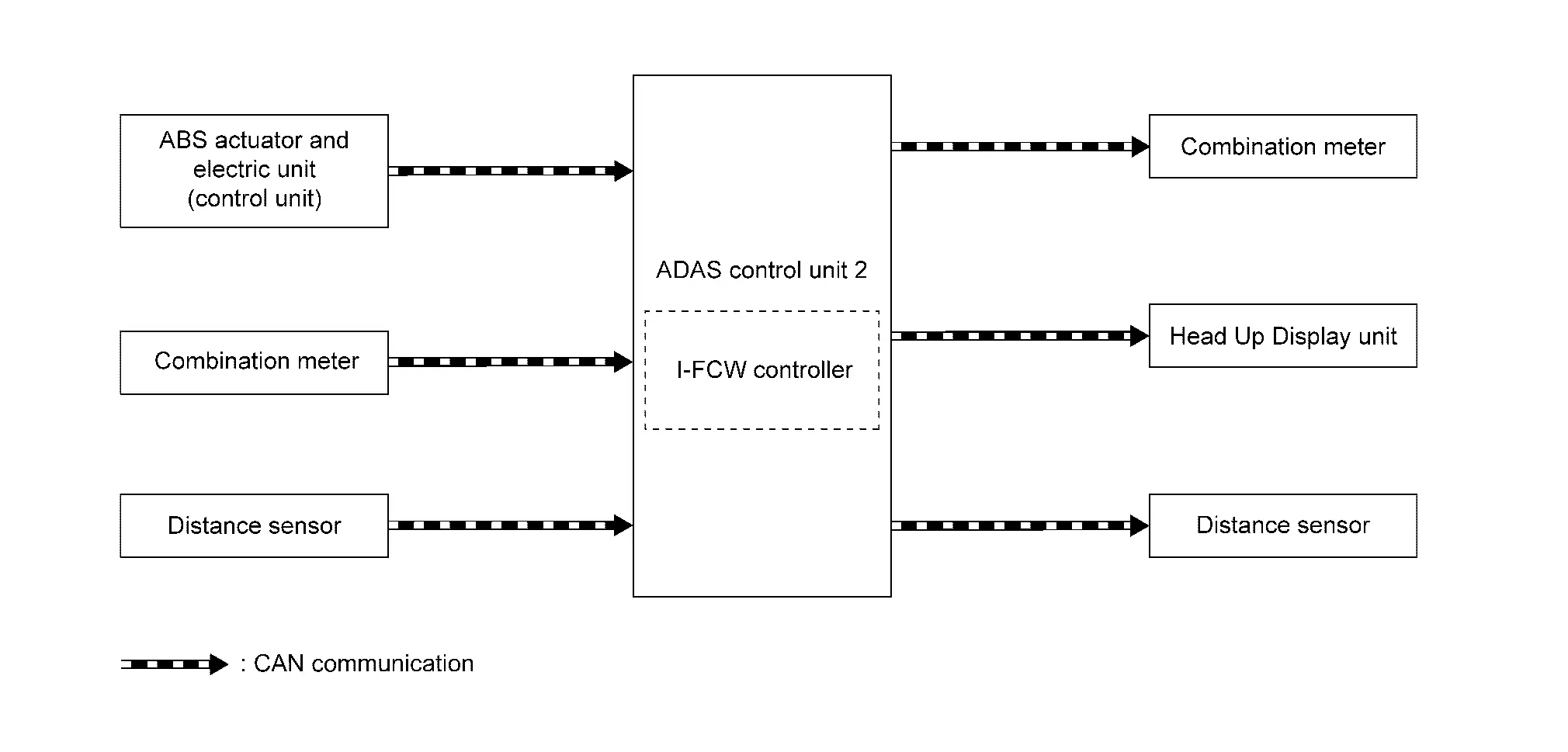
| Component | Description |
|---|---|
| ABS actuator and electric unit (control unit) | ABS Actuator and Electric Unit (Control Unit) |
| Combination meter (FULL TFT METER) | Combination Meter |
| Combination meter (7 INCH INFORMATION DISPLAY) | Combination Meter |
| Distance sensor | Distance Sensor |
| Head Up Display unit | Head Up Display Unit |
| ADAS control unit 2 | ADAS Control Unit 2 |
ADAS CONTROL UNIT 2 INPUT/OUTPUT SIGNAL ITEM
Input Signal Item
| Transmit unit | Signal name | Description | |
|---|---|---|---|
| ABS actuator and electric unit (control unit) | CAN communication | Nissan Ariya Vehicle speed signal (ABS) | Receives wheel speeds of four wheels |
| Combination meter | CAN communication | System selection signal | Receives a selection state of each item in “Driving Assistance” selected with Nissan Ariya vehicle information display |
| Distance sensor | CAN communication | Distance sensor signal | Receives detection results, such as the presence or absence of a leading Nissan Ariya vehicle and distance from the vehicle |
Output Signal Item
| Reception unit | Signal name | Description | |
|---|---|---|---|
| Combination meter | CAN communication | Meter display signal | Transmits a signal to display a state of the system on the information display |
| Buzzer output signal | Transmits a signal to activate buzzer | ||
| Distance sensor | CAN communication | Nissan Ariya Vehicle speed signal | Transmits a vehicle speed calculated by the ADAS control unit 2 |
| Head Up Display unit | CAN communication | Display signal | Transmits a signal to display a state of the system on the Head Up Display unit |
FUNCTION DESCRIPTION
-
The Intelligent Forward Collision Warning (I-FCW) system will function when the vehicle is driven at speeds of approximately 3 MPH (5 km/h) and above.
-
The Intelligent Forward Collision Warning (I-FCW) system alerts the driver by the Nissan Ariya vehicle ahead detection indicator and chime when the distance between own vehicle and a vehicle in front of the Nissan Ariya vehicle ahead becomes closer.
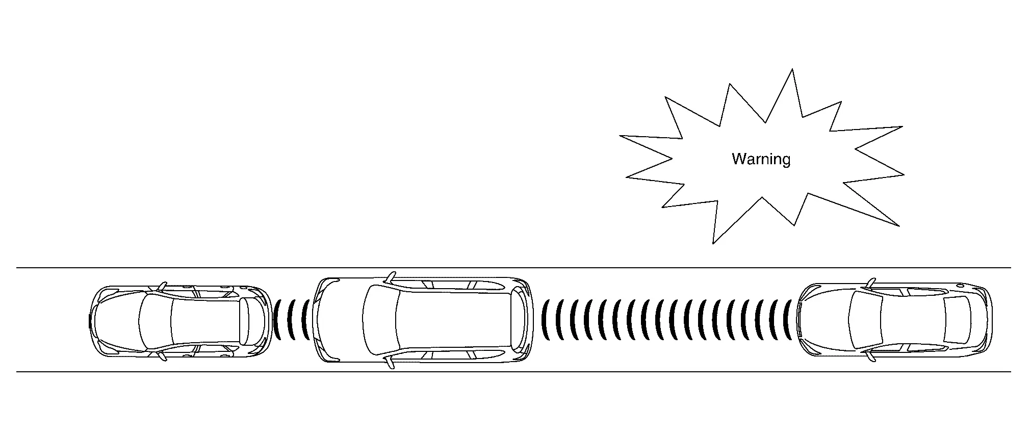
OPERATION DESCRIPTION
The distance from the vehicle in front of the vehicle ahead and a relative speed are calculated by using the distance sensor and an distance sensor signal is transmitted to the ADAS control unit 2 via CAN communication. When judging the necessity of warning according to the received distance sensor signal, the ADAS control unit 2 transmits a meter display signal and a buzzer output signal to the combination meter via CAN communication.
OPERATION CONDITION
ADAS control unit 2 performs the control when the following conditions are satisfied.
-
I-FCW system: ON
-
Vehicle speed: Approximately 5 km/h (3 MPH) and above.
-
Nissan Ariya Vehicle in front of the vehicle ahead: Detected.
 NOTE:
NOTE:
-
ON/OFF of I-FCW system is performed with the information display.
CANCEL CONDITION
The ADAS control unit 2 cancels the operation when the system is under any conditions of the operation cancellation condition.
-
When the system malfunction occurs.
-
When the distance sensor picks up interference from another radar source and making it impossible to detect a Nissan Ariya vehicle ahead.
-
When the distance sensor area of the front grill is dirty and the measurement of the distance between the Nissan Ariya vehicles becomes difficult.
Ldw
System Description
WITHOUT ProPILOT ASSIST 2.1
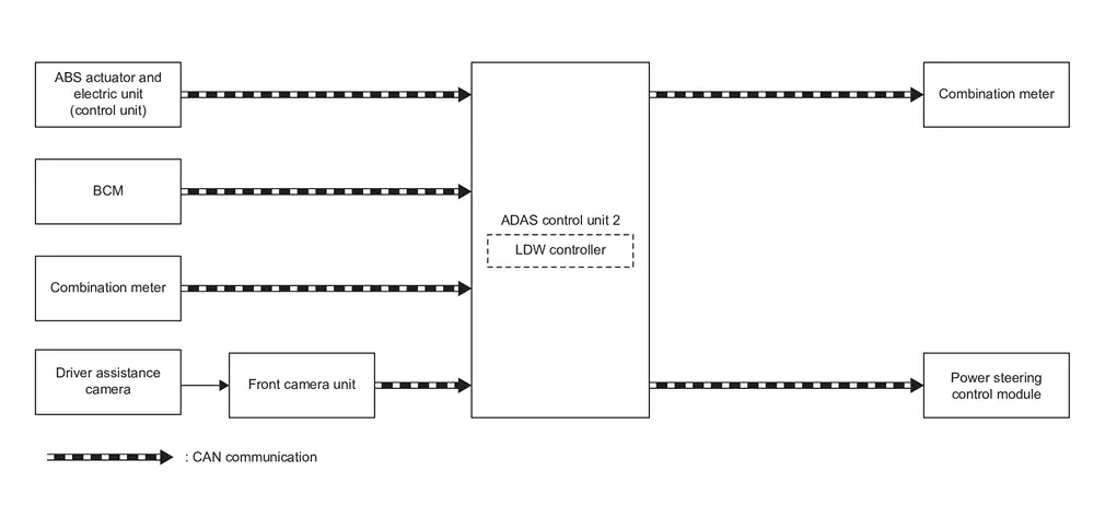
SYSTEM DIAGRAM
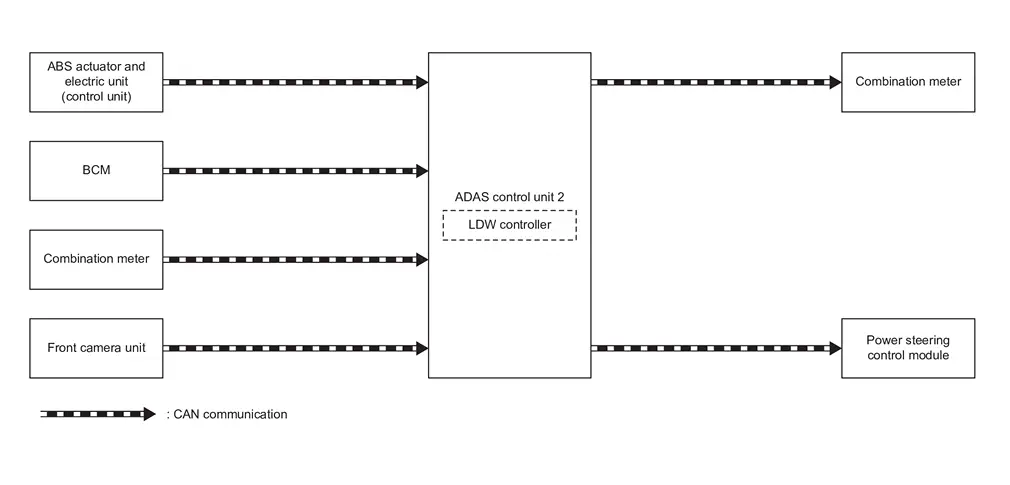
| Component | Description |
|---|---|
| ABS actuator and electric unit (control unit) | ABS Actuator and Electric Unit (Control Unit) |
| BCM | System Description |
| Front camera unit | Front Camera Unit |
| ADAS control unit 2 | ADAS Control Unit 2 |
| Combination meter (FULL TFT METER) | Combination Meter |
| Combination meter (7 INCH INFORMATION DISPLAY) | Combination Meter |
| Power steering control module | STEERING GEAR ASSEMBLY |
ADAS CONTROL UNIT 2 INPUT/OUTPUT SIGNAL ITEM
Input Signal Item
| Transmit unit | Signal name | Description | |
|---|---|---|---|
| ABS actuator and electric unit (control unit) | CAN communication | Nissan Ariya Vehicle speed signal (ABS) | Receives wheel speeds of four wheels |
| BCM | CAN communication | Turn indicator signal | Receives an operational state of the turn signal lamp and the hazard lamp |
| Combination meter | CAN communication | System selection signal | Receives a selection state of each item selected with the information display |
| Front camera unit | CAN communication | Detected lane condition signal | Receives detection results of lane marker |
Output Signal Item
| Reception unit | Signal name | Description | |
|---|---|---|---|
| Combination meter | CAN communication | Meter display signal | Transmits a meter display signal to turn ON the LDW system display |
| Power steering control module | CAN communication | Steering vibration signal | Transmits a steering vibration signal to activate ON the steering vibration |
FUNCTION DESCRIPTION
-
Lane Departure Warning (LDW) system provides a LDW function when the vehicle is driven at speeds of approximately 37 MPH (60 km/h) or more.
-
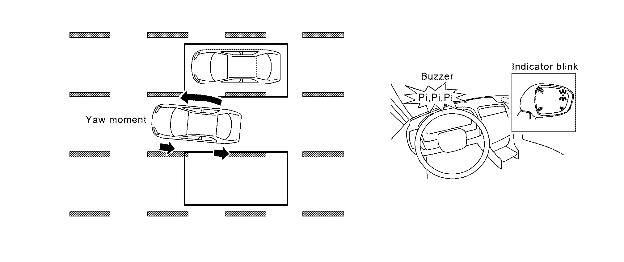
When the Nissan Ariya vehicle approaches either the left or the right side of the traveling lane, a steering vibration activates and the LDW indicator (yellow) on the combination meter blinks to alert the driver.
-
The warning does not occur during turn signal operation (Lane change side).
-
The warning function stops when the Nissan Ariya vehicle returns inside of the lane markers.
EXAMPLE
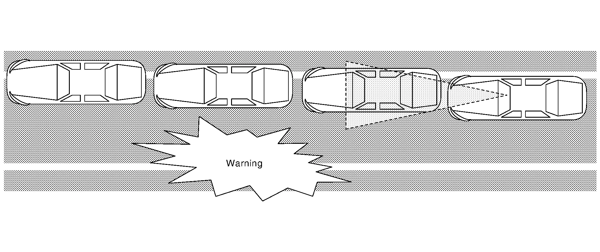
When the vehicle approaches the right lane marker, the driver is alerted by the steering vibration and the blinking of LDW warning display (yellow).
OPERATION DESCRIPTION
-
The front camera unit monitors lane markers of the traveling lane.
-
When judging from a lane marker detection signal that the Nissan Ariya vehicle is approaching the lane marker, the ADAS control unit 2 controls the following item to alert the driver.
-
ADAS control unit 2 transmits a steering vibration signal to power steering control module via CAN communication and activates the steering vibration.
-
ADAS control unit 2 transmits a meter display signal to combination meter via CAN communication and turns ON/OFF the LDW system display.
-
OPERATION CONDITION
ADAS control unit 2 performs the control when the following conditions are satisfied.
-
LDW system: ON
-
The intensity of the steering vibration can be changed on the information display.
-
Nissan Ariya Vehicle speed: approximately 60 km/h (37 MPH) or more
-
Turn indicator signal: After 2 seconds or more from turned OFF
NOTE:
-
LDW system ON/OFF can be set on the information display.
-
After the operating conditions of warning are satisfied, the warning continues until the Nissan Ariya vehicle speed reaches approximately 55 km/h (34 MPH)
-
The LDW system may not function properly, depending on the situation. Refer to Handling Precaution.
CANCEL CONDITION
The ADAS control unit 2 cancels the operation when the system is under any conditions of the operation cancellation condition.
-
When the system malfunction occurs.
-
When the front camera unit becomes high temperature [over approximately 40 °C (104 °F)].
WITH ProPILOT ASSIST 2.1
SYSTEM DIAGRAM
| Component | Description |
|---|---|
| ABS actuator and electric unit (control unit) | ABS Actuator and Electric Unit (Control Unit) |
| BCM | System Description |
| Front camera unit | Front Camera Unit |
| ADAS control unit 2 | ADAS Control Unit 2 |
| Combination meter (FULL TFT METER) | Combination Meter |
| Combination meter (7 INCH INFORMATION DISPLAY) | Combination Meter |
| Power steering control module | STEERING GEAR ASSEMBLY |
| Driver assistance camera | System Description |
ADAS CONTROL UNIT 2 INPUT/OUTPUT SIGNAL ITEM
Input Signal Item
| Transmit unit | Signal name | Description | |
|---|---|---|---|
| ABS actuator and electric unit (control unit) | CAN communication | Nissan Ariya Vehicle speed signal (ABS) | Receives wheel speeds of four wheels |
| BCM | CAN communication | Turn indicator signal | Receives an operational state of the turn signal lamp and the hazard lamp |
| Combination meter | CAN communication | System selection signal | Receives a selection state of each item selected with the information display |
| Front camera unit | CAN communication | Detected lane condition signal | Receives detection results of lane marker |
Output Signal Item
| Reception unit | Signal name | Description | |
|---|---|---|---|
| Combination meter | CAN communication | Meter display signal | Transmits a meter display signal to turn ON the LDW system display |
| Power steering control module | CAN communication | Steering vibration signal | Transmits a steering vibration signal to activate ON the steering vibration |
FUNCTION DESCRIPTION
-
Lane Departure Warning (LDW) system provides a LDW function when the vehicle is driven at speeds of approximately 60 km/h (37 MPH) or more.
-
When the Nissan Ariya vehicle approaches either the left or the right side of the traveling lane, a steering vibration activates and the LDW indicator (yellow) on the combination meter blinks to alert the driver.
-
The warning does not occur during turn signal operation (Lane change side).
-
The warning function stops when the Nissan Ariya vehicle returns inside of the lane markers.
EXAMPLE
When the vehicle approaches the right lane marker, the driver is alerted by the steering vibration and the blinking of LDW warning display (yellow).
OPERATION DESCRIPTION
-
The front camera unit monitors lane markers of the traveling lane.
-
When judging from a lane marker detection signal that the Nissan Ariya vehicle is approaching the lane marker, the ADAS control unit 2 controls the following item to alert the driver.
-
ADAS control unit 2 transmits a steering vibration signal to power steering control module via CAN communication and activates the steering vibration.
-
ADAS control unit 2 transmits a meter display signal to combination meter via CAN communication and turns ON/OFF the LDW system display.
-
OPERATION CONDITION
ADAS control unit 2 performs the control when the following conditions are satisfied.
-
LDW system: ON
-
Vehicle speed: approximately 60 km/h (37 MPH) or more
-
Turn indicator signal: After 2 seconds or more from turned OFF
NOTE:
-
LDW system ON/OFF can be set on the information display.
-
The intensity of the steering vibration can be changed on the information display.
-
After the operating conditions of warning are satisfied, the warning continues until the Nissan Ariya vehicle speed reaches approximately 55 km/h (34 MPH)
-
The LDW system may not function properly, depending on the situation. Refer to Handling Precaution.
CANCEL CONDITION
The ADAS control unit 2 cancels the operation when the system is under any conditions of the operation cancellation condition.
-
When the system malfunction occurs.
-
When the front camera unit becomes high temperature [over approximately 40 °C (104 °F)].
I-Li
System Description
WITHOUT ProPILOT ASSIST 2.1
SYSTEM DIAGRAM
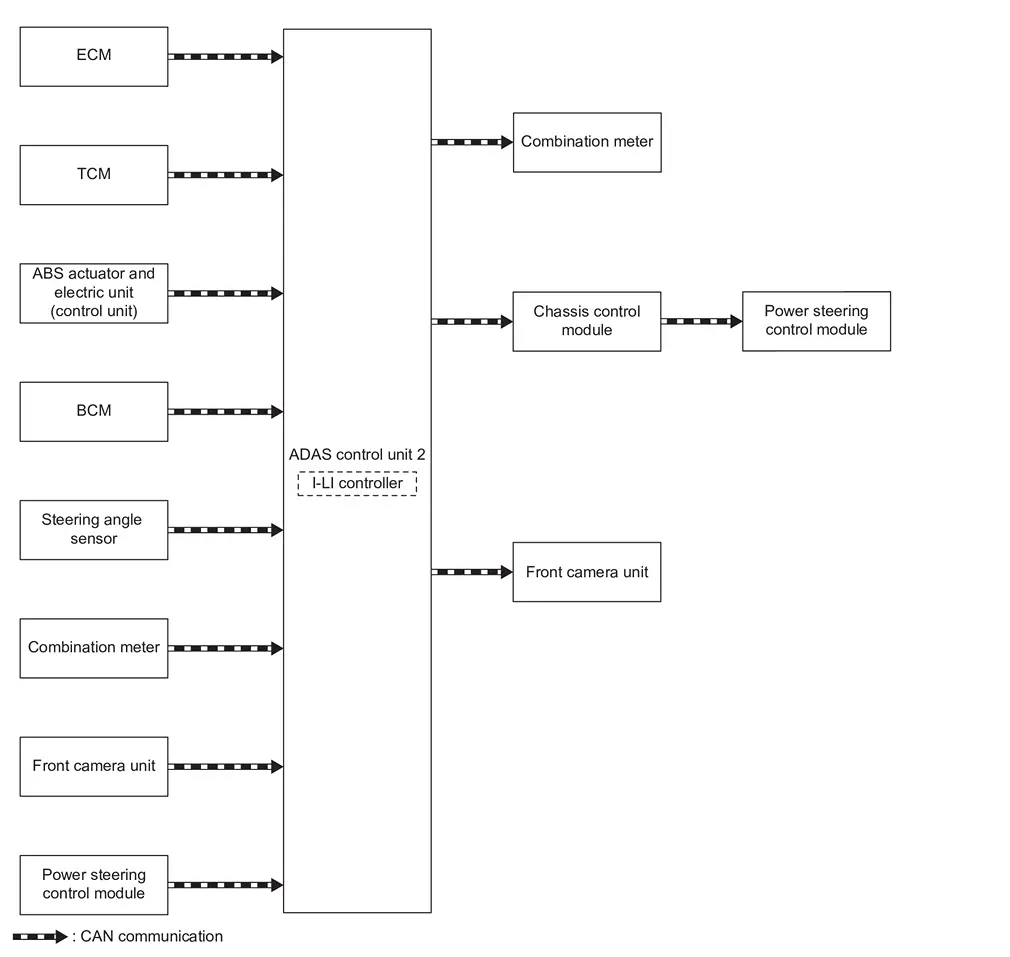
| Component | Description |
|---|---|
| ECM | ECM |
| TCM | TCM |
| BCM | System Description |
| Steering angle sensor | Steering Angle Sensor |
| Front camera unit | Front Camera Unit |
| ADAS control unit 2 | ADAS Control Unit 2 |
| Combination meter (FULL TFT METER) | Combination Meter |
| Combination meter (7 INCH INFORMATION DISPLAY) | Combination Meter |
| Power steering control module | STEERING GEAR ASSEMBLY |
| Chassis control module | Chassis Control Module |
ADAS CONTROL UNIT 2 INPUT/OUTPUT SIGNAL ITEM
Input Signal Item
| Transmit unit | Signal name | Description | |
|---|---|---|---|
| ECM | CAN communication | Accelerator pedal position signal | Receives accelerator pedal position (angle) |
| Engine speed signal | Receives engine speed | ||
| TCM | CAN communication | Input speed signal | Receives the number of revolutions of input shaft |
| Current gear position signal | Receives a current gear position | ||
| Shift position signal | Receives a select lever position | ||
| Output shaft revolution signal | Receives the number of revolutions of output shaft | ||
| Combination meter | CAN communication | System selection signal | Receives a selection state of each item in “Driving Aids” selected with the information display |
| BCM | CAN communication | Turn indicator signal | Receives an operational state of the turn signal lamp and the hazard lamp |
| Steering angle sensor | CAN communication | Steering angle sensor malfunction signal | Receives a malfunction state of steering angle sensor |
| Steering angle speed signal | Receives the turning angle speed of the steering wheel | ||
| Power steering control module | CAN communication | Steering torque signal | Receive steering input torque |
| Steering angle signal | Receive the number of revolutions, turning direction of the steering wheel | ||
| Front camera unit | CAN communication | Detected lane condition signal | Receives detection results of lane marker |
Output Signal Item
| Reception unit | Signal name | Description | |
|---|---|---|---|
| Power steering control module (via chassis control module) | CAN communication | I-LI (LDP) operation signal | Transmits an I-LI (LDP) operation signal necessary for I-LI (LDP) |
| Combination meter | CAN communication | Meter display signal | Transmits an meter display signal to turn ON the I-LI system display |
| Front camera unit | CAN communication | Nissan Ariya Vehicle speed signal | Transmits a vehicle speed calculated by ADAS control unit 2 |
| Turn indicator signal | Transmits a turn indicator signal received from BCM | ||
| Steering vibration motor | Motor operation signal | Activates a motor operation signal to active the steering vibration motor | |
FUNCTION DESCRIPTION
-
Intelligent-Lane Intervention (I-LI) system provides a lane departure warning and steering control assistance when the Nissan Ariya vehicle is driven at speeds of approximately 37 MPH (60 km/h) or more.
-
When the vehicle approaches either the left or the right side of the traveling lane, a steering vibration activates and the I-LI warning display on the information display blinks to alert the driver. Then, the ILI system automatically The system helps assist the driver to return the Nissan Ariya vehicle to the center of the traveling lane by applying the steering to the left or right (for a short period of time) for a short period of time to help assist the driver to return the Nissan Ariya vehicle to the center of the traveling lane.
-
Warning and steering control are not performed during turn signal operation (lane change side).
-
The warning and assist functions stop when the Nissan Ariya vehicle returns to a position inside of the lane marker.
EXAMPLE
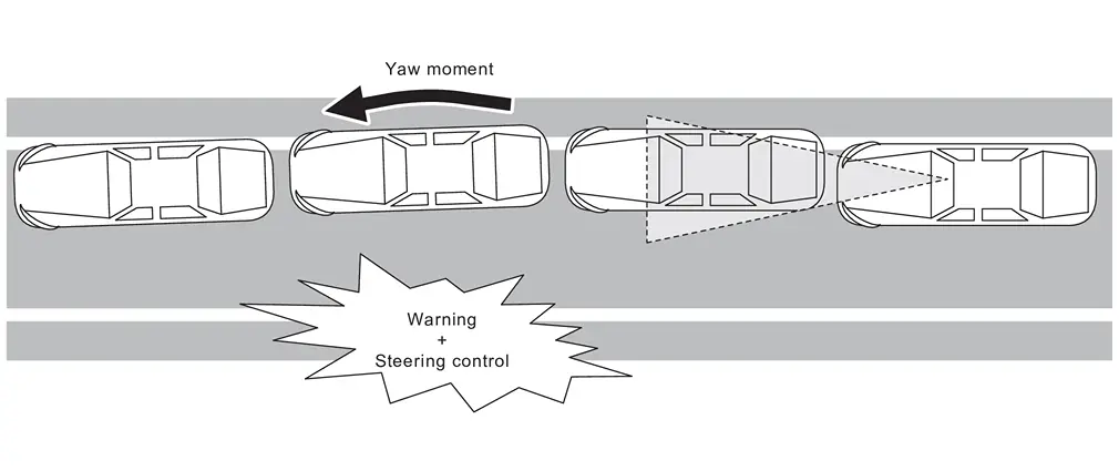
When the vehicle approaches the right lane marker or road edge , the driver is alerted by the steering vibration and the blinking of I-LI indicator. Simultaneously, the left steering is controlled independently to generate force toward the direction to recover the Nissan Ariya vehicle from the lane departure.
OPERATION DESCRIPTION
-
When the system is turned ON by ProPILOT assist switch, ADAS control unit 2 transmits meter display signal to combination meter via CAN communication.
-
Front camera unit monitors lane markers of the traveling lane. It transmits the detected lane condition signal to ADAS control unit 2 via chassis CAN communication.
-
When judging from a lane marker detection signal that the Nissan Ariya vehicle is approaching the lane marker, ADAS control unit 2 controls the following items.
-
Activates the steering vibration motor by ADAS control unit 2.
-
Transmits a meter display signal to combination meter via CAN communication.
-
Calculates necessary steering wheel angle to transmit I-LI operation signals to the power steering control module via CAN communication.
-
-
When receiving the I-LI operation signals, power steering control module controls steering wheel angle.
-
When receiving the signal from ADAS control unit 2, combination meter turns ON/OFF the I-LI system display.
OPERATION CONDITION
ADAS control unit 2 performs the control when the following conditions are satisfied.
-
I-LI system: ON
-
Vehicle speed: approximately 60 km/h (37 MPH) or more
-
Turn indicator signal: After 2 seconds or more from turned OFF
NOTE:
-
I-LI system ON/OFF can be set on the information display.
-
After the operating conditions are satisfied, the control continues until the Nissan Ariya vehicle speed reaches approximately 50 km/h (31 MPH).
-
The I-LI system may not function properly, depending on the situation.
CANCEL CONDITION
The ADAS control unit 2 cancels the operation when the system is under any conditions of the operation cancellation condition.
-
When the system malfunction occurs.
-
When the VDC or ABS (Including the TCS) operates.
-
When the VDC is turned OFF
-
When the SNOW mode and the OFF-ROAD mode is selected (AWD models).
-
When the front camera unit becomes high temperature [over approximately 40 °C (104 °F)].
WITH ProPILOT ASSIST 2.1
SYSTEM DIAGRAM
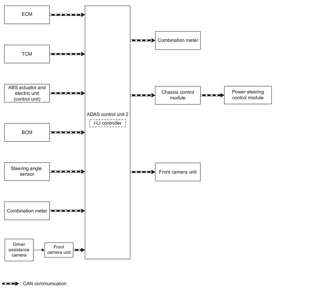
| Component | Description |
|---|---|
| ECM | ECM |
| TCM | TCM |
| BCM | System Description |
| Steering angle sensor | Steering Angle Sensor |
| Front camera unit | Front Camera Unit |
| ADAS control unit 2 | ADAS Control Unit 2 |
| Combination meter (FULL TFT METER) | Combination Meter |
| Combination meter (7 INCH INFORMATION DISPLAY) | Combination Meter |
| Power steering control module | STEERING GEAR ASSEMBLY |
| Chassis control module | Chassis Control Module |
| Driver assistance camera | System Description |
ADAS CONTROL UNIT 2 INPUT/OUTPUT SIGNAL ITEM
Input Signal Item
| Transmit unit | Signal name | Description | |
|---|---|---|---|
| ECM | CAN communication | Accelerator pedal position signal | Receives accelerator pedal position (angle) |
| Engine speed signal | Receives engine speed | ||
| TCM | CAN communication | Input speed signal | Receives the number of revolutions of input shaft |
| Current gear position signal | Receives a current gear position | ||
| Shift position signal | Receives a select lever position | ||
| Output shaft revolution signal | Receives the number of revolutions of output shaft | ||
| Combination meter | CAN communication | System selection signal | Receives a selection state of each item in “Driving Aids” selected with the information display |
| BCM | CAN communication | Turn indicator signal | Receives an operational state of the turn signal lamp and the hazard lamp |
| Steering angle sensor | CAN communication | Steering angle sensor malfunction signal | Receives a malfunction state of steering angle sensor |
| Steering angle speed signal | Receives the turning angle speed of the steering wheel | ||
| Power steering control module | CAN communication | Steering torque signal | Receive steering input torque |
| Steering angle signal | Receive the number of revolutions, turning direction of the steering wheel | ||
| Front camera unit | CAN communication | Detected lane condition signal | Receives detection results of lane marker |
Output Signal Item
| Reception unit | Signal name | Description | |
|---|---|---|---|
| Power steering control module (via chassis control module) | CAN communication | I-LI (LDP) operation signal | Transmits an I-LI (LDP) operation signal necessary for I-LI (LDP) |
| Combination meter | CAN communication | Meter display signal | Transmits an meter display signal to turn ON the I-LI system display |
| Front camera unit | CAN communication | Nissan Ariya Vehicle speed signal | Transmits a vehicle speed calculated by ADAS control unit 2 |
| Turn indicator signal | Transmits a turn indicator signal received from BCM | ||
| Steering vibration motor | Motor operation signal | Activates a motor operation signal to active the steering vibration motor | |
FUNCTION DESCRIPTION
-
Intelligent-Lane Intervention (I-LI) system provides a lane departure warning and steering control assistance when the Nissan Ariya vehicle is driven at speeds of approximately 60 km/h (37 MPH) or more.
-
When the vehicle approaches either the left or the right side of the traveling lane, a steering vibration activates and the I-LI warning display on the information display blinks to alert the driver. Then, the ILI system automatically the system helps assist the driver to return the Nissan Ariya vehicle to the center of the traveling lane by applying the steering to the left or right (for a short period of time) for a short period of time to help assist the driver to return the Nissan Ariya vehicle to the center of the traveling lane.
-
Warning and steering control are not performed during turn signal operation (lane change side).
-
The warning and assist functions stop when the Nissan Ariya vehicle returns to a position inside of the lane marker.
EXAMPLE
When the vehicle approaches the right lane marker or road edge, the driver is alerted by the steering vibration and the blinking of I-LI indicator. Simultaneously, the left steering is controlled independently to generate force toward the direction to recover the Nissan Ariya vehicle from the lane departure.
OPERATION DESCRIPTION
-
When the system is turned ON by ProPILOT assist switch, ADAS control unit 2 transmits meter display signal to combination meter via CAN communication.
-
The front camera unit measures the lane marker using a driver assistance camera and transmits the detected lane condition signal to the ADAS control unit 2.
-
When judging from a lane marker detection signal that the Nissan Ariya vehicle is approaching the lane marker, ADAS control unit 2 controls the following items.
-
Activates the steering vibration motor by ADAS control unit 2.
-
Transmits a meter display signal to combination meter via CAN communication.
-
Calculates necessary steering wheel angle to transmit I-LI operation signals to the power steering control module via CAN communication.
-
-
Calculates necessary steering wheel angle to transmit I-LI operation signals to the power steering control module via CAN communication.
-
When receiving the signal from ADAS control unit 2, combination meter turns ON/OFF the I-LI system display.
OPERATION CONDITION
ADAS control unit 2 performs the control when the following conditions are satisfied.
-
I-LI system: ON
-
Vehicle speed: approximately 60 km/h (37 MPH) or more
-
Turn indicator signal: After 2 seconds or more from turned OFF
NOTE:
-
I-LI system ON/OFF can be set on the information display.
-
After the operating conditions are satisfied, the control continues until the Nissan Ariya vehicle speed reaches approximately 50 km/h (31 MPH).
-
The I-LI system may not function properly, depending on the situation.
CANCEL CONDITION
The ADAS control unit 2 cancels the operation when the system is under any conditions of the operation cancellation condition.
-
When the system malfunction occurs.
-
When the VDC or ABS (Including the TCS) operates.
-
When the VDC is turned OFF
-
When the SNOW mode and the OFF-ROAD mode is selected (AWD models).
-
When the front camera unit becomes high temperature [over approximately 40 °C (104 °F)].
Bsw
System Description
SYSTEM DIAGRAM
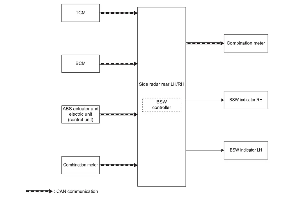
| Component | Description |
|---|---|
| TCM | TCM |
| BCM | System Description |
| ABS actuator and electric unit (control unit) | ABS Actuator and Electric Unit (Control Unit) |
| Combination meter (FULL TFT METER) | Combination Meter |
| Combination meter (7 INCH INFORMATION DISPLAY) | Combination Meter |
| Side radar rear LH/RH | Side Radar LH/RH |
| BSW indicator LH, RH | BSW Indicator LH/RH |
SIDE RADAR INPUT/OUTPUT SIGNAL ITEM
Input Signal Item
| Transmit unit | Signal name | Description | |
|---|---|---|---|
| TCM | CAN communication | Shift position signal | Receives a select lever position |
| ABS actuator and electric unit (control unit) | CAN communication | Nissan Ariya Vehicle speed signal (ABS) | Receives wheel speeds of four wheels |
| BCM | CAN communication | Turn indicator signal | Receives an operational state of the turn signal lamp and the hazard lamp |
| Dimmer signal | Receives ON/OFF state of dimmer signal | ||
| Combination meter | CAN communication | System selection signal | Receives a selection state of each item selected with the information display |
Output Signal Item
| Reception unit | Signal name | Description | |
|---|---|---|---|
| Combination meter | CAN communication | Meter display signal | Transmits a signal to display a state of the system on the information display |
| Buzzer output signal | Transmits a signal to activate buzzer | ||
| BSW indicator LH, RH | BSW indicator signal | Transmits a BSW indicator signal to turn ON the BSW indicator | |
| BSW indicator dimmer signal | Transmits a BSW indicator dimmer signal to dimmer BSW indicator | ||
FUNCTION DESCRIPTION
-
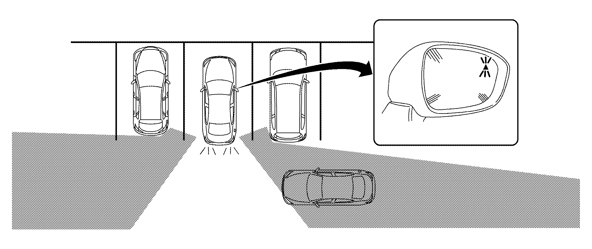
The Blind Spot Warning (BSW) system can help alert the driver of other vehicles in adjacent lanes when changing lanes.
-
The BSW system uses side radar installed near the rear bumper to detect Nissan Ariya vehicles in an adjacent lane.
-
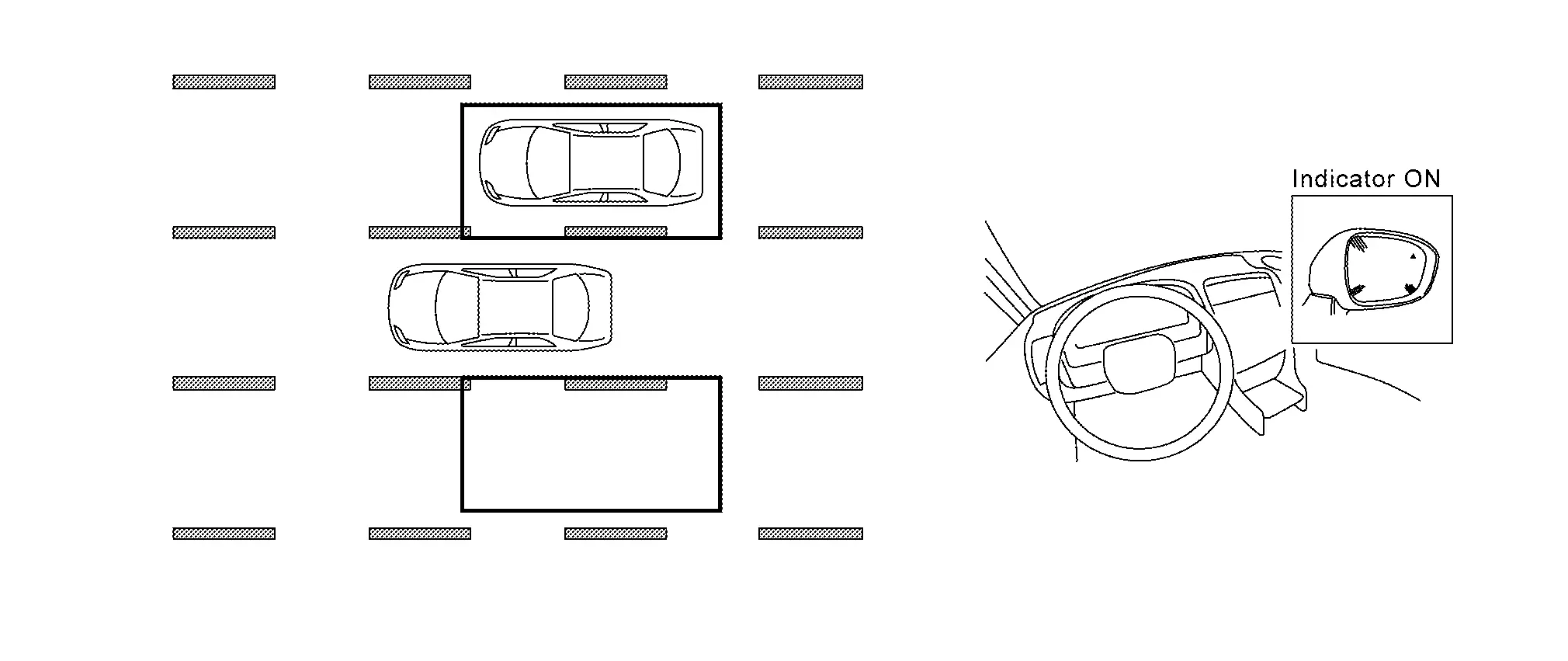
The side radar can detect vehicles on either side of vehicle within the detection zone shown as illustrated.
-
This detection zone starts from the outside mirror of Nissan Ariya vehicle and extends approximately 10 ft (3.0 m) behind the rear bumper, and approximately 10 ft (3.0 m) sideways.
-
The BSW system operates above approximately 20 MPH (32 km/h).
-
If the side radar detects Nissan Ariya vehicles in the detection zone, the BSW indicator illuminates.
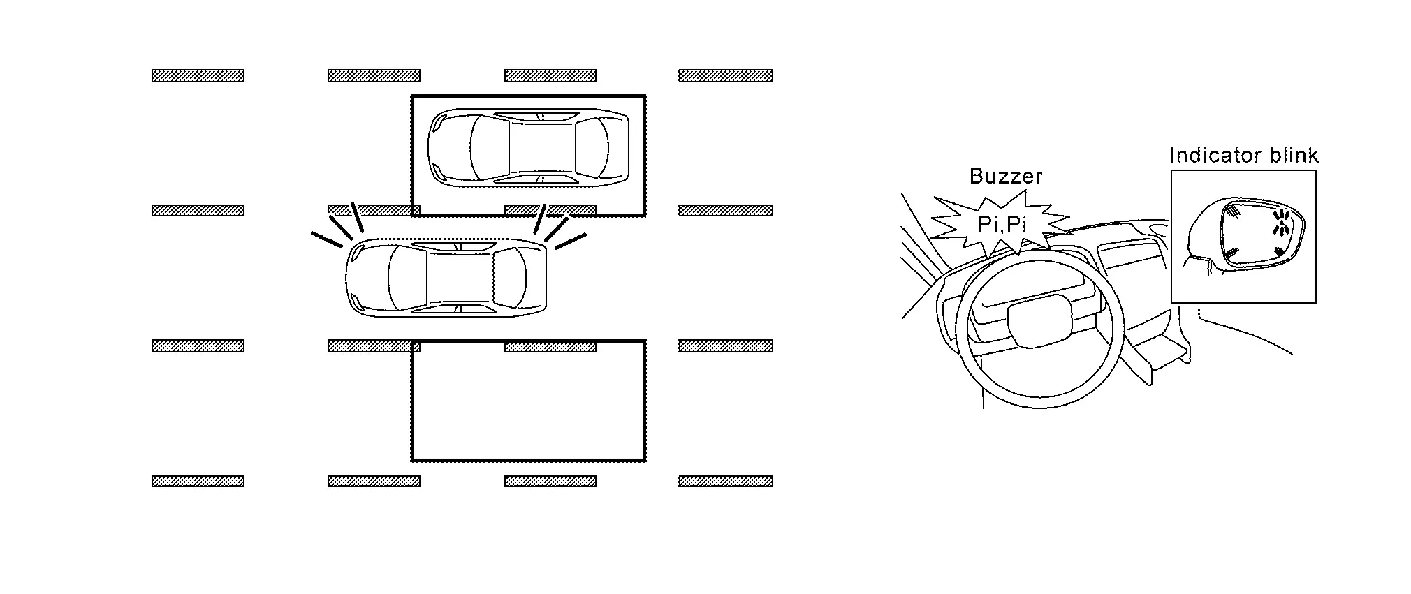
-
If the driver then activates the turn signal, a buzzer sounds twice and the BSW indicator blinks.
NOTE:
A buzzer sounds if the side radar have already detected Nissan Ariya vehicles when the driver activates the turn signal. If a vehicle comes into the detection zone after the driver activates the turn signal, then only the BSW indicator blinks and no buzzer sounds.
OPERATION DESCRIPTION
-
Side radar enables BSW system.
-
The side radar turns on the BSW system when the turned ON by information display.
-
Side radar detects a Nissan Ariya vehicle in the adjacent lane.
-
Side radar starts the control as follows, based on a vehicle detection signal, turn signal and dimmer signal transmitted from BCM via CAN communication:
-
Transmits BSW indicator signal and BSW indicator dimmer signal to BSW indicator.
-
Transmits a buzzer output signal to combination meter.
-
OPERATION CONDITION
Side radar performs the control when the following conditions are satisfied.
-
BSW system: ON
-
Vehicle speed: Approximately 32 km/h (20 MPH) or more
NOTE:
-
ON/OFF of BSW system is performed with the information display.
-
After the operating conditions of warning are satisfied, the warning continues until the Nissan Ariya vehicle speed reaches approximately 29 km/h (18 MPH)
-
The BSW system may not function properly, depending on the situation. Refer to Handling Precaution.
CANCEL CONDITION
The side radar cancels the operation when the system is under any conditions of the operation cancellation condition.
-
When the system malfunction occurs.
-
When the area around the side radar is dirty.
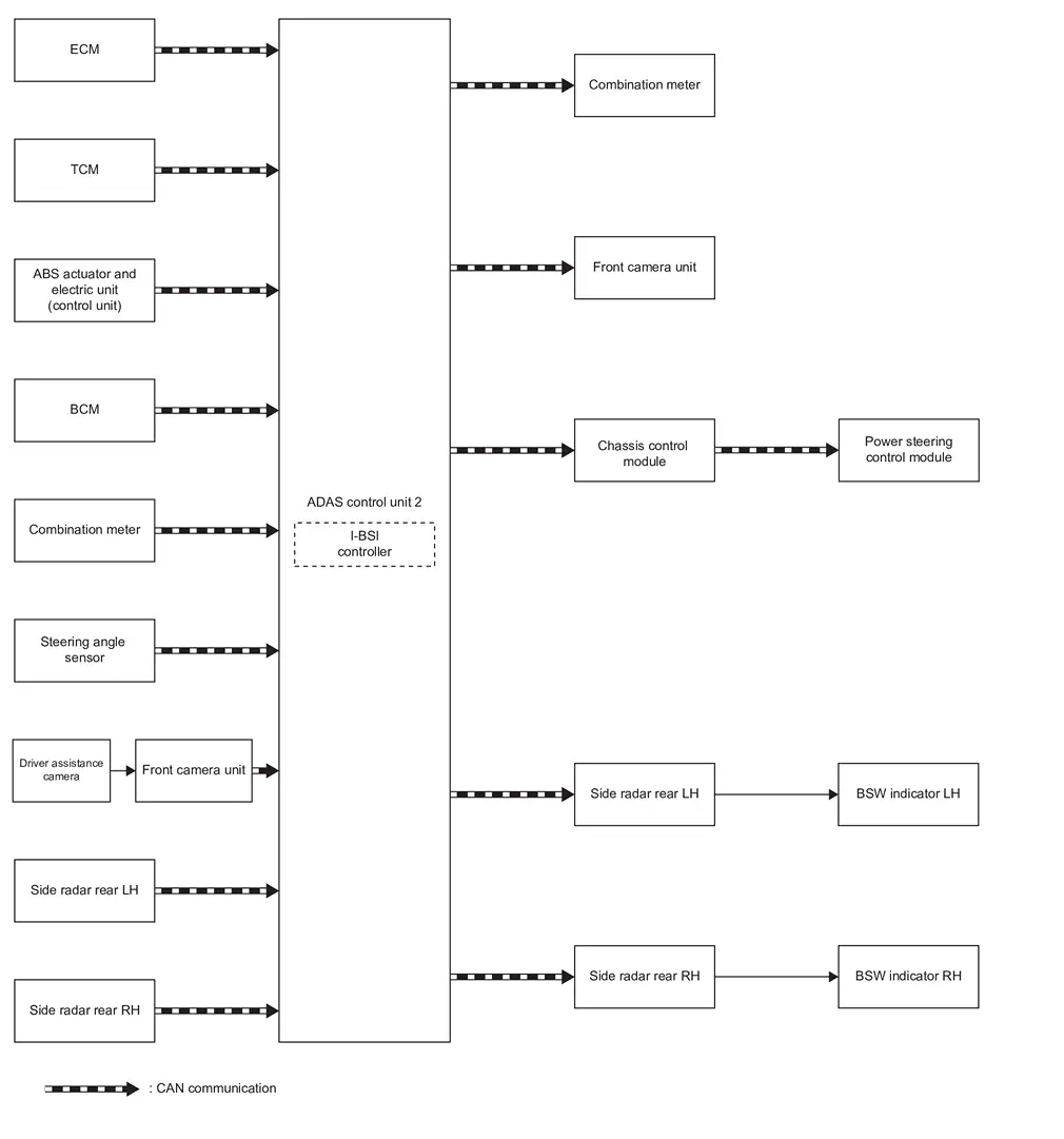
I-Bsi
System Description
WITHOUT ProPILOT ASSIST 2.1
SYSTEM DIAGRAM
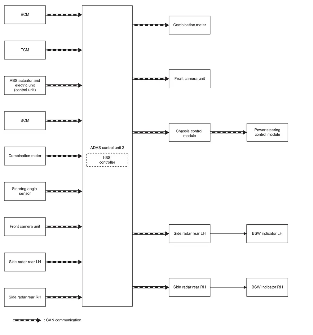
| Component | Description |
|---|---|
| ECM | ECM |
| TCM | TCM |
| Power steering control module | STEERING GEAR ASSEMBLY |
| BCM | System Description |
| Combination meter (FULL TFT METER) | Combination Meter |
| Combination meter (7 INCH INFORMATION DISPLAY) | Combination Meter |
| Steering angle sensor | Steering Angle Sensor |
| ADAS control unit 2 | ADAS Control Unit 2 |
| Side radar rear LH/RH | Side Radar LH/RH |
| Front camera unit | Front camera unit |
| BSW indicator LH, RH | BSW Indicator LH/RH |
| Chassis control module | Chassis Control Module |
ADAS CONTROL UNIT 2 INPUT/OUTPUT SIGNAL ITEM
Input Signal Item
| Transmit unit | Signal name | Description | |
|---|---|---|---|
| ECM | CAN communication | Accelerator pedal position signal | Receives accelerator pedal position (angle) |
| Engine speed signal | Receives engine speed | ||
| TCM | CAN communication | Input speed signal | Receives the number of revolutions of input shaft |
| Current gear position signal | Receives a current gear position | ||
| Shift position signal | Receives a select lever position | ||
| Output shaft revolution signal | Receives the number of revolutions of output shaft | ||
| BCM | CAN communication | Turn indicator signal | Receives an operational state of the turn signal lamp and the hazard lamp |
| Dimmer signal | Receives ON/OFF state of dimmer signal | ||
| Steering angle sensor | CAN communication | Steering angle sensor malfunction signal | Receives a malfunction state of steering angle sensor |
| Steering angle speed signal | Receives the turning angle speed of the steering wheel | ||
| Power steering control module | CAN communication | Steering torque signal | Receive steering input torque |
| Steering angle signal | Receive the number of revolutions, turning direction of the steering wheel | ||
| Combination meter | CAN communication | System selection signal | Receives a selection state of each item selected with the information display |
| Front camera unit | CAN communication | Detected lane condition signal | Receives detection results of lane marker |
| Side radar rear LH/RH | CAN communication | Nissan Ariya Vehicle detection signal | Receives vehicle detection condition of detection zone |
Output Signal Item
| Reception unit | Signal name | Description | |
|---|---|---|---|
| Power steering control module (via chassis control module) | CAN communication | I-BSI (BSI) operation signal | Transmits an I-BSI (BSI) operation signal necessary for I-BSI (BSI) |
| Combination meter | CAN communication | Meter display signal | Transmits a signal to display a state of the system on the information display |
| Buzzer output signal | Transmits a signal to activate buzzer | ||
| Side radar rear LH/RH | CAN communication | Nissan Ariya Vehicle speed signal | Transmits a vehicle speed calculated by the ADAS control unit 2 |
| BSW indicator signal | Transmits a BSW indicator signal to turn ON the BSW indicator | ||
| BSW indicator dimmer signal | Transmits a BSW indicator dimmer signal to dimmer BSW indicator | ||
| Front camera unit | CAN communication | Nissan Ariya Vehicle speed signal | Transmits a vehicle speed calculated by ADAS control unit 2 |
| Turn indicator signal | Transmits a turn indicator signal received from BCM | ||
FUNCTION DESCRIPTION
-
The I-BSI system can help alert the driver of other vehicles in adjacent lanes when changing lanes. I-BSI always operates together with Blind Spot Warning.
-
The I-BSI system operates above approximately 60 km/h (37 MPH).
-
The I-BSI system uses side radar installed near the rear bumper to detect other Nissan Ariya vehicles beside vehicle in an adjacent lane.
-
The side radar can detect vehicles on either side of Nissan Ariya vehicle within the detection zone shown as illustrated.
-
This detection zone starts from the outside mirror of Nissan Ariya vehicle and extends approximately 10 ft (3.0 m) behind the rear bumper, and approximately 10 ft (3.0 m) sideways.
-
If the BSW indicator is illuminated while Nissan Ariya vehicle is approaching a lane marker, the BSW indicator blinks and an audible warning will sound three times. Then the system helps assist the driver to return the Nissan Ariya vehicle to the center of the traveling lane by applying the steering to the left or right (for a short period of time) on one side of the Nissan Ariya vehicle for a short period of time to help return the vehicle back to the center of the lane.
-
I-BSI operates regardless of turn signal usage.
-
The brightness of BSW indicator lights is adjusted automatically depending on the brightness of the ambient light.
NOTE:
-
I-BSI is typically activated earlier than I-LI when getting closer to the lane marker.
-
Warning and steering control will only be activated if the BSW indicator is already illuminated when Nissan Ariya vehicle approaches a lane marker.
-
If another vehicle comes into the detection zone after vehicle has crossed a lane marker, no warning or steering control will be activated.
OPERATION DESCRIPTION
-
ADAS control unit 2 enables I-BSI system.
-
Turn ON the dynamic driver assistance switch, and I-BSI system setting on the information display.
-
Combination meter turns I-BSI system display ON/OFF according to the signals from ADAS control unit 2 via CAN communication.
-
Side radar detects a Nissan Ariya vehicle in the adjacent lane, and transmits the vehicle detection signal to ADAS control unit 2 via CAN communication.
-
Side radar receives Nissan Ariya vehicle speed signal from ADAS control unit 2 and changes its detecting function.
-
Front camera unit monitors lane markers of the traveling lane and transmits the detected lane condition signal to ADAS control unit 2 via CAN communication.
-
ADAS control unit 2 starts the control as follows, based on a Nissan Ariya vehicle detection signal, lane condition signal, turn signal and position light request signal transmitted from BCM via CAN communication:
-
BSW indicator signal and BSW indicator dimmer signal transmission to side radar.
-
Calculates necessary steering wheel angle to transmit LDP operation signals to the power steering control module via CAN communication.
-
-
Side radar transmits an indicator operation signal to the BSW indicator according to BSW indicator operation signal and BSW indicator dimmer signal.
-
When receiving the BSI operation signals, power steering control module controls steering wheel angle.
OPERATION CONDITION
-
I-BSI system: ON
-
Vehicle speed: Approximately 60 km/h (37 MPH) or more
NOTE:
-
I-BSI system ON/OFF can be set on the information display.
-
The I-BSI system may not function properly, depending on the situation. Refer to Handling Precaution.
-
I-BSI braking will not operate or will stop operating and only a warning chime will sound under the following conditions.
-
When the brake pedal is depressed.
-
When the accelerator pedal is depressed while steering control assist is provided.
-
When steering quickly.
-
When the ProPILOT Assist or AEB warnings sound.
-
When the hazard warning flashers are operated.
-
When driving on a curve at a high speed.
-
-
Under the following conditions, the I-BSI system will be turned off automatically, a beep will sound and the I-BSI system display will change color to yellow. The BSW system is still available, but the I-BSI system will not be available until the conditions no longer exist.
-
When the VDC system (except TCS function) or ABS operates.
-
When the VDC system is turned OFF.
-
CANCEL CONDITION
The ADAS control unit 2 cancels the operation when the system is under any conditions of the operation cancellation condition.
-
When the system malfunction occurs.
-
When the front camera unit becomes high temperature [over approximately 40 °C (104 °F)].
-
When the area around the side radar is dirty.
-
When the VDC or ABS (Including the TCS) operates.
-
When the VDC is turned OFF
-
When the SNOW mode and the OFF-ROAD mode is selected (AWD models).
WITH ProPILOT ASSIST 2.1
SYSTEM DIAGRAM
| Component | Description |
|---|---|
| ECM | ECM |
| TCM | TCM |
| Power steering control module | STEERING GEAR ASSEMBLY |
| BCM | System Description |
| Combination meter (FULL TFT METER) | Combination Meter |
| Combination meter (7 INCH INFORMATION DISPLAY) | Combination Meter |
| Steering angle sensor | Steering Angle Sensor |
| ADAS control unit 2 | ADAS Control Unit 2 |
| Side radar rear LH/RH | Side Radar LH/RH |
| Front camera unit | Front camera unit |
| BSW indicator LH, RH | BSW Indicator LH/RH |
| Chassis control module | Chassis Control Module |
| Driver assistance camera | System Description |
ADAS CONTROL UNIT 2 INPUT/OUTPUT SIGNAL ITEM
Input Signal Item
| Transmit unit | Signal name | Description | |
|---|---|---|---|
| ECM | CAN communication | Accelerator pedal position signal | Receives accelerator pedal position (angle) |
| Engine speed signal | Receives engine speed | ||
| TCM | CAN communication | Input speed signal | Receives the number of revolutions of input shaft |
| Current gear position signal | Receives a current gear position | ||
| Shift position signal | Receives a select lever position | ||
| Output shaft revolution signal | Receives the number of revolutions of output shaft | ||
| BCM | CAN communication | Turn indicator signal | Receives an operational state of the turn signal lamp and the hazard lamp |
| Dimmer signal | Receives ON/OFF state of dimmer signal | ||
| Steering angle sensor | CAN communication | Steering angle sensor malfunction signal | Receives a malfunction state of steering angle sensor |
| Steering angle speed signal | Receives the turning angle speed of the steering wheel | ||
| Power steering control module | CAN communication | Steering torque signal | Receive steering input torque |
| Steering angle signal | Receive the number of revolutions, turning direction of the steering wheel | ||
| Combination meter | CAN communication | System selection signal | Receives a selection state of each item selected with the information display |
| Front camera unit | CAN communication | Detected lane condition signal | Receives detection results of lane marker |
| Side radar rear LH/RH | CAN communication | Nissan Ariya Vehicle detection signal | Receives vehicle detection condition of detection zone |
Output Signal Item
| Reception unit | Signal name | Description | |
|---|---|---|---|
| Power steering control module (via chassis control module) | CAN communication | I-BSI (BSI) operation signal | Transmits an I-BSI (BSI) operation signal necessary for I-BSI (BSI) |
| Combination meter | CAN communication | Meter display signal | Transmits a signal to display a state of the system on the information display |
| Buzzer output signal | Transmits a signal to activate buzzer | ||
| Side radar rear LH/RH | CAN communication | Nissan Ariya Vehicle speed signal | Transmits a vehicle speed calculated by the ADAS control unit 2 |
| BSW indicator signal | Transmits a BSW indicator signal to turn ON the BSW indicator | ||
| BSW indicator dimmer signal | Transmits a BSW indicator dimmer signal to dimmer BSW indicator | ||
| Front camera unit | CAN communication | Nissan Ariya Vehicle speed signal | Transmits a vehicle speed calculated by ADAS control unit 2 |
| Turn indicator signal | Transmits a turn indicator signal received from BCM | ||
FUNCTION DESCRIPTION
-
The I-BSI system can help alert the driver of other vehicles in adjacent lanes when changing lanes. I-BSI always operates together with Blind Spot Warning.
-
The I-BSI system operates above approximately 60 km/h (37 MPH).
-
The I-BSI system uses side radar installed near the rear bumper to detect other Nissan Ariya vehicles beside vehicle in an adjacent lane.
-
The side radar can detect vehicles on either side of Nissan Ariya vehicle within the detection zone shown as illustrated.
-
This detection zone starts from the outside mirror of Nissan Ariya vehicle and extends approximately 10 ft (3.0 m) behind the rear bumper, and approximately 10 ft (3.0 m) sideways.
-
If the BSW indicator is illuminated while Nissan Ariya vehicle is approaching a lane marker, the BSW indicator blinks and an audible warning will sound three times. Then the system helps assist the driver to return the Nissan Ariya vehicle to the center of the traveling lane by applying the steering to the left or right (for a short period of time) on one side of the Nissan Ariya vehicle for a short period of time to help return the vehicle back to the center of the lane.
-
I-BSI operates regardless of turn signal usage.
-
The brightness of BSW indicator lights is adjusted automatically depending on the brightness of the ambient light.
NOTE:
-
I-BSI is typically activated earlier than I-LI when getting closer to the lane marker.
-
Warning and steering control will only be activated if the BSW indicator is already illuminated when Nissan Ariya vehicle approaches a lane marker.
-
If another vehicle comes into the detection zone after vehicle has crossed a lane marker, no warning or steering control will be activated.
OPERATION DESCRIPTION
-
ADAS control unit 2 enables I-BSI system.
-
Turn ON the ProPILOT assist switch, and I-BSI system setting on the information display.
-
Combination meter turns I-BSI system display ON/OFF according to the signals from ADAS control unit 2 via CAN communication.
-
Side radar detects a Nissan Ariya vehicle in the adjacent lane, and transmits the vehicle detection signal to ADAS control unit 2 via CAN communication.
-
Side radar receives Nissan Ariya vehicle speed signal from ADAS control unit 2 and changes its detecting function.
-
The front camera unit measures the lane marker using a driver assistance camera and transmits the detected lane condition signal to the ADAS control unit 2.
-
ADAS control unit 2 starts the control as follows, based on a Nissan Ariya vehicle detection signal, lane condition signal, turn signal and position light request signal transmitted from BCM via CAN communication:
-
BSW indicator signal and BSW indicator dimmer signal transmission to side radar.
-
Calculates necessary steering wheel angle to transmit LDP operation signals to the power steering control module via CAN communication.
-
-
Side radar transmits an indicator operation signal to the BSW indicator according to BSW indicator operation signal and BSW indicator dimmer signal.
-
When receiving the BSI operation signals, power steering control module controls steering wheel angle.
OPERATION CONDITION
-
I-BSI system: ON
-
Vehicle speed: Approximately 60 km/h (37 MPH) or more
NOTE:
-
I-BSI system ON/OFF can be set on the information display.
-
The I-BSI system may not function properly, depending on the situation. Refer to Handling Precaution.
-
I-BSI braking will not operate or will stop operating and only a warning chime will sound under the following conditions.
-
When the brake pedal is depressed.
-
When the accelerator pedal is depressed while steering control assist is provided.
-
When steering quickly.
-
When the ProPILOT Assist or AEB warnings sound.
-
When the hazard warning flashers are operated.
-
When driving on a curve at a high speed.
-
-
Under the following conditions, the I-BSI system will be turned off automatically, a beep will sound and the I-BSI system display will change color to yellow. The BSW system is still available, but the I-BSI system will not be available until the conditions no longer exist.
-
When the VDC system (except TCS function) or ABS operates.
-
When the VDC system is turned OFF.
-
CANCEL CONDITION
The ADAS control unit 2 cancels the operation when the system is under any conditions of the operation cancellation condition.
-
When the system malfunction occurs.
-
When the front camera unit becomes high temperature [over approximately 40 °C (104 °F)].
-
When the area around the side radar is dirty.
-
When the VDC or ABS (Including the TCS) operates.
-
When the VDC is turned OFF
-
When the SNOW mode and the OFF-ROAD mode is selected (AWD models).
Rcta
System Description
SYSTEM DIAGRAM
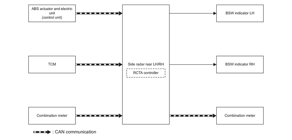
| Component | Description |
|---|---|
| TCM | TCM |
| ABS actuator and electric unit (control unit) | ABS Actuator and Electric Unit (Control Unit) |
| Combination meter (FULL TFT METER) | Combination Meter |
| Combination meter (7 INCH INFORMATION DISPLAY) | Combination Meter |
| Side radar rear LH/RH | Side Radar LH/RH |
| BSW indicator LH, RH | BSW Indicator LH/RH |
SIDE RADAR INPUT/OUTPUT SIGNAL ITEM
Input Signal Item
| Transmit unit | Signal name | Description | |
|---|---|---|---|
| TCM | CAN communication | Shift position signal | Receives a selector lever position |
| ABS actuator and electric unit (control unit) | CAN communication | Nissan Ariya Vehicle speed signal (ABS) | Receives wheel speeds of four wheels |
| Combination meter | CAN communication | System selection signal | Receives a selection state of each item selected through the Nissan Ariya vehicle information display |
Output Signal Item
| Reception unit | Signal name | Description | |
|---|---|---|---|
| Combination meter | CAN communication | Buzzer output signal | Transmits a signal to activate buzzer |
| BSW indicator LH, RH | BSW indicator signal | Transmits a BSW indicator signal to turn ON the BSW indicator | |
| BSW indicator dimmer signal | Transmits a BSW indicator dimmer signal to dimmer BSW indicator | ||
FUNCTION DESCRIPTION
-
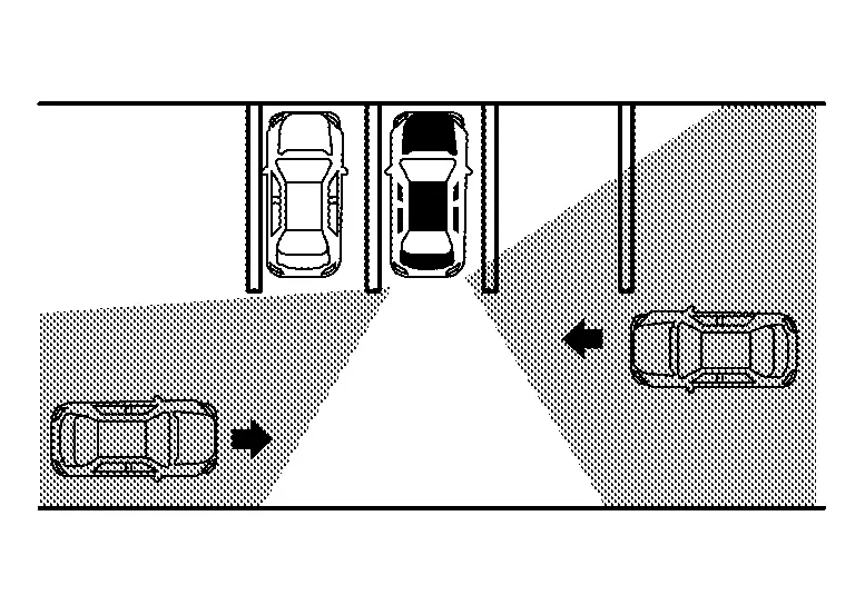
The Rear Cross Traffic Alert (RCTA) system can help alert the driver of approaching vehicles when the driver is backing out of a parking space.
-
The RCTA system uses side radars installed near the rear bumper to detect approaching Nissan Ariya vehicles.
-
The RCTA system operates at speeds below 8 km/h (5 MPH) whenever the vehicle is in reverse.
-
The side radar can detect Nissan Ariya vehicles on either side of vehicle within the detection zone shown as illustrated.
-
The radar sensors detect the approaching Nissan Ariya vehicle from up to approximately 20 m (66 ft) away.
-
If the radar detects a vehicle approaching from the side, the system gives visual and audible warning.
-
If the side radar detects an approaching Nissan Ariya vehicle from the side, the RCTA system sounds a beep (single beep), the BSW indicator on the side of the approaching Nissan Ariya vehicle flashes.
OPERATION DESCRIPTION
-
Side radar enables RCTA system.
-
Side radar starts the control as follows, based on a reverse gear signal and Nissan Ariya vehicle detection signal.
-
Side radar detects a vehicle approaching.
OPERATION CONDITION
Side radar performs the control when the following conditions are satisfied:
-
RCTA system: ON
-
Vehicle speed: Approximately 8 km/h (5 MPH) or less
-
Selector lever: “R” position
CANCEL CONDITION
The side radar cancels the operation when the system is under any conditions of the operation cancellation condition.
-
When the system malfunction occurs.
-
When the area around the side radar is dirty.
Tsr
System Description
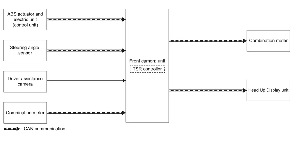
WITHOUT ProPILOT ASSIST 2.1
SYSTEM DIAGRAM
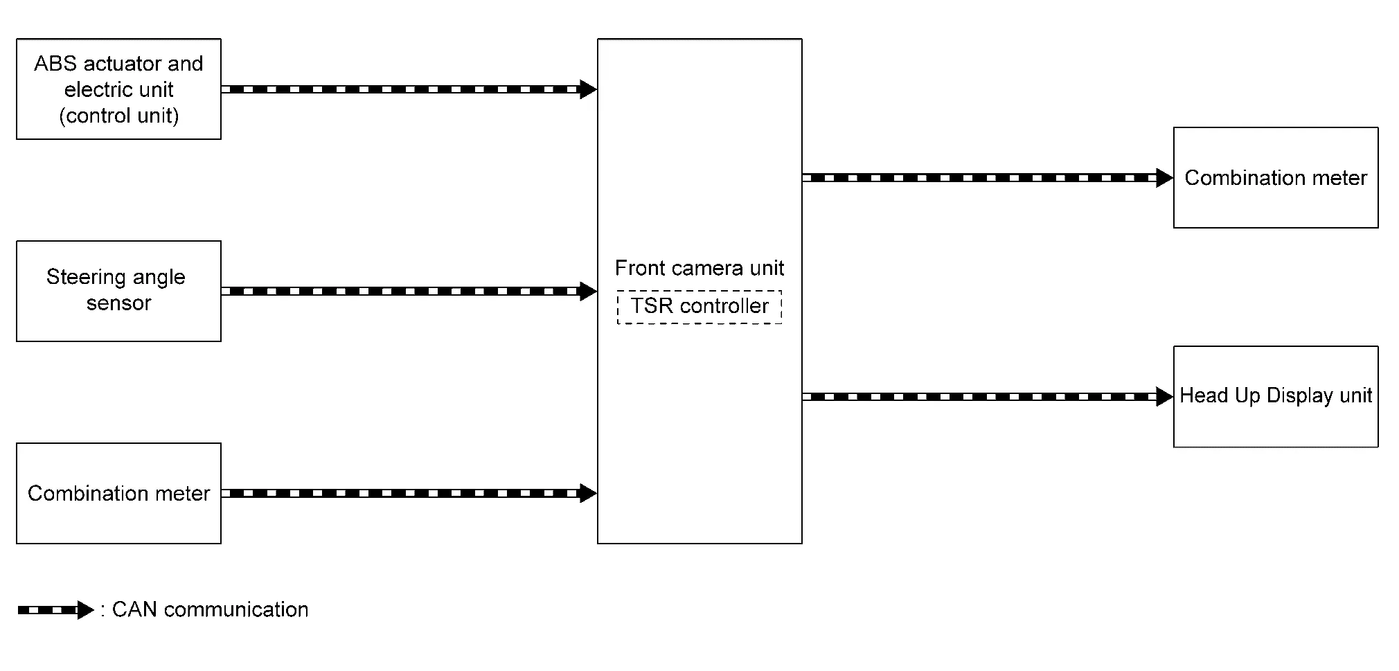
| Component | Description |
|---|---|
| ABS actuator and electric unit (control unit) | ABS Actuator and Electric Unit (Control Unit) |
| Steering angle sensor | Steering Angle Sensor |
| Combination meter (FULL TFT METER) | Combination Meter |
| Combination meter (7 INCH INFORMATION DISPLAY) | Combination Meter |
| Front camera unit | Front Camera Unit |
| Head Up Display unit | Head Up Display Unit |
FRONT CAMERA INPUT/OUTPUT SIGNAL ITEM
Input Signal Item
| Transmit unit | Signal name | Description | |
|---|---|---|---|
| ABS actuator and electric unit (control unit) | CAN communication | Nissan Ariya Vehicle speed signal (ABS) | Receives the wheel speed of the four wheels |
| Combination meter | CAN communication | System selection signal | Receives a selection state of each item selected with the combination meter |
| Steering angle sensor | CAN communication | Steering angle sensor signal | Receives the number of revolutions, turning direction of the steering wheel |
Output Signal Item
| Reception unit | Signal name | Description | |
|---|---|---|---|
| Combination meter | CAN communication | Meter display signal | Transmits a signal to display a state of the system on the information display |
| Buzzer output signal | Transmits a signal to activate buzzer | ||
| Head Up Display unit | CAN communication | Display signal | Transmits a signal to display a state of the system on the Head Up Display unit |
FUNCTION DESCRIPTION
-
Displays the road conditions as identified by the front camera unit on the information display, and alerts the driver. Identifies the road sign information.
-
The front camera unit detects road signs as described below and displays them on the information display.
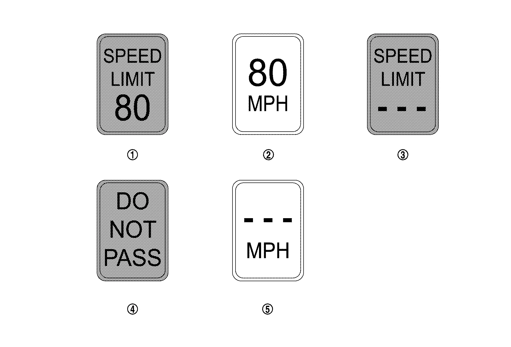

Latest detected speed limit 
Reduce speed limit caution (orange) 
No speed limit information 
No passing zone 
Reduce speed limit caution (with no speed limit information) (orange)
EXAMPLE
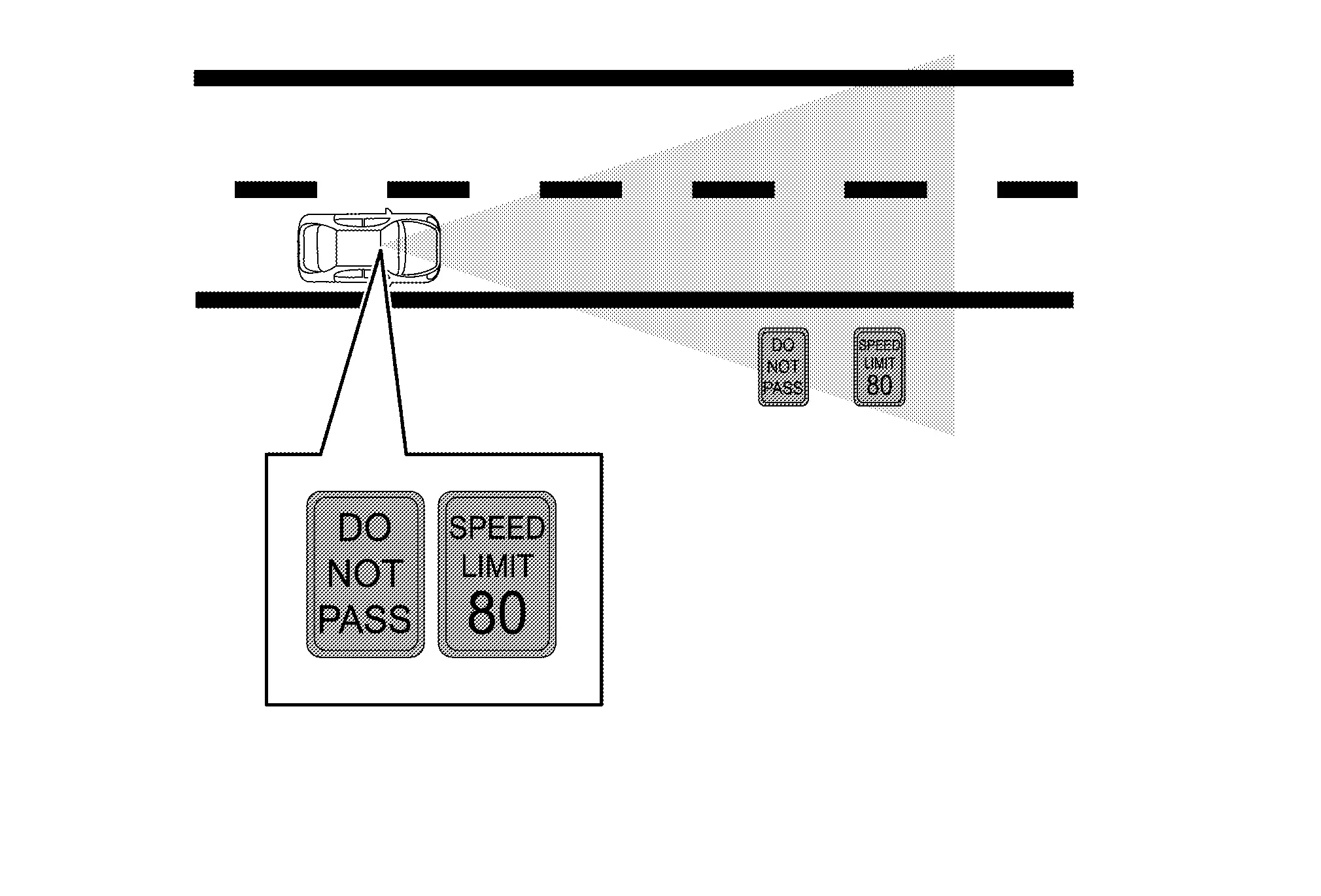
OPERATION DESCRIPTION
-
The TSR system is controlled by the front camera unit.
-
The front camera unit turns on the TSR system when the turned ON by combination meter.
-
The front camera unit detects the road sign.
-
The front camera unit transmits the meter display signal to the combination meter, when detecting the road sign.
-
The front camera unit adjusts the detection range of road signs according to a steering angle sensor signal received from the steering angle sensor.
OPERATION CONDITION
Front camera unit performs the control when the following conditions are satisfied.
-
TSR system: ON
NOTE:
-
TSR system ON/OFF can be set on the combination meter
-
The TSR system may not function properly, depending on the situation.
CANCEL CONDITION
The front camera unit cancels the operation when the system is under any conditions of the operation cancellation condition.
-
When the system malfunction occurs.
-
When the front camera unit becomes high temperature [over approximately 40 °C (104 °F)].
WITH ProPILOT ASSIST 2.1
SYSTEM DIAGRAM
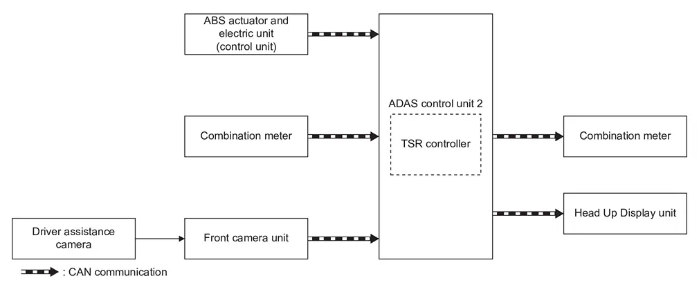
| Component | Description |
|---|---|
| ABS actuator and electric unit (control unit) | ABS Actuator and Electric Unit (Control Unit) |
| Steering angle sensor | Steering Angle Sensor |
| Combination meter |
|
| Front camera unit | Front Camera Unit |
| Driver assistance camera | Driver Assistance Camera |
| ADAS control unit 2 | ADAS Control Unit |
| Head Up Display unit | System Description |
ADAS CONTROL UNIT 2, FRONT CAMERA UNIT INPUT/OUTPUT SIGNAL ITEM
Input Signal Item
| Transmit unit | Reception unit | Signal name | Description | |
|---|---|---|---|---|
| ABS actuator and electric unit (control unit) | Front camera unit | CAN communication | Nissan Ariya Vehicle speed signal (ABS) | Receives the wheel speed of the four wheels |
| Combination meter | CAN communication | System selection signal | Receives a selection state of each item selected with the combination meter | |
| Steering angle sensor | CAN communication | Steering angle sensor signal | Receives the number of revolutions, turning direction of the steering wheel | |
| ABS actuator and electric unit (control unit) | ADAS control unit 2 | CAN communication | Nissan Ariya Vehicle speed signal (ABS) | Receives the wheel speed of the four wheels |
| Combination meter | CAN communication | System selection signal | Receives a selection state of each item selected with the combination meter | |
| Front camera unit | CAN communication | Traffic sign detection signal | Receives detection results of no-entry sign and speed sign | |
Output Signal Item
| Transmit unit | Reception unit | Signal name | Description | |
|---|---|---|---|---|
| Front camera unit | Combination meter | CAN communication | Meter display signal | Transmits a signal to display a state of the system on the information display |
| Buzzer output signal | Transmits a signal to activate buzzer | |||
| Display signal | Transmits a signal to display a state of the system on the Head Up Display unit | |||
| ADAS control unit 2 | Combination meter | CAN communication | Meter display signal | Transmits a signal to display a state of the system on the information display |
| Buzzer output signal | Transmits a signal to activate buzzer | |||
| Display signal | Transmits a signal to display a state of the system on the Head Up Display unit | |||
FUNCTION DESCRIPTION
-
Displays the road conditions as identified by the front camera unit on the information display, and alerts the driver. Identifies the road sign information.
-
The front camera unit detects road signs as described below and displays them on the information display.
Latest detected speed limit Reduce speed limit caution (orange) No speed limit information No passing zone Reduce speed limit caution (with no speed limit information) (orange)
EXAMPLE
OPERATION DESCRIPTION
-
The TSR system is controlled by the front camera unit.
-
The front camera unit turns on the TSR system when the turned ON by combination meter.
-
The front camera unit uses a driver assistance camera to detect road signs.
-
The front camera unit transmits the meter display signal to the combination meter, when detecting the road sign.
-
The front camera unit adjusts the detection range of road signs according to a steering angle sensor signal received from the steering angle sensor.
OPERATION CONDITION
Front camera unit performs the control when the following conditions are satisfied.
-
TSR system: ON
NOTE:
-
TSR system ON/OFF can be set on the combination meter
-
The TSR system may not function properly, depending on the situation.
CANCEL CONDITION
The front camera unit cancels the operation when the system is under any conditions of the operation cancellation condition.
-
When the system malfunction occurs.
-
When the front camera unit becomes high temperature [over approximately 40 °C (104 °F)].
I-Da
System Description
SYSTEM DIAGRAM
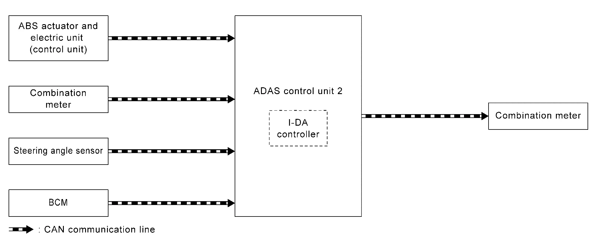
| Component | Description |
|---|---|
| BCM | System Description |
| Combination meter (FULL TFT METER) | Combination Meter |
| Combination meter (7 INCH INFORMATION DISPLAY) | Combination Meter |
| Steering angle sensor | Steering Angle Sensor |
| ABS actuator and electric unit (control unit) | ABS Actuator and Electric Unit (Control Unit) |
| ADAS control unit 2 | ADAS Control Unit 2 |
ADAS CONTROL UNIT 2 INPUT/OUTPUT SIGNAL ITEM
Input Signal Item
| Transmit unit | Signal name | Description | |
|---|---|---|---|
| ABS actuator and electric unit (control unit) | CAN communication | Nissan Ariya Vehicle speed signal (ABS) | Receives the wheel speed of the four wheels |
| Combination meter | CAN communication | System selection signal | Receives a selection state of each item selected with the combination meter |
| Steering angle sensor | CAN communication | Steering angle sensor signal | Receives the amount of rotation, rotational angle, and rotational direction of the steering wheel |
| BCM | CAN communication | Turn indicator signal | Receives an operational state of the turn signal lamp and hazard lamp |
Output Signal Item
| Reception unit | Signal name | Description | |
|---|---|---|---|
| Combination meter | CAN communication | Meter display signal | Transmits a signal and displays the status on the Nissan Ariya vehicle information display |
FUNCTION DESCRIPTION
-
Operates when the vehicle speed is 55 km/h (34 MPH) or higher.
-
Detects the steering status and judges the attentiveness of the driver. The driver's attentiveness is shown on the Nissan Ariya vehicle information display in eight stages (level indicator).
-
When it is judged from the degree of minor swerving in the steering operation that the Nissan Ariya vehicle is drifting, the driver is prompted to exert caution by the drift warning, which displays on the combination meter.
-
When the engine is stopped, the system is reset.
OPERATION DESCRIPTION
-
The I-DA (Intelligent Driver Alertness) is controlled by the ADAS control unit 2.
-
ON/OFF of the I-DA is performed by using the combination meter.
-
The steering angle sensor detects the degree of swerving in the steering operation.
-
When the ADAS control unit 2 judges that the steering operation is drifting it transmits the meter display signal to the combination meter.
OPERATION CONDITION
ADAS control unit 2 performs the control when the following conditions are satisfied.
-
I-DA system: ON
-
Vehicle speed: Approximately 55 km/h (34 MPH) or more
NOTE:
-
I-DA system ON/OFF can be set on the information display.
-
When the engine is stopped, the system is reset.
-
The I-DA system may not function properly, depending on the situation.
CANCEL CONDITION
The ADAS control unit 2 cancels the operation when the system is under any conditions of the operation cancellation condition.
-
When the system malfunction occurs.
Driver Monitor System
System Description
SYSTEM DIAGRAM
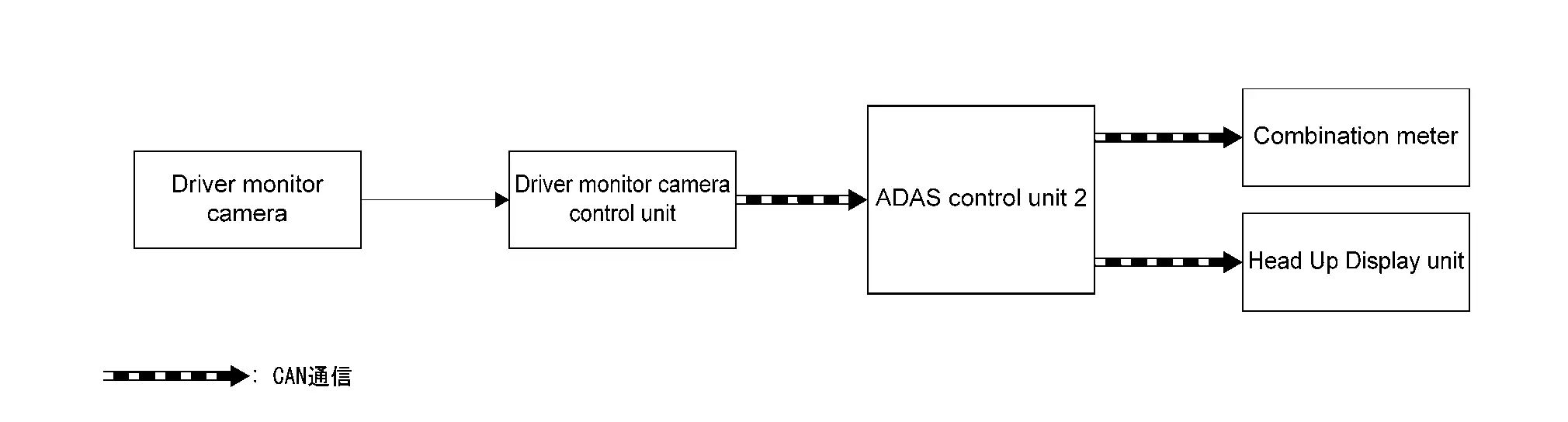
| Component | Description |
|---|---|
| Driver monitor camera | Refer to Driver Monitor Camera. |
| Driver monitor camera control unit | Refer to Driver Monitor Camera Control Unit. |
| ADAS control unit 2 | Refer to ADAS Control Unit. |
| Combination meter |
|
| Head Up Display unit | Refer to Head Up Display Unit. |
ADAS CONTROL UNIT 2 INPUT/OUTPUT SIGNAL ITEM
Input Signal Item
| Transmit unit | Signal name | Description | ||
|---|---|---|---|---|
| Driver monitor camera control unit | CAN communication | Aside warning signal | Receives a signal and monitors the driver's looking aside condition | |
| Doze warning signal | Receives a signal and monitors the driver's dozing condition | |||
Output Signal Item
| Reception unit | Signal name | Description | ||
|---|---|---|---|---|
| Combination meter | CAN communication | Buzzer output signal | Transmits signal to sound meter speaker. | |
| Meter display signal | Transmits signal to indicate warning on the Nissan Ariya vehicle information display. | |||
| Head Up Display unit | CAN communication | Display signal | Transmits signal to show the system status on the heads-up display | |
FUNCTION DESCRIPTION
-
The driver monitor system is a function that recognizes driver's condition by the driver monitor camera and supports safe driving.
-
When the system judges that the driver is dozing or looking aside by closing eyes for a certain period of time or turning the face away from the front while driving, the driver is warned by sound and display.
OPERATION DESCRIPTION
-
The driver monitoring system is controlled by ADAS control unit 2.
-
When ignition switch is ON, driver's condition is monitored by the driver monitor camera.
-
If the driver closes eyes for a certain period of time or turns face away from the front while the operating conditions of the driver monitor system are satisfied, the driver monitor camera control unit judges driver's dozing or looking aside, and transmits doze warning signal or aside warning signal to ADAS control unit 2.
-
When ADAS control unit 2 receives a signal from the driver monitor camera control unit, it transmits a meter display signal to combination meter and makes the combination meter display a warning.
-
ADAS control unit 2 transmits a buzzer output signal to the combination meter to make the buzzer sound.
OPERATION CONDITION
-
Doze warning
-
When the driver monitor system setting is ON
-
Shift position: D range
-
Driving (Nissan Ariya vehicle speed is more than 0 km/h)
-
-
Aside warning
-
When the driver monitor system setting is ON
-
Shift position: D range
-
Driving (Nissan Ariya vehicle speed is more than 0 km/h)
-
NOTE:
Even if the driver monitor system setting is OFF, a warning may be given when ProPILOT Assist 2.1 is operating.
Fail-safe (ADAS Control Unit)
Refer to Fail-Safe (ADAS Control Unit 2).
Fail-safe
If a malfunction occurs in the distance sensor, ADAS control unit 2 cancels control, sounds a beep, and turns ON the warning indicator on the information display.
Fail-safe
FAIL-SAFE CONTROL BY DTC
If a malfunction occurs in the front camera unit, ADAS control unit 2 cancels control, sounds a beep, and turns ON the warning indicator on the information display.
TEMPORARY DISABLED STATUS AT HIGH TEMPERATURE
-
If the vehicle is parked in direct sunlight under high temperature conditions, the system may be deactivated automatically. At this time, ADAS control unit 2 turns ON the AEB warning lamp and indicates the warning message on the information display.
-
When the interior temperature is reduced, the system will resume operation automatically.
-
When Nissan Ariya vehicle front identification is difficult due to soiling of windshield glass and strong light shining from the front, operation may be canceled temporarily. At this time, ADAS control unit 2 turns ON the AEB warning lamp.
Fail-safe (Side Radar)
FAIL-SAFE CONTROL BY DTC
If a malfunction occurs in the side radar, ADAS control unit 2 cancels control, sounds a beep, and turns ON the warning indicator on the information display.
TEMPORARY DISABLED STATUS AT BLOCKAGE
When the side radar is blocked, the operations of BSW/ RCTA systems are temporarily cancelled. Then the warning message is displayed on information display. Also, under the following conditions, the operation may be temporarily cancelled.
-
The side radar may be blocked by temporary ambient conditions such as splashing water, mist or fog.
-
The blocked condition may also be caused by objects such as ice, frost or dirt obstructing the side radar.
Fail-safe (Driver Monitor Camera Control Unit)
If a malfunction occurs in the driver monitor camera control unit, the driver monitor system will be canceled.
Other materials:
Engine oil
Checking engine oil level
Park the vehicle on a level area and apply the parking brake.
Warm up the engine to operating temperature.
Shut the engine off and wait at least 10 minutes.
Remove the dipstick, wipe it clean, then fully reinsert it.
Remove the dipstick again and check the oil le ...
Pre-Inspection for Diagnosis
Work Procedure
CHECK CAMERA LENS AND WINDSHIELD
Are camera lens and windshield contaminated with foreign materials?
YES (When the camera lens is contaminated with foreign materials.)>>
Replace front camera unit (Refer to Removal and Installation.) and GO TO 2.
YES (When the windshield ...
System Description. System
System Description (Heated Steering Wheel)
SYSTEM DIAGRAMThe
heated steering wheel switch controls the heated steering wheel relay.
When the heated steering wheel switch is turned on, the heated steering
wheel relay is energized and the heated steering wheel system will
operate. The heated ...