Nissan Rogue (T33) 2021-Present Service Manual: Component Parts
Driver Assistance System
Without Propilot Assist 2.1
Component Parts Location
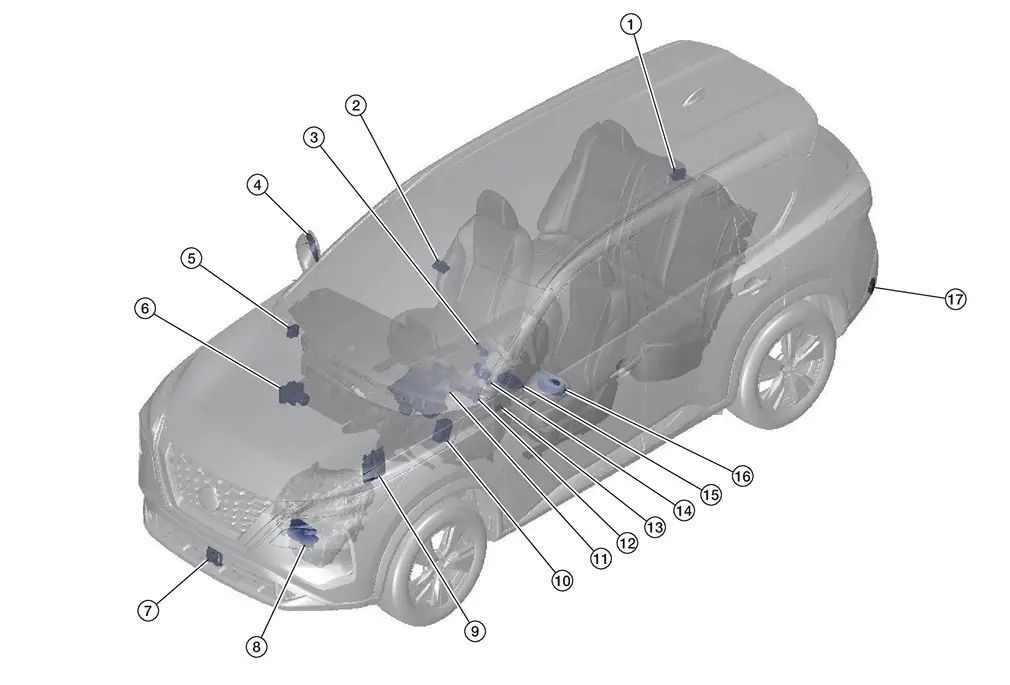
| No. | Component | Function |
|---|---|---|
| 1. | Side radar rear RH | Refer to Side Radar LH/RH. |
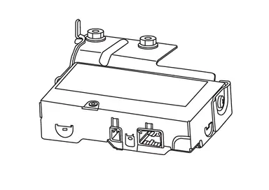
| 2. | Front camera unit | Refer to Front Camera Unit. |
| 3. | ProPILOT Assist 1.1 steering switch | Refer to Component Parts Location for detailed component location. |
| 4. | BSW (Blind Spot Warning) indicator RH | Refer to BSW Indicator LH/RH. |
| 5. | Chassis control module | Refer to Component Parts Location for detailed component location. |
| 6. | ABS (Anti-lock Braking System) actuator and electric unit (control unit) | Refer to Component Parts Location for detailed component location. |
| 7. | Distance sensor | Refer to Component Parts Location for detailed component location. |
| 8. | TCM (Transmission Control Module) | Refer to Component Parts Location for detailed component location. |
| 9. | ECM (Engine Control Module) | Refer to Component Parts Location for detailed component location. |
| 10. | BCM (Body Control Module) | Refer to Component Parts Location for detailed component location. |
| 11 | Head Up Display unit | Refer to Component Parts Location for detailed component location. |
| 12. | Combination meter |
Refer to Component Parts Location for detailed component location (Type A meter). Refer to Component Parts Location for detailed component location (Type B meter). |
| 13. | Steering assist switch | Refer to Steering Assist Switch. |
| 14. | Steering angle sensor | Refer to Component Parts Location for detailed component location. |
| 15. | ADAS (Advanced Driver Assistance System) control unit 2 | Refer to Component Parts Location for detailed component location. |
| 16. | BSW (Blind Spot Warning) indicator LH | Refer to BSW Indicator LH/RH. |
| 17. | Side radar rear LH | Refer to Side Radar LH/RH. |
With Propilot Assist 2.1
Component Parts Location
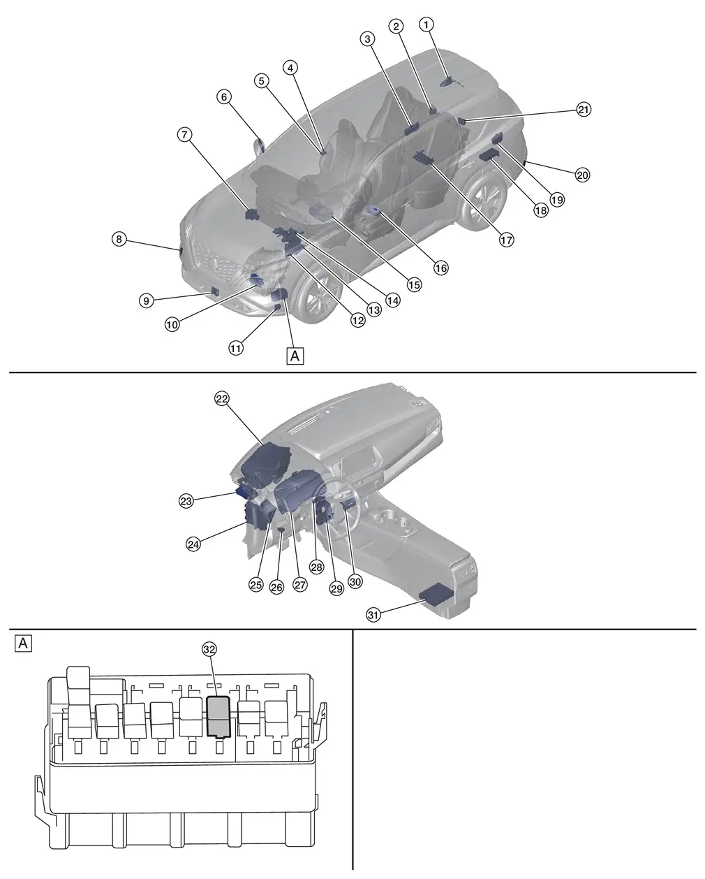
| A. | Behind front bumper fascia |
| No. | Component | Function |
|---|---|---|
| 1. | HD map antenna | Refer to HD MAP MODULE. |
| 2. | Side radar rear RH | Refer to Side Radar LH/RH. |
| 3. | Power network separate relay | Refer to POWER NETWORK SEPARATE RELAY. |
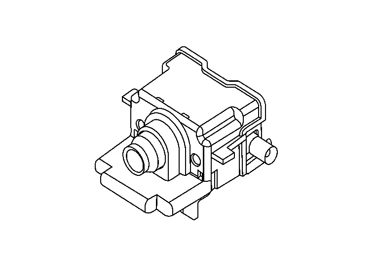
| 4. | Driver assistance camera | Refer to Driver Assistance Camera. |
| 5. | Heater | Refer to Front Camera Unit. |
| 6. | BSW (Blind Spot Warning) indicator RH | Refer to BSW Indicator LH/RH. |
| 7. | ABS (Anti-lock Braking System) actuator and electric unit (control unit) | Refer to Component Parts Location for detailed component location. |
| 8. | Side radar front RH | Refer to Side Radar LH/RH. |
| 9. | Distance sensor | Refer to Distance Sensor. |
| 10. | TCM (Transmission Control Module) | Refer to Component Parts Location for detailed component location. |
| 11. | Side radar front LH | Refer to Side Radar LH/RH. |
| 12. | ECM (Engine Control Module) | Refer to Component Parts Location for detailed component location. |
| 13. | IPDM E/R (Intelligent Power Distribution Module Engine Room) | Refer to Component Parts Location for detailed component location. |
| 14. | Electrically-Driven Intelligent Brake Unit | Refer to Component Parts Location for detailed component location. |
| 15. | 12V Sub battery (lithium ion battery) | Refer to Component Parts Location for detailed component location. |
| 16. | BSW (Blind Spot Warning) indicator LH | Refer to BSW Indicator LH/RH. |
| 17. | ADAS (Advanced Driver Assistance System) control unit 2 | Refer to Component Parts Location for detailed component location. |
| 18. | Front camera unit | Refer to Front Camera Unit. |
| 19. | HD map module | Refer to HD MAP MODULE. |
| 20. | Side radar rear LH | Refer to Side Radar LH/RH. |
| 21. | Sonar control unit | Refer to Component Parts Location for detailed component location. |
| 22. | Head Up Display unit | Refer to Component Parts Location for detailed component location. |
| 23. | Driver monitor camera control unit | Refer to Driver Monitor Camera Control Unit. |
| 24. | BCM (Body Control Module) | Refer to Component Parts Location for detailed component location. |
| 25. | Chassis control module | Refer to Component Parts Location for detailed component location. |
| 26. | Steering assist switch | Refer to Steering Assist Switch. |
| 27. | Combination meter | Refer to Component Parts Location for detailed component location. |
| 28. | Driver monitor camera | Refer to Driver Monitor Camera. |
| 29. | Steering angle sensor | Refer to Component Parts Location for detailed component location. |
| 30. | ProPILOT Assist 2.1 steering switch | Refer to ProPILOT Assist 2.1 Steering Switch. |
| 31. | Around view monitor control unit | Refer to Component Parts Location for detailed component location. |
| 32. | Shift actuator relay and stop lamp relay (stop lamp relay) |
|
Distance Sensor
FUNCTIONS WITHIN THE SYSTEM
-
Distance sensor transmits the presence/absence of vehicle ahead and the distance from the Nissan Ariya vehicle to ADAS control unit 2 via CAN communication.
INDIVIDUAL FUNCTIONS WITHIN THE SYSTEM
-
Distance sensor detects a vehicle ahead by using millimeter waves.
-
Distance sensor detects radar reflected from a Nissan Ariya vehicle ahead by irradiating radar forward and calculates a distance from the vehicle ahead and relative speed, based on the detected signal.
INDIVIDUAL OPERATION
-
AEB: System Description
-
ProPILOT Assist 1.1: System Description
-
I-FCW: System Description
PARTS LOCATION
Refer to Component Parts Location.
Side Radar LH/RH
FUNCTIONS WITHIN THE SYSTEM
-
Connected with the ADAS control unit 2 via CAN communication, the side radar transmits a Nissan Ariya vehicle detection signal.
-
Transmits an indicator operation signal to the BSW indicator LH/RH.
-
Side radar detects Nissan Ariya vehicle in the detection zone, and controls following systems.
-
BSW
-
I-BSI
-
RCTA
-
ProPILOT Assist 2.1
-
INDIVIDUAL FUNCTIONS WITHIN THE SYSTEM
-
The side radar detects other vehicles beside own vehicle in an adjacent lane.
-
Since side radar RH and side radar LH have the same specifications, side radar RH has the right/left switching signal circuit for identification.
INDIVIDUAL OPERATION
-
BSW: Refer to System Description.
-
I-BSI: Refer to System Description.
-
RCTA: Refer to System Description.
-
ProPILOT Assist 2.1: Refer to System Descriptionp-"System Description".
PARTS LOCATION
Refer to Component Parts Location.
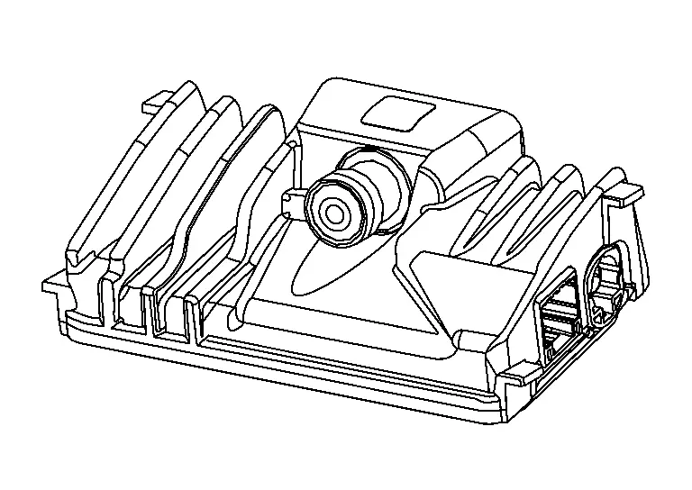
Front Camera Unit
WITHOUT ProPILOT ASSIST 2.1
FUNCTIONS WITHIN THE SYSTEM
Front camera unit the transmits the detected information to ADAS control unit 2 via CAN communication.
-
Front camera unit detects vehicle in the detection zone, and controls following systems.
-
AEB
-
ProPILOT Assist 1.1
-
LDW
-
I-LI
-
I-BSI
-
TSR
-
-
The heater output circuit is built in the front camera unit.
-
The front camera unit heats the heat wire built in the windshield glass to prevent condensation or fogging.
-
Condition of heater output
-
When front window defroster is used
-
When rear window defogger is used
-
When wiper is operated
-
When judging ambient temperature is low
-
When judging the front camera unit is shielded
-
INDIVIDUAL FUNCTIONS WITHIN THE SYSTEM
-
The multi-sensing front camera that can avoid various risks lurking forward and sideward with one camera is adopted.
-
Front camera unit is installed to windshield, and detects the lane marker in travel lane and pedestrian ahead.
-
When there is Nissan Ariya vehicle or pedestrian, front camera unit measures the distance from them.
INDIVIDUAL OPERATION
-
AEB: Refer to System Description.
-
ProPILOT Assist 1.1: Refer to System Description.
-
LDW: Refer to System Description.
-
I-LI: Refer to System Description.
-
I-BSI: Refer to System Description.
-
TSR: Refer to System Description.
PARTS LOCATION
Refer to Component Parts Location.
WITH ProPILOT ASSIST 2.1
FUNCTIONS WITHIN THE SYSTEM
-
The front camera unit obtains information of vehicle ahead and side.
-
Front camera unit detects Nissan Ariya vehicle in the detection zone, and controls following systems.
-
AEB
-
ProPILOT Assist 2.1
-
LDW
-
I-LI
-
I-BSI
-
TSR
-
-
The heater output circuit is built in the front camera unit.
-
The front camera unit heats the heat wire built in the windshield glass to prevent condensation or fogging.
-
Condition of heater output
-
When front window defroster is used
-
When rear window defogger is used
-
When wiper is operated
-
When judging ambient temperature is low
-
When judging the front camera unit is shielded
-
INDIVIDUAL FUNCTIONS WITHIN THE SYSTEM
-
The multi-sensing front camera that can avoid various risks lurking forward and sideward with one camera is adopted.
-
Front camera unit is installed to windshield, and detects the lane marker in travel lane and pedestrian ahead.
-
When there is Nissan Ariya vehicle or pedestrian, front camera unit measures the distance from them.
INDIVIDUAL OPERATION
-
AEB: Refer to System Description.
-
ProPILOT Assist 2.1: Refer to System Description.
-
LDW: Refer to System Description.
-
I-LI: Refer to System Description.
-
I-BSI: Refer to System Description.
-
TSR: Refer to System Description.
PARTS LOCATION
Refer to Component Parts Location.
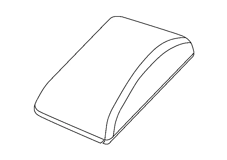
BSW Indicator LH/RH
FUNCTIONS WITHIN THE SYSTEM
-
The BSW indicator
 warns the driver by lighting/blinking.
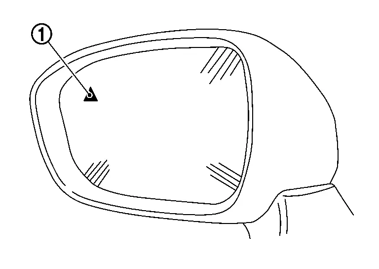
INDIVIDUAL FUNCTIONS WITHIN THE SYSTEM
-
Receives a BSW indicator operation signal from the side radar LH/RH and blinks or turns ON/OFF the BSW indicator.
INDIVIDUAL OPERATION
-
BSW: Refer to System Description.
-
I-BSI: Refer to System Description.
-
RCTA: Refer to System Description.
PARTS LOCATION
Refer to Component Parts Location.
Driver Monitor Camera
FUNCTIONS WITHIN THE SYSTEM
The driver monitor camera transmits the driver's video information to the driver monitor camera control unit while driving.
INDIVIDUAL FUNCTIONS WITHIN THE SYSTEM
The analog image information taken through the lens is converted to the digital signal and output.
INDIVIDUAL OPERATION
Driver monitor system: Refer to System Description.
PARTS LOCATION
Refer to Component Parts Location.
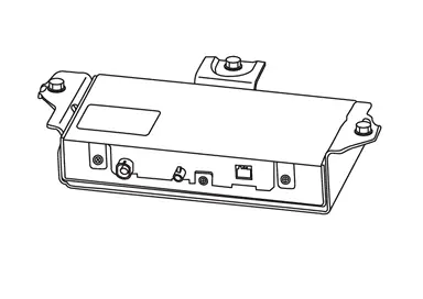
Driver Monitor Camera Control Unit
FUNCTIONS WITHIN THE SYSTEM
The driver monitor camera control unit judges driver's aside, dozing, etc. while driving based on the video information from driver monitor camera.
INDIVIDUAL FUNCTIONS WITHIN THE SYSTEM
The driver's condition is judged by image analysis.
INDIVIDUAL OPERATION
Driver monitor system: Refer to System Description.
PARTS LOCATION
Refer to Component Parts Location.
Driver Assistance Camera
FUNCTIONS WITHIN THE SYSTEM
-
The driver assistance camera inputs video data captured from the front and side of the vehicle as digital signals to the front camera unit.
-
Driver assistance camera detects Nissan Ariya vehicle in the detection zone, and controls following systems.
-
FEB
-
ProPILOT Assist 2.1
-
LDW
-
LDP
-
Blind Spot Intervention
-
TSR
-
RAB
-
INDIVIDUAL FUNCTIONS WITHIN THE SYSTEM
-
The multi-sensing driver assistance camera that can avoid various risks lurking forward and sideward with one camera is adopted.
-
Driver assistance camera is installed to windshield, and detects the lane marker in travel lane and pedestrian ahead.
-
When there is Nissan Ariya vehicle or pedestrian, driver assistance camera measures the distance from them.
INDIVIDUAL OPERATION
-
FEB: Refer to System Description.
-
ProPILOT Assist 2.1: Refer to System Description.
-
LDW: Refer to System Description.
-
LDP: Refer to System Description.
-
Blind Spot Intervention: Refer to System Description.
-
TSR: Refer to System Description.
-
RAB: Refer to System Description.
PARTS LOCATION
Refer to Component Parts Location.
Other materials:
Precaution. Precautions
Precaution for Supplemental Restraint System (SRS) "AIR BAG" and "SEAT BELT PRE-TENSIONER"
The Supplemental Restraint System such as ŌĆ£AIR BAGŌĆØ and ŌĆ£SEAT BELT
PRE-TENSIONERŌĆØ, used along with a front seat belt, helps to reduce the
risk or severity of injury to the driver and front passeng ...
Ext├®rieur avant
Cette vue avant du Nissan Rogue pr├®sente les ├®l├®ments de carrosserie, dŌĆÖ├®clairage et dŌĆÖaide ├Ā la conduite visibles depuis lŌĆÖavant du v├®hicule. Les ├®quipements marqu├®s dŌĆÖun ast├®risque peuvent d├®pendre de la finition.
Capot : acc├©s au compartiment moteur et aux points de con ...
Diagnosis System (av Control Unit)
Nissanconnect with 8" Color Display
On Board Diagnosis Function
The AV control unit on board diagnosis performs the functions listed in the table below:DESCRIPTION Mode Description
Self Diagnosis
Audio system diagnosis.
Diagnoses the connections across system components.
...