Nissan Rogue (T33) 2021-Present Service Manual: Memory Function
System Description
SYSTEM DIAGRAM
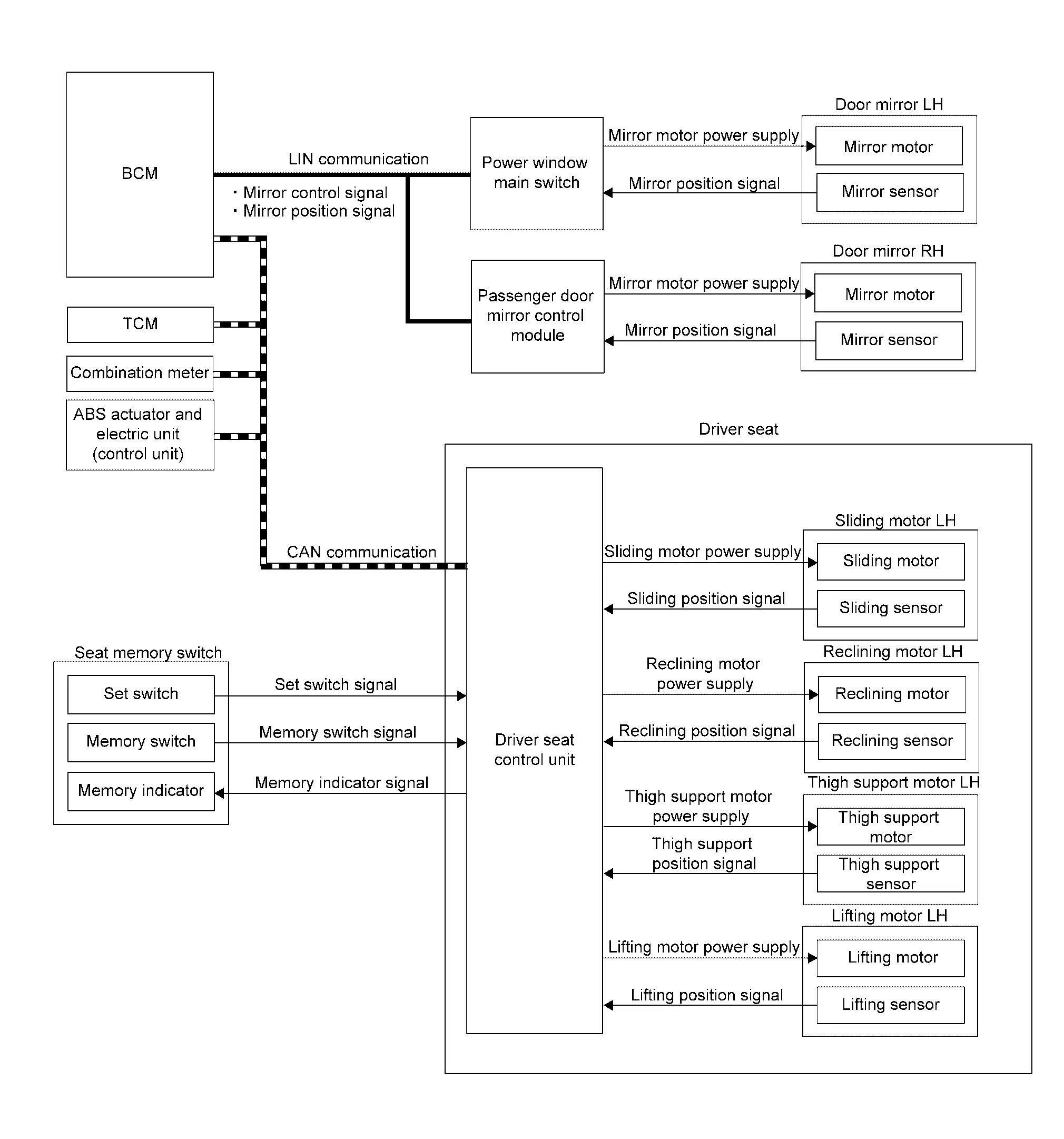
Several types of signals are transmitted from the following units to the driver seat control unit via CAN communication.
| Component | Signal |
|---|---|
| ABS actuator and electric unit (control unit) | Nissan Ariya Vehicle speed signal |
| Combination meter | Vehicle speed signal |
| BCM | Ignition switch signal |
| TCM | Shift position signal |
| Component | Function | |
|---|---|---|
| Door mirror LH | Mirror motor | It makes mirror face operate from side to side and up and down with the electric power that power window main switch supplies. |
| Mirror sensor |
|
|
| Door mirror RH | Mirror motor | It makes mirror face operate from side to side and up and down with the electric power that passenger door mirror control module supplies. |
| Mirror sensor |
|
|
| Seat memory switch | Set switch | Refer to Seat Memory Switch. |
| Memory switch | ||
| Memory indicator | ||
| Sliding motor LH | Sliding motor |
|
| Sliding sensor |
|
|
| Reclining motor LH | Reclining motor |
|
| Reclining sensor |
|
|
| Thigh support motor LH | Thigh support motor |
|
| Thigh support sensor |
|
|
| Lifting motor LH | Lifting motor |
|
| Lifting sensor |
|
|
| BCM |
|
|
| TCM | TCM transmits the shift position signal to driver seat control unit via CAN communication. | |
| Combination meter | Turns the driving position memory ON according to the request from driver seat control unit via CAN communication. | |
| ABS actuator and electric unit (control unit) | ABS actuator and electric unit (control unit) transmits the Nissan Ariya vehicle speed signal to driver seat control unit via CAN communication. | |
| Driver seat control unit | Refer to Driver Seat Control Unit. | |
| Power window main switch |
|
|
| Passenger door mirror control module |
|
|
DESCRIPTION
The driver seat control unit can store the optimum driving positions (seat and door mirror position) for 2 people. If the front seat position is changed, one-touch (pressing desired memory switch) operation allows changing to the other driving position.
 NOTE:
NOTE:
Further information for the memory storing procedure. Refer to Description.
Operation Procedure
-
Shift position P range.
-
Push memory switch 1 or 2.
-
Driver seat and door mirror will move to the memorized position.
Operation Condition
Satisfy all of the following items. The memory function is not performed if these items are not satisfied.
| Item | Status |
|---|---|
|
Switch inputs
|
OFF (Not operated) |
| Shift position | P range |
| Memory function | Registered |
| Nissan Ariya Vehicle speed | 0 MPH (0 km/h) |
| CONSULT | Not connected |
Detail Flow
| Order | Input | Output | Control unit condition |
|---|---|---|---|
| 1 | Memory switch | ŌĆö | The memory switch signal is inputted to the driver seat control unit when memory switch 1 or 2 is operated. |
| 2 | ŌĆö |
Motors (Seat, door mirror) |
Driver seat control unit operates each motor of seat when it recognizes the memory switch pressed for 0.5 second or more and requests each motor operation to BCM via CAN communication. The BCM transmits mirror control signal to power window main switch and passenger door mirror control module via LIN communication and actuates each motor according to the operation of the door mirror remote control switch. |
| Memory switch Indicator | Driver seat control unit requests the flashing of memory indicator while either of the motors is operating. The driver seat control unit illuminates the memory indicator. | ||
| 3 |
Sensors (Seat, door mirror) |
ŌĆö | Driver seat control unit judges the operating seat position with each seat sensor input. The positions of the door mirror is monitored with mirror sensor signal. Driver seat control unit stops the operation of each motor when each part reaches the recorded address. |
| 4 | ŌĆö | Memory switch Indicator | Driver seat control unit requests the illumination of memory indicator after all motors stop. The driver seat control unit illuminates the memory indicator for 5 seconds. |
Other materials:
P0335 Ckp Sensor 1
DTC Description
DTC DETECTION LOGIC DTC
CONSULT screen terms
(Trouble diagnosis content)
DTC detection condition
P0335
00
CKP SEN/CIRCUIT
(Crankshaft position sensor ŌĆ£AŌĆØ circuit)
Diagnosis condition
Engine running or cranking
Signal (terminal)
Crankshaft posit ...
P1c90-49 Sub Starter & Generator
DTC Description
DTC DETECTION LOGIC DTC No. CONSULT screen terms (Trouble diagnosis content) DTC detection condition
P1C90-49
Sub starter & generator
(Sub starter & generator)
Diagnosis condition
Engine running at idle
Signal (terminal)
-
Threshold
Sub starte ...
Cvt: Ge0f14a. Preparation. Preparation
Preparation
Special Service Tools
The actual shape of the tools may differ from those illustrated here.
Tool number
(TechMate No.)
Tool name Description
KV311039S0
(ŌĆāŌĆöŌĆā)
Charging pipe set
KV31103920*
(ŌĆāŌĆöŌĆā)
O-ring
CVT fluid changing and adjustment
...