Nissan Rogue (T33) 2021-Present Service Manual: Adas Control Unit :: Precaution. Precautions
Precautions
Precaution for Supplemental Restraint System (SRS) "AIR BAG" and "SEAT BELT PRE-TENSIONER"
The Supplemental Restraint System such as “AIR BAG” and “SEAT BELT PRE-TENSIONER”, used along with a front seat belt, helps to reduce the risk or severity of injury to the driver and front passenger for certain types of collisions.
Information necessary to service the system safely is included in the “SRS AIR BAG” and “SEAT BELT” sections of this Service Manual.
WARNING:
Always observe the following items for preventing accidental activation:
-
To avoid rendering the SRS inoperative, which could increase the risk of personal injury or death in the event of a collision that would result in air bag inflation, it is recommended that all maintenance and repair be performed by an authorized NISSAN/INFINITI dealer.
-
Improper repair, including incorrect removal and installation of the SRS, can lead to personal injury caused by unintentional activation of the system. For removal of Spiral Cable and Air Bag Module, see “SRS AIR BAG”.
-
Never use electrical test equipment on any circuit related to the SRS unless instructed to in this Service Manual. SRS wiring harnesses can be identified by yellow and/or orange harnesses or harness connectors.
PRECAUTIONS WHEN USING POWER TOOLS (AIR OR ELECTRIC) AND HAMMERS
WARNING:
Always observe the following items for preventing accidental activation:
-
When working near the Air Bag Diagnosis Sensor Unit or other Air Bag System sensors with the ignition/power switch ON or engine running, never use air or electric power tools or strike near the sensor(s) with a hammer. Heavy vibration could activate the sensor(s) and deploy the air bag(s), possibly causing serious injury.
-
When using air or electric power tools or hammers, always place the ignition/power switch in the OFF position, disconnect the 12V battery or batteries, and wait at least 3 minutes before performing any service.
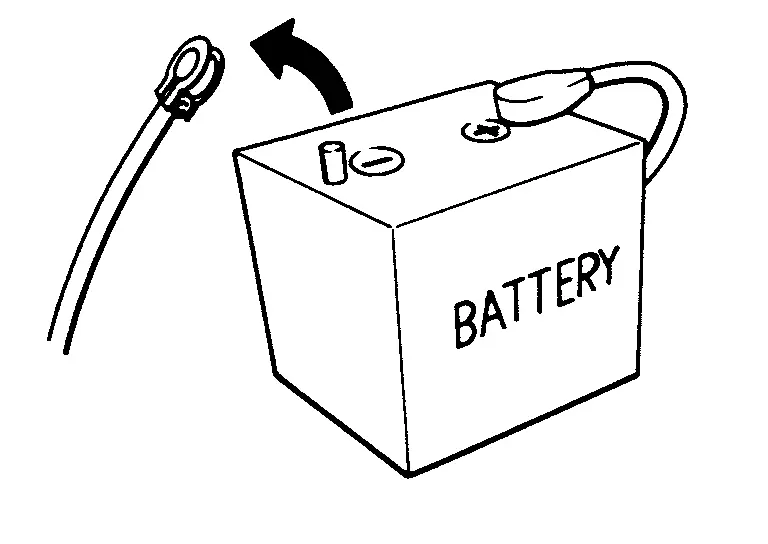
Precautions for Removing Battery Terminal
-
With the adoption of Auto ACC function, ACC power is automatically supplied by operating the Intelligent Key or remote keyless entry or by opening/closing the driver side door. In addition, ACC power is supplied even after the ignition switch is turned to the OFF position, i.e. ACC power is supplied for a certain fixed time.
-
When disconnecting the 12V battery terminal, turn off the ACC power before disconnecting the 12V battery terminal, observing “How to disconnect 12V battery terminal” described below.
 NOTE:
NOTE:
Some ECUs operate for a certain fixed time even after ignition switch is turned OFF and ignition power supply is stopped. If the battery terminal is disconnected before ECU stops, accidental DTC detection or ECU data damage may occur.
-
For Nissan Ariya vehicles with the 2-batteries, be sure to connect the main battery and the sub battery before turning ON the ignition switch.
NOTE:
If the ignition switch is turned ON with any one of the terminals of main battery and sub battery disconnected, then DTC may be detected.
-
After installing the 12V battery, always check "Self Diagnosis Result" of all ECUs and erase DTC.
NOTE:
The removal of 12V battery may cause a DTC detection error.
HOW TO DISCONNECT 12V BATTERY TERMINAL
Disconnect 12V battery terminal according to instruction described below.
-
Open the hood.
-
Turn ignition switch to the ON position.
-
Turn ignition switch to the OFF position with the driver side door opened.
-
Get out of the Nissan Ariya vehicle and close the driver side door.
-
Wait at least 3 minutes.
CAUTION:
While waiting, never operate the Nissan Ariya vehicle such as locking, opening, and closing doors. Violation of this caution results in the activation of ACC power supply according to the Auto ACC function.
-
Remove 12V battery terminal.
CAUTION:
After installing 12V battery, always check self-diagnosis results of all ECUs and erase DTC.
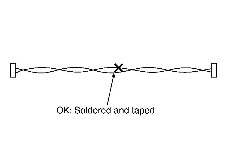
Precautions For Harness Repair
CAN communication uses a twisted pair line. Be careful when repairing it.
-
Solder the repaired area and wrap tape around the soldered area.
 NOTE:
NOTE:
A fray of twisted lines must be within 110 mm (4.33 in).
-
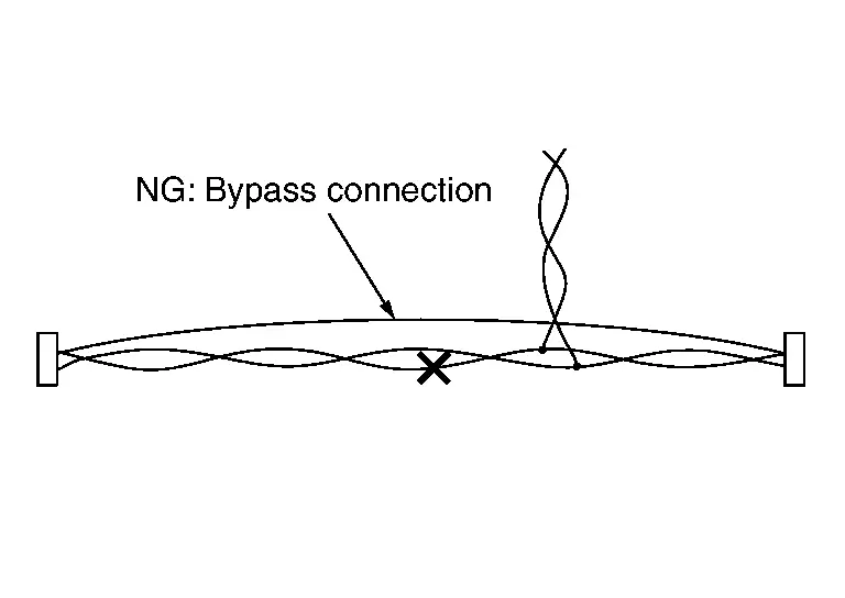
Bypass connection is never allowed at the repaired area.
 NOTE:
NOTE:
Bypass connection may cause CAN communication error. The spliced wire becomes separated and the characteristics of twisted line are lost.
Other materials:
Air Cleaner and Air Duct
Exploded View
1.
Air duct (Inlet)
2.
Clip
3.
Mounting rubber
4.
Mounting rubber
5.
Bracket
6.
Clip
7.
Air cleaner body
8.
Mounting rubber
9.
Collar
10.
Air cleaner filter
11.
Air cleaner cover
12.
Mass air flow sensor
...
Mode OFF-ROAD (modèles à transmission
intégrale)
Le mode OFF-ROAD du Nissan Rogue à transmission intégrale facilite la conduite et le démarrage sur des surfaces difficiles, telles que des chemins de terre irréguliers, des routes fortement dégradées, des montées raides ou encore des terrains meubles comme le sable. Ce mode adapte automatique ...
System Description. System
System Description (Heated Steering Wheel)
SYSTEM DIAGRAMThe
heated steering wheel switch controls the heated steering wheel relay.
When the heated steering wheel switch is turned on, the heated steering
wheel relay is energized and the heated steering wheel system will
operate. The heated ...