Nissan Rogue (T33) 2021-Present Service Manual: Manual Function
System Description
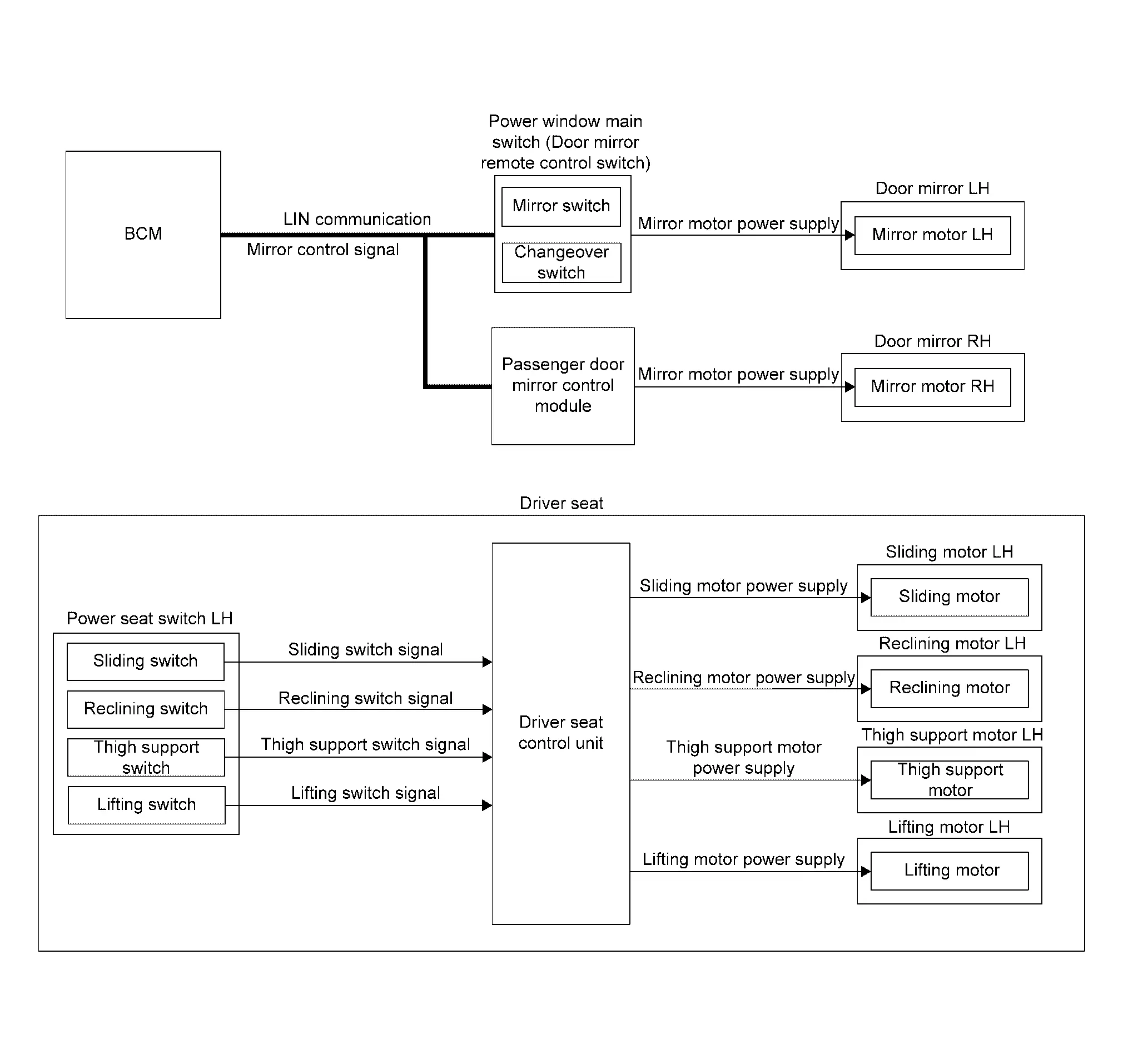
SYSTEM DIAGRAM
| Component | Function | |
|---|---|---|
| Power window main switch (door mirror remote control switch) |
|
|
| Passenger door mirror control module | Operates door mirror RH with the signal from the BCM. | |
| Door mirror LH | Mirror motor | It makes mirror face operate from side to side and up and down with the electric power that power window main switch supplies. |
| Door mirror RH | Mirror motor | It makes mirror face operate from side to side and up and down with the electric power that passenger door mirror control module supplies. |
| BCM |
|
|
| Power seat switch LH | Sliding switch | The operation signal is inputted to driver seat control unit when sliding switch is operated. |
| Reclining switch | The operation signal is inputted to driver seat control unit when reclining switch is operated. | |
| Thigh support switch | The operation signal is inputted to driver seat control unit when thigh support switch is operated. | |
| Lifting switch | The operation signal is inputted to driver seat control unit when lifting switch is operated. | |
| Sliding motor LH | Sliding motor |
|
| Reclining motor LH | Reclining motor |
|
| Thigh support motor LH | Thigh support motor |
|
| Lifting motor LH | Lifting motor |
|
| Driver seat control unit | Refer to Driver Seat Control Unit. | |
DESCRIPTION
The driving position (seat and door mirror position) can be adjusted manually with power seat switch LH and door mirror remote control switch.
Operation procedure
-
Operate power seat switch LH and door mirror remote control switch.
-
The driver seat or door mirror operates according to the operation of each switch.
 NOTE:
NOTE:
Seat operates only up to two places at the same time.
DETAIL FLOW
Seat
| Order | Input | Output | Control unit condition |
|---|---|---|---|
| 1 |
Power seat switch LH (Sliding, lifting, reclining, thigh support) |
ŌĆö | The power seat switch LH signal is inputted to the driver seat control unit when the power seat switch LH is operated. |
| 2 | ŌĆö |
Motors (Sliding, lifting, reclining, thigh support) |
The driver seat control unit outputs signals to each motor according to the power seat switch LH input signal. |
NOTE:
The power seat can be operated manually regardless of the ignition switch position.
Door Mirror
| Order | Input | Output | Control unit condition |
|---|---|---|---|
| 1 | Door mirror remote control switch | ŌĆö | The door mirror remote control switch signal received to the BCM via LIN communication when the door mirror remote control switch is operated. |
| 2 | ŌĆö |
Motor (Door mirror) |
The BCM transmits mirror control signal to power window main switch and passenger door mirror control module via LIN communication and actuates each motor according to the operation of the door mirror remote control switch. |
NOTE:
The door mirrors can be operated manually when ignition switch is ON or OFF (auto ACC status) position.
Other materials:
P2271 Ho2s2
DTC Description
The heated oxygen sensor 2 has a much longer switching time between
rich and lean than the air fuel ratio (A/F) sensor 1. The oxygen storage
capacity of the three way catalyst (manifold) causes the longer
switching time.
: 0.71 V
To judge the malfunctions of heated oxyge ...
Brake fluid
For more information on brake fluid type and capacity, refer to ŌĆ£Capacities and recommended fluids/lubricantsŌĆØ.
WARNING
Always use new brake fluid from a sealed container. Contaminated, old, or poor-quality fluid may damage the brake system and reduce stopping performance.
Clean the filler c ...
Modes de fonctionnement des essuie-glaces
Type A (selon ├®quipement)
Type B (selon ├®quipement)
Les commandes de visibilit├® de votre Nissan Rogue s'activent lorsque le contact est sur "ON" :
Mode AUTO / Intermittent :
- Type A (Automatique) : Le Nissan Rogue ajuste seul la vitesse selon l'intensit├® de la pluie ...