Nissan Rogue (T33) 2021-Present Service Manual: Type B :: Ecu Diagnosis Information. Combination Meter
Combination Meter
Reference Value
VALUES ON THE DIAGNOSIS TOOL
 NOTE:
NOTE:
The following table includes information (items) inapplicable to this Nissan Ariya vehicle. For information (items) applicable to this vehicle, refer to CONSULT display items.
| Monitor Item | Condition | Value/Status | |
|---|---|---|---|
|
SPEED METER [mph or km/h] |
Ignition switch ON | While driving | Input value of Nissan Ariya vehicle speed signal (CAN communication signal) |
|
Speed output [mph or km/h] |
Ignition switch ON | While driving | Output value of Nissan Ariya vehicle speed signal (CAN communication signal) |
|
Odometer output [mi or km] |
Ignition switch ON | ŌĆö | Output value of odometer signal (CAN communication signal) |
|
Tacho meter [rpm] |
Ignition switch ON | Engine running | Input value of engine speed signal (CAN communication signal) |
|
Fuel meter [L] |
Ignition switch ON | ŌĆö | Input value of fuel level sensor signal |
|
Water temperature meter [┬░F or ┬░C] |
Ignition switch ON | ŌĆö | Input value of engine coolant temperature signal (CAN communication signal) |
| ABS warning lamp | Ignition switch ON | ABS warning lamp ON | On |
| ABS warning lamp OFF | Off | ||
| VDC indicator | Ignition switch ON | VDC OFF indicator lamp ON | On |
| VDC OFF indicator lamp OFF | Off | ||
| VDC warning lamp | Ignition switch ON | VDC warning lamp ON | On |
| VDC warning lamp OFF | Off | ||
| Brake warning lamp | Ignition switch ON | Brake warning lamp ON | On |
| Brake warning lamp OFF | Off | ||
| Electric parking brake warning lamp | Ignition switch ON | Electric parking brake warning lamp ON | On |
| Electric parking brake warning lamp OFF | Off | ||
| Door warning | Ignition switch ON | During door open warning indication | On |
| Other than the above | Off | ||
| Trunk/glass hatch | Ignition switch ON |
This item is displayed, but cannot be monitored. |
Off |
| HI-BEAM IND | Ignition switch ON | High beam indicator lamp ON | On |
| High beam indicator lamp OFF | Off | ||
| Turn indicator | Ignition switch ON | Turn signal indicator lamp ON | On |
| Turn signal indicator lamp OFF | Off | ||
| Front fog lamp indicator | Ignition switch ON | Front fog lamp indicator lamp ON | On |
| Front fog lamp indicator lamp OFF | Off | ||
| Rear fog lamp indicator | Ignition switch ON |
This item is displayed, but cannot be monitored. |
Off |
| Position lamp indicator | Ignition switch ON | Position lamp indicator lamp ON | On |
| Position lamp indicator lamp OFF | Off | ||
| Engine oil pressure warning lamp | Ignition switch ON | During engine oil pressure warning indication | On |
| Except during engine oil pressure warning indication | Off | ||
| Malfunction indicator lamp (MIL) | Ignition switch ON | Malfunction indicator lamp ON | On |
| Malfunction indicator lamp OFF | Off | ||
| BA W/L | Ignition switch ON | AEB warning lamp ON | On |
| AEB warning lamp OFF | Off | ||
| Fuel warning lamp | Ignition switch ON | During low fuel warning indication | On |
| Other than the above | Off | ||
| Washer warning lamp | Ignition switch ON | During low washer warning indication | On |
| Except during low washer warning indication | Off | ||
| Low tire pressure warning lamp | Ignition switch ON | Low tire pressure warning lamp ON | On |
| Low tire pressure warning lamp OFF | Off | ||
| KEY GREEN/YELLOW WARNING LAMP | Ignition switch ON | During Intelligent Key system malfunction indication | On |
| Except during Intelligent Key system malfunction indication | Off | ||
| Power steering warning lamp | Ignition switch ON | Electric power steering warning lamp ON | On |
| Electric power steering warning lamp OFF | Off | ||
| DDS IND | Ignition switch ON |
This item is displayed, but cannot be monitored. |
Off |
| Charge warning lamp | Ignition switch ON | 12V battery charge warning lamp ON | On |
| 12V battery charge warning lamp OFF | Off | ||
| Electric parking brake indicator | Ignition switch ON | Electric parking brake indicator lamp ON | On |
| Electric parking brake indicator lamp OFF | Off | ||
| Brake oil switch | Ignition switch ON | Brake fluid level switch ON | On |
| Brake fluid level switch OFF | Off | ||
| Electric shift warning lamp (red) | Ignition switch ON | Electric shift warning lamp (red): ON | On |
| Other than the above | Off | ||
| LED LAMP RIGHT OPEN | Ignition switch ON | Front combination lamp RH malfunction | On |
| Other than the above | Off | ||
| LED LAMP LEFT OPEN | Ignition switch ON | Front combination lamp LH malfunction | On |
| Other than the above | Off | ||
| PASS BUCKLE SW | Ignition switch ON | Passenger seat belt not fastened | On |
| Passenger seat belt fastened | Off | ||
| CHG CONCT DET | Ignition switch ON |
This item is displayed, but cannot be monitored. |
Off |
|
Distance [km] or [mile] |
Ignition switch ON | ŌĆö | Distance to empty |
|
Outside temperature [┬░C or ┬░F] |
Ignition switch ON | ŌĆö | Displays the ambient air temperature which is input from the ambient sensor. |
| Buzzer | Ignition switch ON | Buzzer ON | On |
| Buzzer OFF | Off | ||
| Steering switch input | Ignition switch ON | Control switch is pressed | SW1 |
| Jog dial is rotated upward | SW2 | ||
| Jog dial is rotated downward | SW3 | ||
| OK switch is pressed | SW4 | ||
| LEFT/BACK switch is pressed | SW5 | ||
| RIGHT switch is pressed | SW6 | ||
| VOLUME DOWN switch is pressed | SW7 | ||
| VOLUME UP switch is pressed | SW8 | ||
| TEL switch is pressed | SW9 | ||
| VR switch is pressed | SW10 | ||
| SEEK DOWN switch is pressed | SW11 | ||
| SEEK UP switch is pressed | SW12 | ||
| Other than above | NO INPUT | ||
| High-beam assist indicator lamp | Ignition switch ON | High beam assist indicator lamp ON | On |
| High beam assist indicator lamp OFF | Off | ||
| DIPPED BEAM IND | Ignition switch ON |
This item is displayed, but cannot be monitored. |
Off |
| Engine Off timer | Ignition switch ON |
This item is displayed, but cannot be monitored. |
0 |
| Nissan Ariya Vehicle distance | Ignition switch ON |
This item is displayed, but cannot be monitored. |
0 |
| EAPM status | Ignition switch ON |
This item is displayed, but cannot be monitored. |
No spprt |
| Sonar detection status | Ignition switch ON | Sonar control unit detected the obstacle | On |
| Sonar control unit not detected the obstacle | Off | ||
| Sonar warning | Ignition switch ON | Sonar sensor error ON (sonar system ON) | ERROR |
| Sonar system OFF | DEACT | ||
| Sonar sensor error OFF (sonar system ON) | Off | ||
| Sonar detection display rear center | Ignition switch ON | Level of distance from center sensor rear to obstacle level1 | LEVEL1 |
| Level of distance from center sensor rear to obstacle level2 | LEVEL2 | ||
| Level of distance from center sensor rear to obstacle level3 | LEVEL3 | ||
| Level of distance from center sensor rear to obstacle level4 | LEVEL4 | ||
| Sonar detection display area rear left | Ignition switch ON | Obstacle is within the warning area of corner sensor rear LH | On |
| Other than above | Off | ||
| Sonar detection display rear right | Ignition switch ON | Level of distance from corner sensor rear RH to obstacle level1 | LEVEL1 |
| Level of distance from corner sensor rear RH to obstacle level2 | LEVEL2 | ||
| Level of distance from corner sensor rear RH to obstacle level3 | LEVEL3 | ||
| Level of distance from corner sensor rear RH to obstacle level4 | LEVEL4 | ||
| Sonar detection display area rear right [On/Off] | Ignition switch ON | Obstacle is within the warning area of corner sensor rear RH | On |
| Other than above | Off | ||
| Cranking signal | Ignition switch ON | When engine is cranking | On |
| Other than the above | Off | ||
| Electric shift warning lamp | Ignition switch ON | Electric shift warning lamp: ON | On |
| Other than the above | Off | ||
| Sonar setting available | Ignition switch ON | During the setting of the combination meter | Available |
| Other than the above | Unavailable | ||
| Starter control signal | Ignition switch ON | When starter control status signal is received from BCM via CAN communication. | On |
| Other than the above | Off | ||
| Front collision warning indicator lamp | Ignition switch ON | FCW system: ON | On |
| FCW system: blink | BLINK | ||
| FCW system: OFF | Off | ||
| Lane departure warning indicator lamp | Ignition switch ON | LDW system: ON | On |
| LDW system: blink | BLINK | ||
| LDW system: OFF | Off | ||
| ASCD SPEED BLINK | Ignition switch ON | Set Nissan Ariya vehicle speed indicator blinking | On |
| Set vehicle speed indicator not blinking | Off | ||
| ASCD STATUS | Ignition switch ON | ASCD system OFF | Off |
| ASCD system ON | ASCD | ||
| ASCD set Nissan Ariya vehicle speed | CRUISE | ||
| ASCD REQUEST SPEED | Ignition switch ON | While driving | Same value as ASCD or speed limiter set Nissan Ariya vehicle speed |
| ENGINE OIL CHG TMNG RST | Ignition switch ON | Resetting of a remaining distance to the engine oil change time. | On |
| Other than above | Off | ||
| Ecology drive navigator | Ignition switch ON | ŌĆö | LEVEL 0 - LEVEL 30 |
| Set forward emergency brake | Ignition switch ON | AEB setting is ON | On |
| AEB setting is OFF | Off | ||
| AEB is not available. | Not support | ||
| Set lane departure warning | Ignition switch ON | LDW setting is ON | On |
| LDW setting is OFF | Off | ||
| LDW is not available. | Not support | ||
| Set blind spot warning | Ignition switch ON | BSW setting is ON | On |
| BSW setting is OFF | Off | ||
| BSW is not available. | Not support | ||
| Set lane departure prevention | Ignition switch ON | I-LI setting is ON | On |
| I-LI setting is OFF | Off | ||
| I-LI is not available. | Not support | ||
| Blind spot warning indicator lamp | Ignition switch ON | BSW system display: ON | On |
| BSW system display: WARN ON | WARN ON | ||
| BSW system display: BLINK | BLINK | ||
| Other than above | Off | ||
| Lane departure prevention indicator lamp | Ignition switch ON | I-LI system display ON | On |
| Other than above | Off | ||
| Blind spot intervention indicator lamp | Ignition switch ON | I-BSI system display ON | On |
| Other than above | Off | ||
| Hands off warning lamp | Ignition switch ON | Hands off warning display: ON | On |
| Other than above | Off | ||
TERMINAL LAYOUT
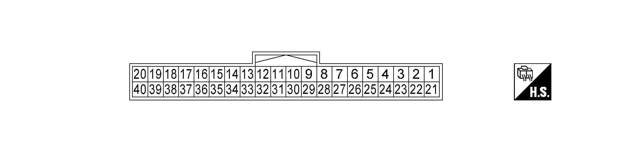
PHYSICAL VALUES
|
Terminal No. (Wire color) | Description | Condition |
Value (Approx.) | ||||
|---|---|---|---|---|---|---|---|
| + | ŌĆō | Signal name |
Input/ Output | ||||
|
1 (LA/G) |
Ground | Illumination control signal | Output | Ignition switch ON |
|
|
|
| ŌĆö | Battery voltage | ||||||
|
|
||||||
|
0 V | ||||||
|
3 (LA/Y) |
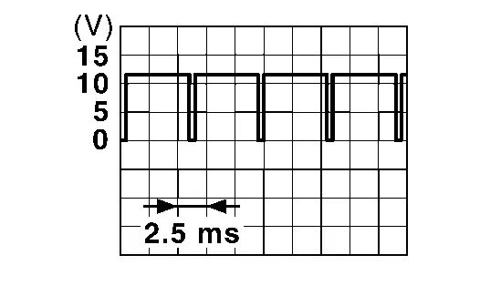
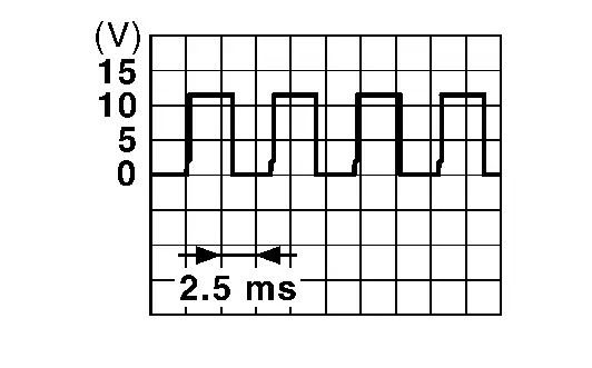
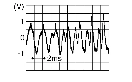
4 (LA/L) |
Meter speaker signal | Output |
[Ignition switch ON]
|
Outputs waveform synchronized with sound. |
|
|
|
5 (LA/G) |
Ground | Battery power supply | Input | Ignition switch OFF | ŌĆö | Battery voltage | |
|
6 (LA/BR) |
Ground | Ignition signal | Input | Ignition switch ON | ŌĆö | Battery voltage | |
|
7 (B) |
Ground | Ground | ŌĆö | ŌĆö | ŌĆö | 0 V | |
|
15* (Y) |
Ground | Washer level switch signal | Input | Ignition switch ON | Washer fluid level switch ON | 0 V | |
| Washer fluid level switch OFF | 12 V | ||||||
|
18 (LA/L) |
Ground | CAN-High | ŌĆö | ŌĆö | ŌĆö | ŌĆö | |
|
19 (LA/R) |
Ground | CAN-Low | ŌĆö | ŌĆö | ŌĆö | ŌĆö | |
|
23 (G) |
Ground | Steering switch signal B | Input | Ignition switch ON | Keep pressing VOLUME DOWN switch | 0 V | |
| Keep pressing VOLUME UP switch | 0.3 V | ||||||
| Keep pressing TEL switch | 0.6 V | ||||||
| Keep pressing VR switch | 1.1 V | ||||||
| Keep pressing SEEK DOWN switch | 2.0 V | ||||||
| Keep pressing SEEK UP switch | 3.3 V | ||||||
| Other than the above | 5.0 V | ||||||
|
25 (W) |
Ground | Illumination control switch signal (+) | Input | Ignition switch ON | Illumination control switch (+) is pressed | 0 V | |
| Other than the above | 5.0 V | ||||||
|
28 (V) |
Ground | Brake fluid level switch signal | Input | Ignition switch ON | Brake fluid level low | 5.0 V | |
| Brake fluid level normal | 12 V | ||||||
|
29 (SB) |
30 (P) |
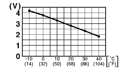
Ambient sensor signal | Input | Ignition switch ON | Changes depending to ambient temperature. |
|
|
|
30 (P) |
Ground | Ambient sensor ground | ŌĆö | Ignition switch ON | ŌĆö | 0 V | |
|
31 (R) |
Ground | Illumination control switch signal (ŌłÆ) | Input | Ignition switch ON | Illumination control switch (ŌłÆ) is pressed | 0 V | |
| Other than the above | 5.0 V | ||||||
|
32 (L) |
Ground | Illumination control switch ground | ŌĆö | Ignition switch ON | ŌĆö | 0 V | |
|
33 (BG) |
Ground | Steering switch signal A | Input | Ignition switch ON | Keep pressing control switch | 0 V | |
| Keep rotating jog dial upward | 0.3 V | ||||||
| Keep rotating jog dial downward | 0.6 V | ||||||
| Keep pressing OK switch | 1.1 V | ||||||
| Keep pressing LEFT/BACK switch | 2.0 V | ||||||
| Keep pressing RIGHT switch | 3.3 V | ||||||
| Other than the above | 5.0 V | ||||||
|
34 (GR) |
Ground | Steering switch ground | ŌĆö | Ignition switch ON | ŌĆö | 0 V | |
|
35 (LA/G) |
36 (LA/B) |
Fuel level sensor signal | Input | Ignition switch ON | Fuel gauge indication position | Full | Less than 94.5 Ōä” |
| 3/4 | 140 Ōä” | ||||||
| 1/2 | 186 Ōä” | ||||||
| 1/4 | 232 Ōä” | ||||||
| 1/8 | 255 Ōä” | ||||||
| Empty | More than 278 Ōä” | ||||||
|
36 (LA/B) |
Ground | Fuel level sensor ground | ŌĆö | Ignition switch ON | ŌĆö | 0 V | |
|
37 (LA/BR) |
38 (LA/Y) |
Oil level sensor signal | Input | Ignition switch ON | ŌĆö | Component Inspection | |
|
38 (LA/Y) |
Ground | Oil level sensor signal | ŌĆö | Ignition switch ON | ŌĆö | 0 V | |
|
39 (LA/LG) |
Ground | AV communication signal (L) | ŌĆö | ŌĆö | ŌĆö | ŌĆö | |
|
40 (LA/SB) |
Ground | AV communication signal (H) | ŌĆö | ŌĆö | ŌĆö | ŌĆö | |
*: For Canada
Fail-Safe
The combination meter activates the fail-safe control if CAN communication with each unit is malfunctioning.
| Function | Specifications | ||
|---|---|---|---|
| Speedometer | Reset to zero by suspending communication. | ||
| Tachometer | |||
| Engine coolant temperature gauge |
|
||
| Illumination control |
|
||
| Information display | Odometer | An indicated value is maintained at communications blackout. | |
| Shift position indicator | The display turns OFF by suspending communication. | ||
| Trip computer | Current Nissan Ariya vehicle speed | Reset to zero by suspending communication. | |
| Current fuel consumption | The last result calculated during normal condition is indicated. | ||
| Average fuel consumption | |||
| Average Nissan Ariya vehicle speed | |||
| ECO pedal guide | The display turns OFF by suspending communication. | ||
| Buzzer | The buzzer turns OFF by suspending communication. | ||
| Warning lamp/indicator lamp | ABS warning lamp | The lamp turns ON by suspending communication. | |
| VDC warning lamp | |||
| Brake warning lamp | |||
| Electric power steering warning lamp | |||
| Malfunction indicator lamp (MIL) | |||
| 12V battery charge warning lamp | |||
| Engine oil pressure warning lamp | |||
| SRS air bag warning lamp | |||
| Electric shift warning lamp | |||
| AEB warning lamp | |||
| Electric parking brake warning lamp | |||
| Low tire pressure warning lamp |
|
||
| Electric parking brake indicator lamp | The lamp blinking caused by suspending communication. | ||
| High beam indicator lamp | The lamp turns OFF by suspending communication. | ||
| Hands OFF warning lamp | |||
| High beam assist indicator lamp | |||
| VDC OFF indicator lamp | |||
| Turn signal indicator lamp | |||
| Front fog lamp indicator lamp | |||
| Position lamp indicator lamp | |||
| Seat belt warning lamp | |||
| Automatic brake hold indicator lamp | |||
DTC Inspection Priority Chart
If multiple DTCs are detected simultaneously, check them one by one depending on the following DTC inspection priority chart.
| Priority | Detected items (DTC) | |
|---|---|---|
| 1 |
|
|
| 2 |
|
|
| 3 |
|
|
| 4 |
|
|
| 5 |
|
|
| 6 |
|
|
DTC Index
| DTC | CONSULT display | Refer to |
|---|---|---|
| B2202-11 | Fuel level sensor | Refer to DTC Description. |
| B2202-13 | Fuel level sensor | Refer to DTC Description. |
| B2205-29 | Nissan Ariya Vehicle SPEED | Refer to DTC Description. |
| B2205-87 | Nissan Ariya Vehicle SPEED | Refer to DTC Description. |
| B220A-11 | ILLUMINATION OUTPUT CIRCUIT | Refer to DTC Description. |
| B220B-23 | Trip reset SW | Refer to DTC Description. |
| B220C-23 | Illumination up SW | Refer to DTC Description. |
| B220D-23 | Illumination down SW | Refer to DTC Description. |
| B2210-11 | Outside temp sens | Refer to DTC Description. |
| B221A-23 | Steering SW input1 | Refer to DTC Description. |
| B221B-23 | Steering SW input2 | Refer to DTC Description. |
| B2221-11 | Oil level sensor | Refer to DTC Description. |
| B2221-13 | Oil level sensor | Refer to DTC Description. |
| B2223-1C | Combination meter | Refer to DTC Description. |
| B2227-86 | AV communication | Refer to DTC Description. |
| B2227-87 | AV communication | Refer to DTC Description. |
| B2231-16 | Battery voltage | Refer to DTC Description. |
| B2231-17 | Battery voltage | Refer to DTC Description. |
| B2267-29 | TACHO METER | Refer to DTC Description. |
| B2267-87 | TACHO METER | Refer to DTC Description. |
| B2268-29 | WATER TEMP METER | Refer to DTC Description. |
| B2268-87 | WATER TEMP METER | Refer to DTC Description. |
| B226A-82 | ADAS CLK | Refer to DTC Description . |
| U1010-49 | CONTROL UNIT (CAN) | Refer to DTC Description. |
| U1321ŌĆō55 | Config unfinished | Refer to DTC Description. |
| DTC | CONSULT display | Refer to |
|---|---|---|
| U2118ŌĆō87 | CAN COMM CIRCUIT | Refer to DTC Description. |
| U213DŌĆō87 | CAN COMM CIRCUIT | Refer to DTC Description. |
| U2140ŌĆō87 | CAN COMM CIRCUIT | Refer to DTC Description. |
| U2141ŌĆō87 | CAN COMM CIRCUIT | Refer to DTC Description. |
| U2148ŌĆō87 | CAN COMM CIRCUIT | Refer to DTC Description. |
| U214AŌĆō87 | CAN COMM CIRCUIT | Refer to DTC Description. |
| U214FŌĆō87 | CAN COMM CIRCUIT | Refer to DTC Description. |
| U2150ŌĆō87 | CAN COMM CIRCUIT | Refer to DTC Description. |
| U2152ŌĆō83 | CAN COMM CIRCUIT | Refer to DTC Description. |
| U2152ŌĆō87 | CAN COMM CIRCUIT | Refer to DTC Description. |
| U2153ŌĆō87 | CAN COMM CIRCUIT | Refer to DTC Description. |
| U2154ŌĆō87 | CAN COMM CIRCUIT | Refer to DTC Description. |
| U2159ŌĆō87 | CAN COMM CIRCUIT | Refer to DTC Description. |
| U215BŌĆō87 | CAN COMM CIRCUIT | Refer to DTC Description. |
| U2165ŌĆō87 | CAN COMM CIRCUIT | Refer to DTC Description. |
| U216BŌĆō87 | CAN COMM CIRCUIT | Refer to DTC Description. |
| U216EŌĆō87 | CAN COMM CIRCUIT | Refer to DTC Description. |
| U2169ŌĆō87 | CAN COMM CIRCUIT | Refer to DTC Description. |
| U2173ŌĆō87 | CAN COMM CIRCUIT | Refer to DTC Description. |
| U2175ŌĆō87 | CAN COMM CIRCUIT | Refer to DTC Description. |
| U2176ŌĆō87 | CAN COMM CIRCUIT | Refer to DTC Description. |
| U2193ŌĆō87 | CAN COMM CIRCUIT | Refer to DTC Description. |
Other materials:
Combination Meter
Reference Value
VALUES ON THE DIAGNOSIS TOOLNOTE:
The following table includes information (items)
inapplicable to this Nissan Ariya vehicle. For information (items)
applicable to this vehicle, refer to CONSULT display items.
Monitor Item Condition Value/Status
SPEED METER
[mph or km/ ...
P040c Egr Temperature Sensor
DTC Description
DTC DETECTION LOGIC DTC
CONSULT screen terms
(Trouble diagnosis content)
DTC detection condition
P040C
00
EGR TEMP SENSOR A
(EGR temperature sensor A circuit low)
Diagnosis condition
ŌĆö
Signal (terminal)
ŌĆö
Threshold
ECM detects that a vo ...
Electric Shift Control Module
Exploded View
Electric shift control module
: N┬Ęm (kg-m, in-lb) : Vehicle front
Removal and Installation
REMOVALDisconnect the negative battery terminal. Refer to Exploded View.
Remove instrument side panel LH. Refer to Exploded View.
Disconnect the harn ...