Nissan Rogue (T33) 2021-Present Service Manual: Diagnosis System (combination Meter)
On Board Diagnosis Function
ON BOARD DIAGNOSIS ITEM
The following meter functions can be checked during combination meter self-diagnosis mode:
-
Pointer sweep of speedometer, tachometer and gauges.
-
Illumination of color patterns for meter displays.
-
Illumination of all lamps/LEDs that are controlled by the combination meter (regardless of switch status).
-
Error code
METHOD OF STARTING
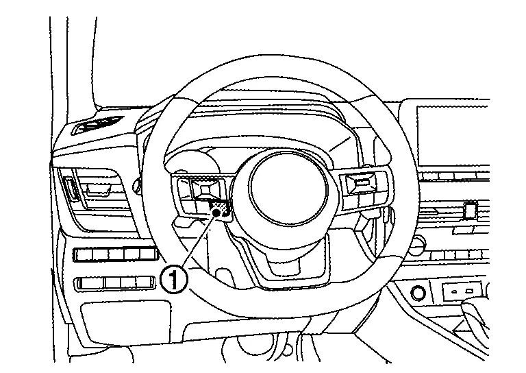
How to Initiate Self-Diagnosis Mode
-
Ignition switch OFF.
-
While pressing the control switch (1), place ignition switch ON.
-
Keep pressing the control switch for 1 seconds or more.
-
Press the control switch at least 3 times. (Within 7 seconds after placing the ignition switch ON).
-
ŌĆ£Work instruction codeŌĆØ is indicated in the top portion of information display and self-diagnosis is started.
 NOTE:
NOTE:
When on-board diagnosis does not start, check the following items and replace combination meter if the check results are normal.
-
Combination meter power supply and ground circuits. Refer to Diagnosis Procedure.
-
Steering switch signal circuits. Refer to Component Function Check.
-
-
The mode switches in the order shown below each time the control switch is pressed.
NOTE:
-
If the control switch is not operated for 20 seconds or more, the self-diagnosis mode is automatically cancelled.
-
The self-diagnosis mode is cancelled by placing the ignition switch OFF.
-
The self-diagnosis mode is cancelled by engine speed 170 rpm or more.
-
| Test order | Test item | Description | |
|---|---|---|---|
| 1 | Work instruction code | This item is displayed, but not used. | |
| 2 | Spare parts No. | ||
| Soft ware code | |||
| Flash rom No. | |||
| 3 | EEPROM code | ||
| 4 | Hardware code | ||
| 5 | PCB code | ||
| 6 | Circuit check |
The pointer of the following items moves from 0 to MAX then from MAX to 0.
If any one of the pointers does not sweep, replace combination meter. |
|
| 7 ŌĆō 10 | Color check | Performs the color check of the information display. | |
| 11 | Error code* |
Displays the error code of the following items.
|
|
| 12 | Warning/indicator lamp check |
All warning/indicator lamp illuminate.
Security indicator lamp are not illuminate. |
|
NOTE:
When the control switch is pressed during the indication of "Test order 12", test item returns to "Test order 2".
*: Error Code
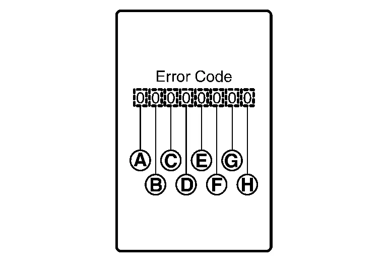
| Item | Code | Description | Action to take/Reference | |
|---|---|---|---|---|
 |
Speedometer | 0 | Normal | ŌĆö |
| 1 | A Nissan Ariya vehicle speed signal can not be received from ECM. |
Perform ŌĆ£Self diagnosis resultŌĆØ of ŌĆ£ECM.ŌĆØ Refer to DTC Index. |
||
| 2 | A Nissan Ariya vehicle speed signal received from ECM is abnormal. (FFFFh) | |||
 |
Tachometer | 0 | Normal | ŌĆö |
| 1 | An engine speed signal cannot be received from ECM. |
Perform ŌĆ£Self diagnosis resultŌĆØ of ŌĆ£ECM.ŌĆØ Refer to DTC Index. |
||
 |
Fuel gauge | 0 | Normal | ŌĆö |
| 1 | Fuel gauge circuit is short. | Refer to Component Function Check. | ||
| 2 | Fuel gauge circuit is open. | |||
 |
Engine coolant temperature gauge | 0 | Normal | ŌĆö |
| 1 | An engine coolant temperature signal cannot be received from ECM. |
Perform ŌĆ£Self diagnosis resultŌĆØ of ŌĆ£ECM.ŌĆØ Refer to DTC Index. |
||
 |
|
0 | Normal | ŌĆö |
| 1 | When judging that the illumination control switch signal circuit is short-circuited for 5 minutes or more. | Refer to Component Function Check. | ||
| 2 | When judging that the steering switch (control switch) signal circuit is short-circuited for 5 minutes or more. | Refer to Component Function Check. | ||
| 3 | When judging that the illumination control switch and steering switch (control switch) signal circuit are short-circuited for 5 minutes or more. | Refer to Component Function Check and Component Function Check. | ||
 |
ŌĆö | 0 | Displays ŌĆ£0ŌĆØ constantly. | ŌĆö |
 |
ŌĆö | 0 | Displays ŌĆ£0ŌĆØ constantly. | ŌĆö |
 |
ŌĆö | 0 | Displays ŌĆ£0ŌĆØ constantly. | ŌĆö |
CONSULT Function (M&A)
APPLICATION ITEMS
CONSULT can perform the following diagnosis modes via CAN communication and the combination meter.
| Diagnosis mode | Function | |||
|---|---|---|---|---|
| Self diagnosis result | The combination meter self diagnosis results are displayed. | |||
| ECU Identification | The combination meter part number is displayed. | |||
| Work supports | Lighting history of the warning lamp and indicator lamp can be checked. | |||
| Data Monitor | The combination meter input/output data is displayed in real time. | |||
| Replace ECU | Writes the Nissan Ariya vehicle specification when replacing the combination meter. | |||
SELF DIAGNOSIS RESULT
Refer to DTC Index.
ECU IDENTIFICATION
The combination meter part number is displayed.
WORK SUPPORTS
| Work support item | Function |
|---|---|
| OTA status reset |
This item is displayed, but cannot be monitored. |
WARNING HISTORY
-
Stores histories when warning/indicator lamp is turned on.
-
ŌĆ£WARNING HISTORYŌĆØ indicates the ŌĆ£TIMEŌĆØ when the warning/ indicator lamp is turned on.
-
The ŌĆ£TIMEŌĆØ above is:
-
0: The condition that the warning/indicator lamp has been turned on 1 or more times after starting the engine and waiting for 30 seconds.
-
1 - 39: The number of times the engine was restarted after the 0 condition.
-
NO WARNING HISTORY: Stores NO (0) turning on history of warning/indicator lamp.
-
NOTE:
-
WARNING HISTORY is not stored for approximately 30 seconds after the engine starts.
-
Brake warning lamp does not store any history when the parking brake is applied or the brake fluid level gets low.
| Display item | Description |
|---|---|
| ABS warning lamp | Lighting history of ABS warning lamp. |
| VDC indicator | Lighting history of VDC OFF indicator lamp. |
| SLIP indicator | Lighting history of VDC warning lamp. |
| Brake warning lamp | Lighting history of brake warning lamp. |
| Engine oil pressure warning lamp | Lighting history of engine oil pressure warning lamp. |
| Malfunction indicator lamp (MIL) | Lighting history of malfunction indicator lamp (MIL). |
| BA W/L | Lighting history of AEB warning lamp. |
| Low tire pressure warning lamp | Lighting history of low tire pressure warning lamp. |
| Power steering warning lamp | Lighting history of electric power steering warning lamp. |
| Charge warning lamp | Lighting history of 12V battery charge warning lamp. |
NOTE:
In items displayed on the CONSULT screen, only those listed in the above table are used.
Freeze frame data (FFD)
When DTC is detected, the following vehicle condition is recorded and it is displayed on the CONSULT screen.
| Item name | Display item | |
|---|---|---|
| ODO/TRIP METER |
Records an odometer value when DTC is detected.
|
|
| DTC count | Records the number of times DTC was detected. | |
DATA MONITOR
NOTE:
The following table includes information (items) inapplicable to this Nissan Ariya vehicle. For information (items) applicable to this vehicle, refer to CONSULT display items.
Display Item List
X: Applicable
| Display item [Unit] |
MAIN SIGNALS | Description |
|---|---|---|
|
SPEED METER [mph or km/h] |
X |
Value of Nissan Ariya vehicle speed signal received from ECM via CAN communication.
655.35 is displayed when the malfunction signal is received. |
|
Speed output [mph or km/h] |
X |
Nissan Ariya Vehicle speed signal value transmitted to other units via CAN communication.
655.35 is displayed when the malfunction signal is received. |
|
Odometer output [mi or km] |
Odometer signal received from ABS actuator and electric unit (control unit) via CAN communication. | |
|
Tacho meter [rpm] |
X |
Value of the engine speed signal received from ECM via CAN communication.
8191.875 is displayed when the malfunction signal is received. |
|
Fuel meter [L] |
X | Fuel level indicated on combination meter. |
|
Water temperature meter [┬░F or ┬░C] |
X |
Value of engine coolant temperature signal is received from ECM via CAN communication.
215 is displayed when the malfunction signal is input. |
|
ABS warning lamp [On/Off] |
Status of ABS warning lamp detected from ABS warning lamp signal is received from ABS actuator and electric unit (control unit) via CAN communication. | |
|
VDC indicator [On/Off] |
Status of VDC OFF indicator lamp detected from VDC OFF indicator lamp signal is received from ABS actuator and electric unit (control unit) via CAN communication. | |
|
VDC warning lamp [On/Off] |
Status of VDC warning lamp detected from VDC warning lamp signal received from ABS actuator and electric unit (control unit) via CAN communication. | |
|
Brake warning lamp [On/Off] |
Status of brake warning lamp detected from brake warning lamp signal is received from ABS actuator and electric unit (control unit) via CAN communication and brake fluid level switch signal from brake fluid level switch.
Displays ŌĆ£OffŌĆØ if the brake warning lamp is illuminated when the valve check starts, the parking brake switch is turned ON or the brake fluid level switch is turned ON. |
|
|
Electric parking brake warning lamp [On/Off] |
Status of electric parking brake warning lamp detected from electric parking brake warning lamp signal from electric parking brake control module via CAN communication. | |
|
Door warning [On/Off] |
Status of door open warning detected from door switch signal received from BCM via CAN communication. | |
|
Trunk/glass hatch [Off] |
This item is displayed, but cannot be monitored. |
|
|
HI-BEAM IND [On/Off] |
Status of high beam indicator lamp detected from high beam status signal is received from BCM via CAN communication. | |
|
Turn indicator [On/Off] |
Status of turn signal indicator lamp detected from turn indicator signal is received from BCM via CAN communication. | |
|
Front fog lamp indicator [On/Off] |
Status of front fog lamp indicator lamp detected from front fog light status signal is received from BCM via CAN communication. | |
|
Rear fog lamp indicator [Off] |
This item is displayed, but cannot be monitored. |
|
|
Position lamp indicator [On/Off] |
Status of position lamp indicator lamp detected from position light status signal is received from BCM via CAN communication. | |
|
Engine oil pressure warning lamp [On/Off] |
Status of engine oil pressure warning detected from engine oil pressure warning lamp signal is received from ECM via CAN communication. | |
|
Malfunction indicator lamp [On/Off] |
Status of malfunction indicator lamp detected from malfunctioning indicator lamp signal is received from ECM via CAN communication. | |
|
BA W/L [On/Off] |
Status of AEB warning lamp judged from AEB warning lamp signal received from ADAS control unit via CAN communication. | |
|
Washer warning lamp [On/Off] |
Status of low washer fluid warning judged from washer level switch input to combination meter. | |
|
Low tire pressure warning lamp [On/Off] |
Status of low tire pressure warning lamp judged from low tire pressure lamp signal received from BCM via CAN communication. | |
|
KEY GREEN/YELLOW WARNING LAMP [On/Off] |
Status of Intelligent Key system malfunction detected from meter display signal is received from BCM via CAN communication. | |
|
Power steering warning lamp [On/Off] |
Status of electric power steering warning lamp detected from electric power steering warning lamp signal is received from EPS control unit via CAN communication. | |
|
DDS W/L [Off] |
This item is displayed, but cannot be monitored. |
|
|
Charge warning lamp [On/Off] |
Status of 12V battery charge warning lamp judged from battery warning request signal received from ECM or IPDM E/R via CAN communication. | |
|
Electric parking brake indicator [On/Off] |
Status of electric parking brake indicator lamp detected from electric parking brake indicator lamp signal from electric parking brake control module via CAN communication. | |
|
Brake oil switch [On/Off] |
Status of brake fluid level switch. | |
|
Electric shift warning lamp (red) [On/Off] |
Status of electric shift warning lamp (red) detected from electric shift warning lamp signal received from electric shift control module via CAN communication. | |
|
LED LAMP RIGHT OPEN [On/Off] |
Status of front combination lamp RH judged based on headlamp warning signal input from IPDM E/R via CAN communication. | |
|
LED LAMP LEFT OPEN [On/Off] |
Status of front combination lamp LH judged based on headlamp warning signal input from IPDM E/R via CAN communication. | |
|
PASS BUCKLE SW [On/Off] |
Status of front seat belt buckle switch (passenger side) detected from passenger seat belt buckle switch signal from air bag diagnosis sensor unit via CAN communication. | |
|
CHG CONCT DET [Off] |
This item is displayed, but cannot be monitored. |
|
|
DISTANCE [km] |
Value of distance to empty calculated by combination meter. | |
|
Outside temperature [┬░F or ┬░C] |
Ambient temperature value converted from ambient sensor signal received from ambient sensor.
This may not match with the temperature value indicated on the information display. (Because the information display value is a corrected value from the ambient sensor input value.) |
|
|
Cranking signal [On/Off] |
Cranking status is displayed. | |
|
Starter control signal [On/Off] |
Starter control status judged from starter control status signal is received from BCM via CAN communication. | |
|
Buzzer [On/Off] |
X | Buzzer status (in the combination meter) is detected from the buzzer output signal received from each unit via CAN communication and the warning output condition of the combination meter. |
|
Parking assist display [On/Off] |
Status of sonar display received from sonar control unit via CAN communication. | |
|
Parking assist sensor [Off/Rear/FRONT/On/Not support] |
Activation status of sonar system received from sonar control unit via CAN communication. | |
|
Parking assist volume [High/Medium/Low/Not support] |
Status of sonar volume received from sonar control unit via CAN communication. | |
|
Parking assist range [Far/Medium/Near/Not support] |
Status of sonar range received from sonar control unit via CAN communication. | |
|
Electric shift warning lamp [On/Off] |
Status of electric shift warning lamp detected from electric shift warning lamp signal received from electric shift control module via CAN communication. | |
|
Sonar setting available [Available/Unavailable] |
Status of sonar setting of combination meter. | |
|
Steering switch input [SW1-SW12, NOT INPUT] |
Status of steering switch. | |
|
High-beam assist indicator lamp [On/Off] |
Status of high beam assist indicator lamp from high beam assist indicator lamp signal is received from BCM via CAN communication. | |
|
Sonar detection status [On/Off] |
Activation status of sonar system received from sonar control unit via CAN communication. | |
|
Sonar warning [Off/DEACT/ERROR] |
Status of parking sensor error detected from parking sensor error signal is received from sonar control unit via CAN communication. | |
|
Sonar detection display rear center [LEVEL1/LEVEL2/LEVEL3/LEVEL4] |
Status of center sensor rear detection obstacle from sonar control unit via CAN communication. | |
|
Sonar detection display area rear center [On/Off] |
Activation status of center sensor rear judged from a sonar indicator signal received from the sonar control unit via CAN communication. | |
|
Sonar detection display rear left [LEVEL1/LEVEL2/LEVEL3/LEVEL4] |
Status of corner sensor rear LH detection obstacle from sonar control unit via CAN communication. | |
|
Sonar detection display area rear left [On/Off] |
Activation status of corner sensor rear LH judged from a sonar indicator signal received from the sonar control unit via CAN communication. | |
|
Sonar detection display rear right [LEVEL1/LEVEL2/LEVEL3/LEVEL4] |
Status of corner sensor rear RH detection obstacle from sonar control unit via CAN communication. | |
| Sonar detection display area rear right [On/Off] | Activation status of corner sensor rear RH judged from a sonar indicator signal received from the sonar control unit via CAN communication. | |
|
Sonar distance display [Off/stop/30cm/40cm/50cm/60cm] |
Sonar of information display of sonar sensor detection distance from sonar control unit via CAN communication. | |
|
Front collision warning indicator lamp [WARN ON/BLINK/On/Off] |
Status of FCW system display detected from meter display signal is received from ADAS control unit 2 via CAN communication. | |
|
Lane departure warning indicator lamp [WARN ON/BLINK/On/Off] |
Status of LDW system display detected from meter display signal is received from ADAS control unit 2 via CAN communication. | |
|
ASCD SPEED BLINK [On/Off] |
Blinking status of ASCD set Nissan Ariya vehicle speed judged by the ASCD status signal received from ECM via CAN communication. | |
|
ASCD STATUS [Off, SL On, SL sus, SL inhi, CC On, CC sus, CC inhi, N/A] |
Status of ASCD status display judged by the ASCD status signal received from ECM via CAN communication. | |
|
ASCD REQUEST SPEED [km/h] |
ASCD set Nissan Ariya vehicle speed value judged by the ASCD status signal received from ECM via CAN communication. | |
|
ENGINE OIL CHG TMNG RST [On/Off] |
Resetting of a remaining distance to the engine oil change time. | |
|
DIPPED BEAM IND [Off] |
This item is displayed, but cannot be monitored. |
|
| Engine Off timer |
This item is displayed, but cannot be monitored. |
|
| Nissan Ariya Vehicle distance |
This item is displayed, but cannot be monitored. |
|
|
EAPM status [No spprt] |
This item is displayed, but cannot be monitored. |
|
|
Set forward emergency brake [On/Off/Not support] |
Status of AEB system setting. | |
|
Set lane departure warning [On/Off/Not support] |
Status of LDW system setting. | |
|
Set blind spot warning [On/Off/Not support] |
Status of BSW system setting. | |
|
Set lane departure prevention [On/Off/Not support] |
Status of iŌĆÉLI system setting. | |
|
Blind spot warning indicator lamp [WARN ON/BLINK/On/Off] |
Status of BSW system display detected from meter display signal is received from ADAS control unit 2 via CAN communication. | |
|
Lane departure prevention indicator lamp [On/Off] |
Status of I-LI system display detected from meter display signal is received from ADAS control unit 2 via CAN communication. | |
|
Blind spot intervention indicator lamp [On/Off] |
Status of I-BSI system display detected from meter display signal is received from ADAS control unit 2 via CAN communication. | |
|
Hands off warning lamp [On/Off] |
Status of hands off warning lamp. |
REPLACE ECU
Writes the vehicle specification when replacing the combination meter.
Other materials:
R├®glages
Informations de base
Le mode de r├®glages permet ├Ā lŌĆÖutilisateur de personnaliser les informations affich├®es sur lŌĆÖ├®cran dŌĆÖinformations du v├®hicule ainsi que plusieurs param├©tres de fonctionnement du Nissan Rogue. Ces r├®glages offrent une adaptation fine du v├®hicule selon vos pr├®f├®re ...
Can Gateway. Precaution. Precautions
Precautions
PRECAUTIONS FOR SUPPLEMENTAL RESTRAINT SYSTEM (SRS) AIR BAG AND SEAT BELT PRE-TENSIONER
: Precautions
The Supplemental Restraint System such as ŌĆ£AIR BAGŌĆØ and ŌĆ£SEAT BELT
PRE-TENSIONERŌĆØ, used along with a front seat belt, helps to reduce the
risk or severit ...
U0402 Can Communication
DTC Description
DTC DETECTION LOGIC DTC
CONSULT screen terms
(Trouble diagnosis content)
DTC detection condition
U0402
00
Invalid data (TCM)
(Invalid Data Received From TCM)
Diagnosis condition
Ignition switch ON
Signal (terminal)
ŌĆö
Threshold
When ECM is ...