Nissan Rogue (T33) 2021-Present Service Manual: B24c6-12 Blower Motor Control
DTC Description
DTC DETECTION LOGIC
| DTC No. |
CONSULT screen terms (Trouble diagnosis content) | DTC detection condition | ||
|---|---|---|---|---|
| B24C6тАУ12 |
BLOWER MOTOR CONTROL (Blower motor control) |
[CIRCUIT SHORT TO GROUND] | Diagnosis condition | When ignition switch is ON |
| Signal (Terminal) | Blower motor control signal | |||
| Threshold | Blower motor control signal circuit has a short to ground | |||
| Diagnosis delay time | тАФ | |||
POSSIBLE CAUSE
-
Harness or connectors (blower motor control signal circuit is shorted to ground)
-
A/C amp.
FAIL-SAFE
тАФ
DTC CONFIRMATION PROCEDURE
PERFORM SELF DIAGNOSIS RESULT
 CONSULT
-
Ignition switch ON.
-
Select тАЬSelf diagnosis resultтАЭ mode of тАЬHVACтАЭ.
-
Check DTC.
Is DTC detected?
YES>>Refer to DTC Diagnosis Procedure.
NO-1>>To check malfunction symptom before repair: Refer to Intermittent Incident.
NO-2>>Confirmation after repair: Inspection End.
DTC Diagnosis Procedure
CHECK FRONT BLOWER MOTOR CONTROL SIGNAL
-
Ignition switch ON.
-
Check duty ratios between front blower motor harness connector and ground by using an oscilloscope.
(+) (тИТ) Condition Output waveform
(Approx.)Front blower motor Connector Terminal M144 1 Ground Front blower motor: OFF Battery voltage Front blower motor: 1st speed (manual) 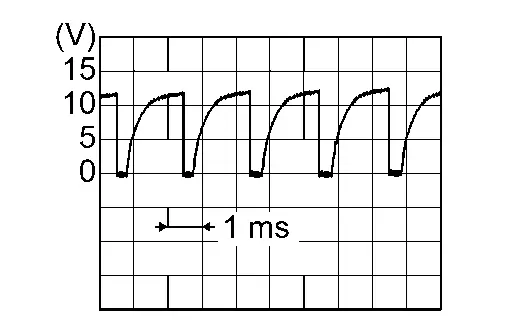
Front blower motor: 7th speed (manual) 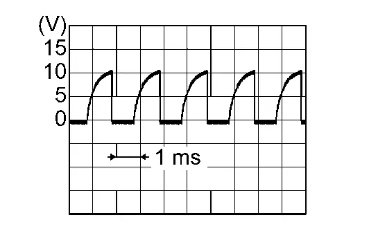
Is the inspection result normal?
YES>>Replace front blower motor. Refer to Removal and Installation.
NO>>GO TO 2.
CHECK FRONT BLOWER MOTOR CONTROL SIGNAL CIRCUIT FOR OPEN
-
Ignition switch OFF.
-
Disconnect front blower motor connector and A/C amp. connector.
-
Check continuity between front blower motor harness connector and A/C amp. harness connector.
Front blower motor A/C amp. Continuity Connector Terminal Connector Terminal M144 1 M50 34 Yes -
Check continuity between front blower motor harness connector and ground.
Front blower motor (тАФ) Continuity Connector Terminal M144 1 Ground Yes
Is the inspection result normal?
YES>>Replace the A/C amp. Refer to Removal and Installation.
NO>>Repair the harnesses or connectors.
Other materials:
P11b1 Vcr Target Angle (cold Start)
DTC Description
DTC DETECTION LOGIC DTC
CONSULT screen terms
(Trouble diagnosis content)
DTC detection condition
P11B1
00
VCR target angle (cold start)
[Variable compression ratio target angle (cold start)]
Diagnosis condition
Engine running at idle
Signal (terminal) ...
Removal and Installation. Air Bag Diagnosis Sensor Unit
Exploded View
1.
Air bag diagnosis sensor unit
тАФ
тАФ
тАФ
тАФ
: Nissan Ariya Vehicle front
: Always replace after every disassembly.
: N┬╖m (kg-m, in-lb)
Removal and Installation
WARNING:
Always observe the following items for preventing accidental acti ...
B2205-29 Vehicle Speed
DTC Description
DTC DETECTION LOGIC DTC No.
CONSULT screen terms
(Trouble diagnosis content) DTC detected condition
B2205-29
SPEED METER
(Speed meter)
Diagnosis condition
When ignition switch is ON.
Signal (terminal)
Nissan Ariya Vehicle speed display signal
Threshold ...