Nissan Rogue (T33) 2021-Present Service Manual: Automatic Drive Positioner
System Description
SYSTEM DIAGRAM
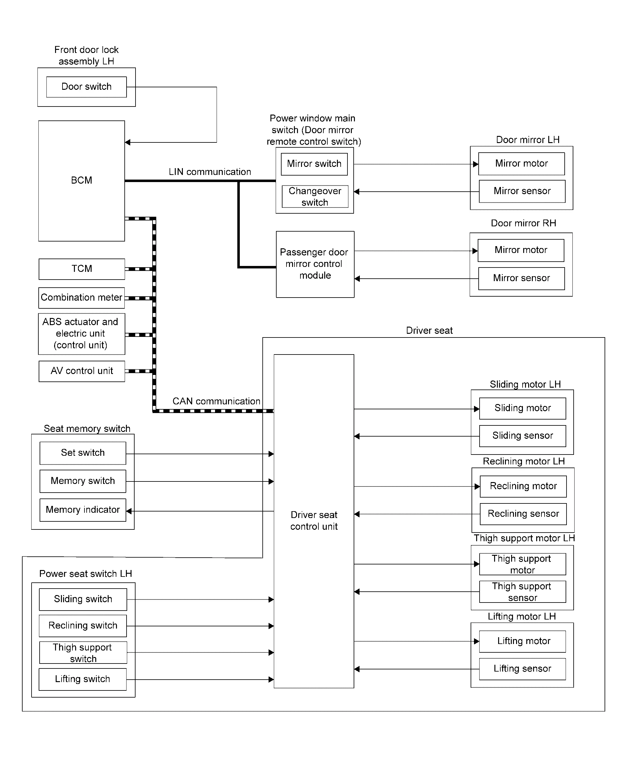
Several types of signals are transmitted from the following units to the driver seat control unit via CAN communication.
| Component | Signal |
|---|---|
| ABS actuator and electric unit (control unit) | Nissan Ariya Vehicle speed signal |
| Combination meter | Vehicle speed signal |
| AV control unit | Edit user information |
| BCM | Ignition switch signal |
| TCM | Shift position signal |
DESCRIPTION
Automatic drive positioner system adjusts the driver seat and door mirrors.
The following functions can be easily changed for the preset driving positions.
| Function | Description | |
|---|---|---|
| Manual function |
The driving position (seat and door mirror position) can be adjusted by using the power seat switch LH or door mirror remote control switch. For details on manual function, refer to System Description. |
|
| Memory function |
The seat and door mirror move to the stored driving position by pressing seat memory switch (1 or 2).
For models with navigation system, the seat position set with the seat memory switch cannot be operated interlocked with the Intelligent Key. For details on memory function, refer to System Description. |
|
| Entry/exit assist function | Exit |
On exit, the seat moves backward. For details on exit assist function, refer to System Description. |
| Entry |
On entry, the seat returns from exiting position to the previous driving position. For details on entry assist function, refer to System Description. |
|
| Log-in function (with navigation system) |
The driving position can be registered and retrieved for each Intelligent Key. For details on log-in function, refer to System Description. |
|
| Intelligent Key interlock function | With navigation system |
When Intelligent Key interlock function performs the following function, it causes the exit assist function to operate.
Registered information of the driving position is retrieved from the memory registered to the driver seat control unit by the log-in function. For details on Intelligent Key interlock function, refer to System Description. |
| Without navigation system |
Perform memory operation, exiting operation and entry operation by Intelligent Key unlock operation or front door request switch (front door LH) unlock operation. For details on Intelligent Key interlock function, refer to System Description. |
|
 NOTE:
NOTE:
The lumbar support system are controlled independently with no link to the automatic drive positioner system. Refer to System Description.
Sleep control
Driver seat control unit is equipped with sleep control for reducing power consumption.
The system switches to sleep control when all of the following conditions are satisfied.
-
Ignition switch OFF and open/close the driver side door.
-
All devices of auto driving position system are not operating.
-
Set switch and memory switch (1 and 2) are OFF.
Wake-up control
Sleep control cancels when detecting a status change in any of the following items.
-
CAN communication
-
Power seat switch LH
-
Set switch and seat memory switch (1 and 2)
Other materials:
Installing top tether strap
WARNING
Child restraint anchorages are designed only for correctly installed restraints. Never attach adult seat belts or other equipment to these points—doing so may damage the anchors and compromise safety.
Avoid hooking the tether strap on the seatback carpet. Always use the designated ...
P1c90-49 Sub Starter & Generator
DTC Description
DTC DETECTION LOGIC DTC No. CONSULT screen terms (Trouble diagnosis content) DTC detection condition
P1C90-49
Sub starter & generator
(Sub starter & generator)
Diagnosis condition
Engine running at idle
Signal (terminal)
-
Threshold
Sub starte ...
P0053 A/f Sensor 1 Heater
DTC Description
DTC DETECTION LOGIC DTC
CONSULT screen terms
(Trouble diagnosis content)
DTC detection condition
P0053
00
HO2S1 HTR B1
(HO2S heater resistance bank 1 sensor 1)
Diagnosis condition
—
Signal (terminal)
A/F sensor 1 heater signal
Threshold
D ...