Nissan Rogue (T33) 2021-Present Service Manual: P2270 Ho2s2
DTC Description
The heated oxygen sensor 2 has a much longer switching time between rich and lean than the air fuel ratio (A/F) sensor 1. The oxygen storage capacity of the three way catalyst (manifold) causes the longer switching time.
MALFUNCTION A
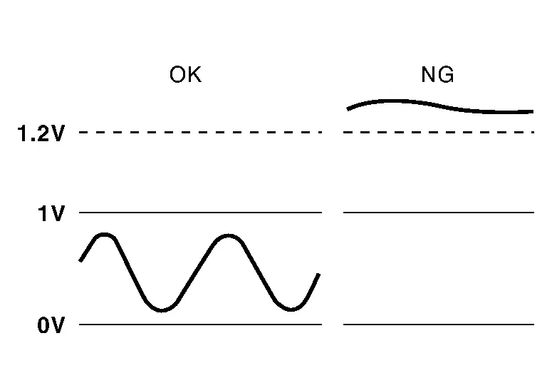
To judge the malfunctions of heated oxygen sensor 2, ECM monitors whether the voltage is unusually high during various driving conditions such as fuel cut.
MALFUNCTION B
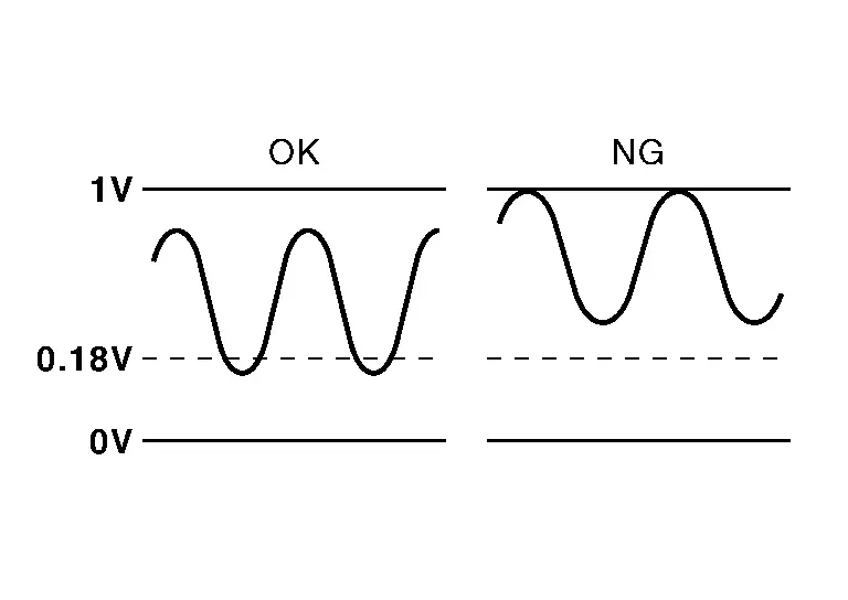
To judge the malfunctions of heated oxygen sensor 2, ECM monitors whether the minimum voltage is excessively high during various driving conditions such as fuel cut.
DTC DETECTION LOGIC
| DTC |
CONSULT screen terms (Trouble diagnosis content) |
DTC detection condition | |||
| P2270 | 00 |
O2 sensor signal bank 1 sensor 2 (O2 Sensor Signal Biased/Stuck Lean Bank 1 Sensor 2) |
A | Diagnosis condition | Engine running at fuel cut |
| Signal (terminal) | Heated oxygen sensor 2 signal | ||||
| Threshold | An excessively high voltage from the sensor is sent to ECM | ||||
| Diagnosis delay time | ŌĆö | ||||
| B | Diagnosis condition | Engine running at fuel cut | |||
| Signal (terminal) | Heated oxygen sensor 2 signal | ||||
| Threshold | The minimum voltage from the sensor is not reached to the specified voltage | ||||
| Diagnosis delay time | ŌĆö | ||||
POSSIBLE CAUSE
P2270-A
-
Harness or connectors (The heated oxygen sensor 2 circuit is open or shorted.)
-
Heated oxygen sensor 2
P2270-B
-
Harness or connectors (The heated oxygen sensor 2 circuit is open or shorted.)
-
Heated oxygen sensor 2
-
Fuel pressure
-
Fuel injector
FAIL-SAFE
Not applicable
DTC Confirmation Procedure
PRECONDITIONING
If DTC Confirmation Procedure has been previously conducted, always perform the following procedure before conducting the next test.
>>
GO TO 2.
DTC CONFIRMATION PROCEDURE FOR MALFUNCTION A
-
Start engine and warm it up to the normal operating temperature.
-
Turn ignition switch OFF and wait at least 10 seconds.
-
Restart engine and keep the engine speed between 3,500 and 4,000 rpm for at least 1 minute under no load.
-
Check 1st trip DTC.
Is 1st trip DTC detected?
YES>>Refer to DTC Diagnosis Procedure.
NO-1>>With CONSULT: GO TO 3.
NO-2>>Without CONSULT: GO TO 6.
DTC CONFIRMATION PROCEDURE FOR MALFUNCTION B-1
 With CONSULT
Test condition: For better results, perform ŌĆ£DTC WORK SUPPORTŌĆØ at a temperature of 0 to 30┬░C (32 to 86┬░F).
-
Turn ignition switch ON and select ŌĆ£DATA MONITORŌĆØ mode of ŌĆ£ENGINEŌĆØ using CONSULT.
-
Start engine and warm it up to the normal operating temperature.
-
Turn ignition switch OFF and wait at least 10 seconds.
-
Restart engine and keep the engine speed between 3,500 and 4,000 rpm for at least 1 minute under no load.
-
Let engine idle for 1 minute.
-
Check that ŌĆ£COOLANT TEMP/SŌĆØ indicates more than 70┬░C (158┬░F).
If not, warm up engine and go to next step when ŌĆ£COOLANT TEMP/SŌĆØ indication reaches 70┬░C (158┬░F).
-
Open engine hood.
-
Select ŌĆ£HO2S2 (B1) P1146ŌĆØ of ŌĆ£HO2S2ŌĆØ in ŌĆ£DTC WORK SUPPORTŌĆØ mode of ŌĆ£ENGINEŌĆØ using CONSULT.
-
Follow the instruction of CONSULT display.
 NOTE:
NOTE:
It will take at most 10 minutes until ŌĆ£COMPLETEDŌĆØis displayed.
-
Touch ŌĆ£SELF-DIAG RESULTSŌĆØ.
Which is displayed on CONSULT screen?
OK-1>>To check malfunction symptom before repair: Refer to Intermittent Incident.
OK-2>>Confirmation after repair: GO TO 5.
NG>>Refer to DTC Diagnosis Procedure.
CAN NOT BE DIAGNOSED>>GO TO 4.
DTC CONFIRMATION PROCEDURE FOR MALFUNCTION B-2
-
Turn ignition switch OFF and leave the Nissan Ariya vehicle in a cool place (soak the vehicle).
-
Perform DTC confirmation procedure again.
>>
GO TO 3.
ERASE DTC
Erase DTC of ECM.
>>
INSPECTION END
PERFORM COMPONENT FUNCTION CHECK
Perform Component Function Check. Refer to Component Function Check.
Is the inspection result normal?
YES-1>>To check malfunction symptom before repair: Refer to Intermittent Incident.
YES-2>>Confirmation after repair: GO TO 7.
NO>>Refer to DTC Diagnosis Procedure.
ERASE DTC
Erase DTC of ECM.
>>
INSPECTION END
DTC Diagnosis Procedure
INSPECTION START
Confirm the detected malfunction (A or B). DTC Description
Which malfunction is detected?
A>>GO TO 2.
B>>GO TO 7.
CHECK HEATED OXYGEN SENSOR 2 CONNECTOR
-
Disconnect heated oxygen sensor 2 (HO2S2) harness connector.
-
Check that water is not inside connectors.
| There is no leakage. |
Is the inspection result normal?
YES>>GO TO 3.
NO>>Repair or replace malfunctioning part.
CHECK HO2S2 GROUND CIRCUIT
-
Turn ignition switch OFF.
-
Disconnect ECM harness connector.
-
Disconnect heated oxygen sensor 2 (HO2S2) harness connector.
-
Check the continuity between HO2S2 harness connector and ECM harness connector.
HO2S2 ECM Continuity Connector Terminal Connector Terminal F67 1 F71 97 Existed -
Also check harness for short to ground and short to power.
Is the inspection result normal?
YES>>GO TO 4.
NO>>Repair or replace malfunctioning part.
CHECK HO2S2 INPUT SIGNAL CIRCUIT
-
Check the continuity between HO2S2 harness connector and ECM harness connector.
HO2S2 ECM Continuity Connector Terminal Connector Terminal F67 2 F71 92 Existed -
Check the continuity between HO2S2 harness connector and ground, or ECM harness connector and ground.
HO2S2 ŌĆö Continuity Connector Terminal F67 2 Ground Not existed ECM ŌĆö Continuity Connector Terminal F71 92 Ground Not existed -
Also check harness for short to ground and short to power.
Is the inspection result normal?
YES>>GO TO 5.
NO>>Repair or replace malfunctioning part.
CHECK HEATED OXYGEN SENSOR 2
Refer to Component Inspection.
Is the inspection result normal?
YES>>INSPECTION END
NO>>GO TO 6.
REPLACE HEATED OXYGEN SENSOR 2
Replace heated oxygen sensor 2. Refer to Exploded View.
>>
INSPECTION END
PERFORM AIR FUEL RATIO INITIAL LEARNING
-
Start engine and warm it up to the normal operating temperature.
-
Clear the air fuel ratio initial learning. Refer to Work Procedure.
-
Run engine for at least 10 minutes at idle speed.
Is the 1st trip DTC P0172 detected? Is it difficult to start engine?
YES>>Perform trouble diagnosis for DTC P0172. DTC Description
NO>>GO TO 8.
CHECK HEATED OXYGEN SENSOR 2 GROUND CIRCUIT
-
Turn ignition switch OFF.
-
Disconnect ECM harness connector.
-
Disconnect heated oxygen sensor 2 (HO2S2) harness connector.
-
Check the continuity between HO2S2 harness connector and ECM harness connector.
HO2S2 ECM Continuity Connector Terminal Connector Terminal F67 1 F71 97 Existed -
Also check harness for short to ground and short to power.
Is the inspection result normal?
YES>>GO TO 9.
NO>>Repair or replace malfunctioning part.
CHECK HO2S2 INPUT SIGNAL CIRCUIT
-
Check the continuity between HO2S2 harness connector and ECM harness connector.
HO2S2 ECM Continuity Connector Terminal Connector Terminal F67 2 F71 92 Existed -
Check the continuity between HO2S2 harness connector and ground, or ECM harness connector and ground.
HO2S2 ŌĆö Continuity Connector Terminal F67 2 Ground Not existed ECM ŌĆö Continuity Connector Terminal F71 92 Ground Not existed -
Also check harness for short to ground and short to power.
Is the inspection result normal?
YES>>GO TO 10.
NO>>Repair or replace malfunctioning part.
CHECK HEATED OXYGEN SENSOR 2
Refer to Component Inspection.
Is the inspection result normal?
YES>>INSPECTION END
NO>>GO TO 11.
REPLACE HEATED OXYGEN SENSOR 2
Replace heated oxygen sensor 2. Refer to Exploded View.
>>
INSPECTION END
Other materials:
Fonctionnement du syst├©me d'intervention de changement de voie intelligent
T├®moin d'activation du syst├©me d'intervention de changement de voie intelligent (sur l'├®cran d'informations du v├®hicule)
T├®moin du syst├©me d'intervention de changement de voie intelligent (sur l'├®cran d'informations du v├®hicule)
├ēcran d'informations du v├®hicule et commande P ...
Brake fluid
For more information on brake fluid type and capacity, refer to ŌĆ£Capacities and recommended fluids/lubricantsŌĆØ.
WARNING
Always use new brake fluid from a sealed container. Contaminated, old, or poor-quality fluid may damage the brake system and reduce stopping performance.
Clean the filler c ...
Informations de base et fonctionnement
Exemple d'affichage dynamique
LŌĆÖaffichage t├¬te haute (Head-Up Display ou HUD) du Nissan Rogue est une technologie de pointe con├¦ue pour projeter les donn├®es de conduite essentielles directement dans votre champ de vision. Cette innovation permet au conducteur du Nissan Rogue de rester co ...