Nissan Rogue (T33) 2021-Present Service Manual: Repair Information :: Precaution
Precautions
Precautions for Body Repair
WARNING:
-
The repair information in this section is intended for trained body repair technicians who have attained a high level of skill and experience (e.g. ASE Collision Repair Certification, I-CAR Professional Development Program [PDP] training, etc.) in repairing collision damaged Nissan Ariya vehicles using appropriate tools and equipment. Performing repairs without the proper training, tools or equipment could damage the Nissan Ariya vehicle or cause personal injury or death to you or others.
-
The information in this Body Repair Manual is a guideline for repairing collision damaged Nissan Ariya vehicles. However, this information cannot cover all possible ways that a vehicle can be damaged. As such, the body repair technician is responsible for making sure that the repair does not affect the structural integrity or safety of the Nissan Ariya vehicle. Improper repair of a damaged vehicle may result in a collision, property damage, personal injury or death.
-
Nissan recommends using only new genuine Nissan replacement body parts. Use of used, salvaged or aftermarket body parts is not recommended by Nissan. Non-genuine Nissan components may affect the Nissan Ariya vehicle's structural integrity and crash safety performance, which could result in serious personal injury or death in an accident.
Precaution for Supplemental Restraint System (SRS) "AIR BAG" and "SEAT BELT PRE-TENSIONER"
The Supplemental Restraint System such as ãAIR BAGã and ãSEAT BELT PRE-TENSIONERã, used along with a front seat belt, helps to reduce the risk or severity of injury to the driver and front passenger for certain types of collisions.
Information necessary to service the system safely is included in the ãSRS AIR BAGã and ãSEAT BELTã sections of this Service Manual.
WARNING:
Always observe the following items for preventing accidental activation:
-
To avoid rendering the SRS inoperative, which could increase the risk of personal injury or death in the event of a collision that would result in air bag inflation, it is recommended that all maintenance and repair be performed by an authorized NISSAN/INFINITI dealer.
-
Improper repair, including incorrect removal and installation of the SRS, can lead to personal injury caused by unintentional activation of the system. For removal of Spiral Cable and Air Bag Module, see ãSRS AIR BAGã.
-
Never use electrical test equipment on any circuit related to the SRS unless instructed to in this Service Manual. SRS wiring harnesses can be identified by yellow and/or orange harnesses or harness connectors.
PRECAUTIONS WHEN USING POWER TOOLS (AIR OR ELECTRIC) AND HAMMERS
WARNING:
Always observe the following items for preventing accidental activation:
-
When working near the Air Bag Diagnosis Sensor Unit or other Air Bag System sensors with the ignition/power switch ON or engine running, never use air or electric power tools or strike near the sensor(s) with a hammer. Heavy vibration could activate the sensor(s) and deploy the air bag(s), possibly causing serious injury.
-
When using air or electric power tools or hammers, always switch the ignition/power switch OFF, disconnect the 12V battery or batteries, and wait at least 3 minutes before performing any service.
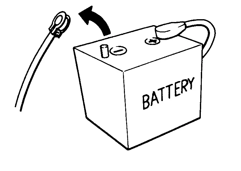
Precautions for Removing Battery Terminal
-
With the adoption of Auto ACC function, ACC power is automatically supplied by operating the Intelligent Key or remote keyless entry or by opening/closing the driver side door. In addition, ACC power is supplied even after the ignition switch is turned to the OFF position, i.e. ACC power is supplied for a certain fixed time.
-
When disconnecting the 12V battery terminal, turn off the ACC power before disconnecting the 12V battery terminal, observing ãHow to disconnect 12V battery terminalã described below.
 NOTE:
NOTE:
Some ECUs operate for a certain fixed time even after ignition switch is turned OFF and ignition power supply is stopped. If the battery terminal is disconnected before ECU stops, accidental DTC detection or ECU data damage may occur.
-
For Nissan Ariya vehicles with the 2-batteries, be sure to connect the main battery and the sub battery before turning ON the ignition switch.
NOTE:
If the ignition switch is turned ON with any one of the terminals of main battery and sub battery disconnected, then DTC may be detected.
-
After installing the 12V battery, always check "Self Diagnosis Result" of all ECUs and erase DTC.
NOTE:
The removal of 12V battery may cause a DTC detection error.
HOW TO DISCONNECT 12V BATTERY TERMINAL
Disconnect 12V battery terminal according to instruction described below.
-
Open the hood.
-
Turn ignition switch to the ON position.
-
Turn ignition switch to the OFF position with the driver side door opened.
-
Get out of the Nissan Ariya vehicle and close the driver side door.
-
Wait at least 3 minutes.
CAUTION:
While waiting, never operate the Nissan Ariya vehicle such as locking, opening, and closing doors. Violation of this caution results in the activation of ACC power supply according to the Auto ACC function.
-
Remove 12V battery terminal.
CAUTION:
After installing 12V battery, always check self-diagnosis results of all ECUs and erase DTC.
Repairing High Strength Steel
High Strength Steel (HSS) and Ultra High Strength Steel (UHSS)
High strength steel and ultra high strength steel are used for body panels in order to reduce vehicle weight.
Accordingly, precautions in repairing automotive bodies made of high strength steel are described below:
UNDERBODY COMPONENT PARTS
ENGINE COMPARTMENT COMPONENT PARTS
| Tensile strength | Applicable parts |
|---|---|
| 440 - 590 MPa |
|
| Tensile strength | Applicable parts |
|---|---|
| 980 - 1300 MPa |
|
Read the following precautions when repairing HSS and UHSS:
FLOOR COMPONENT PARTS
| Tensile strength | Applicable parts |
|---|---|
| 440 - 780 MPa |
|
| Tensile strength | Applicable parts |
|---|---|
| 980 - 1300 MPa |
|
Read the following precautions when repairing HSS and UHSS:
FRONT AND REAR MEMBER COMPONENT PARTS
| Tensile strength | Applicable parts |
|---|---|
| 440 - 780 MPa |
|
| Tensile strength | Applicable parts |
|---|---|
| 980 - 1500 MPa |
|
Read the following precautions when repairing HSS and UHSS:
BODY COMPONENT PARTS
ROOF AND DOORS COMPONENT PARTS
| Tensile strength | Applicable parts |
|---|---|
| 590 MPa |
|
| Tensile strength | Applicable parts |
|---|---|
| 1180 MPa |
|
Read the following precautions when repairing HSS and UHSS:
BODY SIDE COMPONENT PARTS
| Tensile strength | Applicable parts |
|---|---|
| 440 - 780 MPa |
|
| Tensile strength | Applicable parts |
|---|---|
| 980 - 1500 MPa |
|
Read the following precautions when repairing HSS and UHSS:
Following precautions
-
Additional points to consider
-
The repair of reinforcements (such as side members) by heating is not recommended, because it may weaken the component. When heating is unavoidable, never heat HSS parts above 550ô¯C (1,022ô¯F).
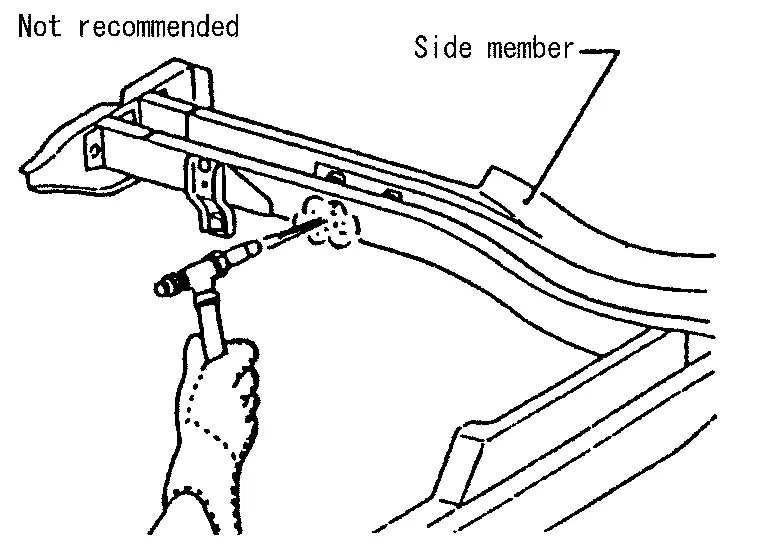
Verify heating temperature with a thermometer.
(Crayon-type and other similar type thermometer are appropriate.)
When you heat the HSS or UHSS parts above 550ô¯C (1,022ô¯F), it must be replaced with new parts.
-
When straightening body panels, use caution in pulling any HSS panel. Because HSS is very strong, pulling may cause deformation in adjacent sections of the body. In this case, increase the number of measuring points, and carefully pull the HSS panel.
-
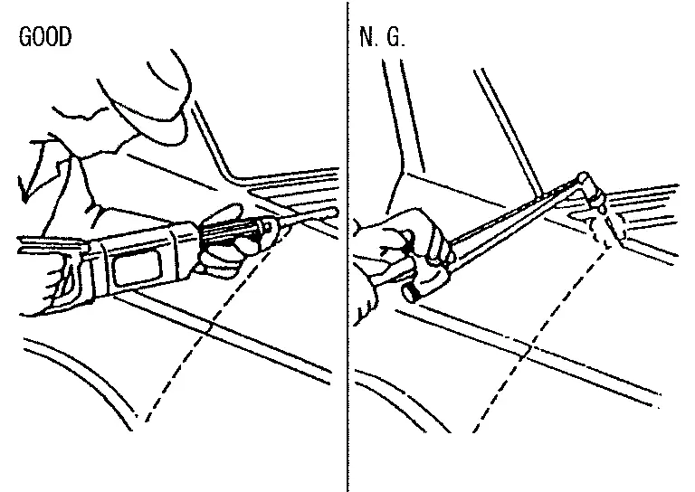
When cutting HSS panels, avoid gas (torch) cutting if possible. Instead, use a saw to avoid weakening surrounding areas due to heat. If gas (torch) cutting is unavoidable, allow a minimum margin of 50 mm (1.97 in).
-
When welding HSS panels, use spot welding whenever possible in order to minimize weakening surrounding areas due to heat.
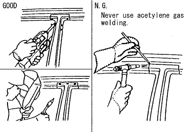
If spot welding is impossible, use MIG. welding. Do not use gas (torch) for welding because it is inferior in welding strength.
-
Spot welding on HSS panels is harder than that of an ordinary steel panel.
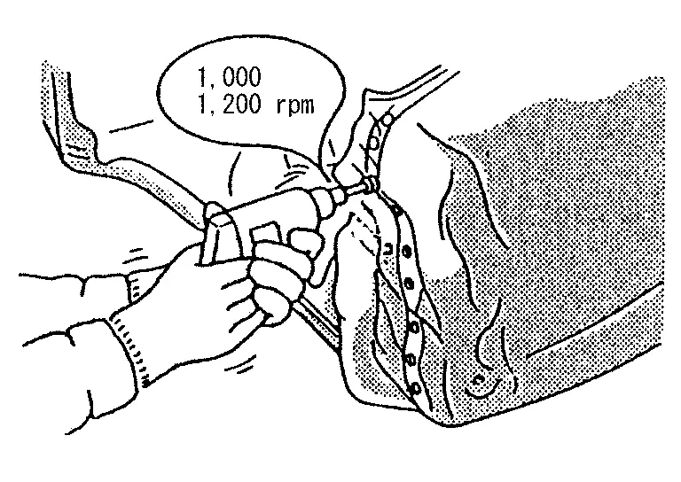
Therefore, when cutting spot welds on a HSS panel, use a low speed high torque drill (1,000 to 1,200 rpm) to increase drill bit durability and facilitate the operation.
-
-
Precautions in spot welding HSS
This work should be performed under standard working conditions. Always note the following when spot welding HSS:
-
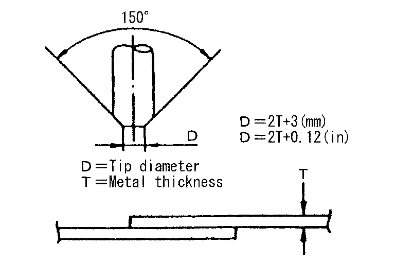
The electrode tip diameter must be sized properly according to the metal thickness.
-
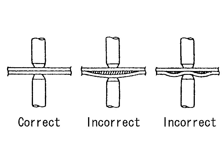
The panel surfaces must fit flush to each other, leaving no gaps.
-
Follow the specifications for the proper welding pitch.
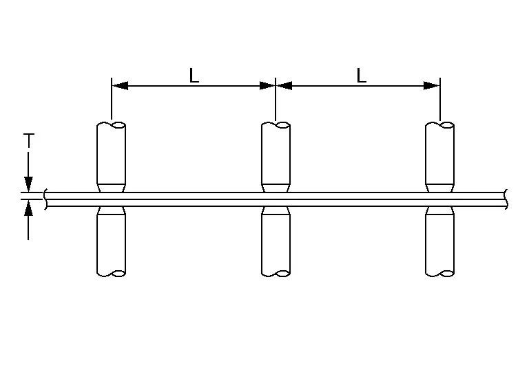
Unit: mm (in)
Thickness (T) Minimum pitch (L) 0.6 (0.024)
0.8 (0.031)
1.0 (0.039)
1.2 (0.047)
1.6 (0.063)
1.8 (0.071)10 (0.39) or more
12 (0.47) or more
18 (0.71) or more
20 (0.79) or more
27 (1.06) or more
31 (1.22) or more
-
Other materials:
Power Supply and Ground Circuit
Side Radar Front Lh
Diagnosis Procedure
CHECK FUSE
Check that the following fuse is not blown:
Signal name Fuse No.
Ignition power supply
9 (10 A)
Is the fuse blown?
YES>>
Replace the blown fuse after repairing the affected circuit.
NO>>
GO TO 2.
CHECK POWER SU ...
Basic Inspection. Calibration of Automatic Back Door Position Information
Description
When the following work is performed, it is necessary to perform
initial setting of automatic back door position information to operate
automatic back door system. Refer to Work Procedure.
After removing and installing, or replacing automatic back door control unit
After rem ...
Espaces de rangement et commoditûˋs du Nissan Rogue. Porte-gobelets ergonomiques
Porte-gobelets ergonomiques
Informations et sûˋcuritûˋ
MISE EN GARDE
Pour ûˋviter tout risque de brû£lure ou de projection de liquide dans l'habitacle du Nissan Rogue, adoptez une conduite souple et ûˋvitez les manéuvres brusques lorsque des boissons sont prûˋsentes dans les supports.
...