Nissan Rogue (T33) 2021-Present Service Manual: B2e08-01 Microphone
DTC Description
DTC DETECTION LOGIC
| DTC No. |
CONSULT screen terms (Trouble diagnosis content) | DTC detection condition | ||
|---|---|---|---|---|
| B2E08ŌĆō01 |
Microphone (Microphone) |
1 | Diagnosis condition | When ignition switch is ON. |
| Signal (terminal) | Microphone signal | |||
| Threshold | 7.2 V or more | |||
| Diagnosis delay time | 1 second or more | |||
| 2 | Diagnosis condition | When ignition switch is ON. | ||
| Signal (terminal) | Microphone signal | |||
| Threshold | 0.2 V or less | |||
| Diagnosis delay time | 1 second or more | |||
POSSIBLE CAUSE
-
Microphone signal circuit short to power supply
-
Microphone signal circuit short to ground
-
Microphone
FAIL-SAFE
Microphone does not operate
DTC CONFIRMATION PROCEDURE
PERFORM DTC CONFIRMATION PROCEDURE
 With CONSULT
-
Turn ignition switch ON.
-
Turn ignition switch OFF and wait at least 30 seconds.
-
Turn ignition switch ON and wait at least 30 seconds or more.
-
Select ŌĆ£Self Diagnostic ResultŌĆØ mode of ŌĆ£IVCŌĆØ using CONSULT.
-
Check DTC.
Is DTC B2E08-01 detected?
YES>>Refer to Diagnosis Procedure.
NO-1>>To check malfunction symptom before repair: Refer to Intermittent Incident.
NO-2>>Confirmation after repair: INSPECTION END
Diagnosis Procedure
CHECK MICROPHONE SIGNAL CIRCUIT AND MICROPHONE POWER SUPPLY CIRCUIT CONTINUITY
-
Turn ignition switch OFF.
-
Disconnect TCU connector and microphone connector.
-
Check continuity between TCU connector and microphone connector.
TCU Microphone Continuity Connector Terminal Connector Terminal M35 17 R8 8 Existed 18 3 -
Check the continuity between TCU connector and ground.
TCU Ground Continuity Connector Terminal M35 18 Not existed 17
Is the inspection result normal?
YES>>GO TO 2.
NO>>Repair or replace harness or connectors.
CHECK MICROPHONE POWER SUPPLY VOLTAGE
-
Connect TCU connector and microphone connector.
-
Turn ignition switch ON.
-
Check voltage between TCU connector and ground.
(+) (ŌłÆ) Voltage
(Approx.)TCU Connector Terminal M35 18 Ground 4.72 V
Is the inspection result normal?
YES>>GO TO 3.
NO>>Replace TCU. Refer to Removal & Installation.
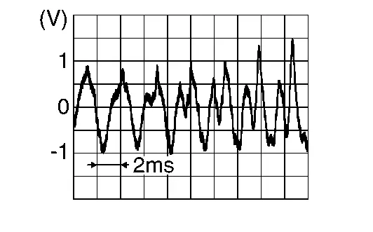
CHECK MICROPHONE SIGNAL
Check signal between TCU connector and ground.
| (+) | (ŌłÆ) | Condition | Reference value | |
|---|---|---|---|---|
| TCU | ||||
| Connector | Terminal | |||
| M35 | 17 | Ground | Speak into microphone. |
|
Is the inspection result normal?
YES>>Replace TCU.Refer to Removal & Installation.
NO>>Replace microphone.Refer to Removal and Installation.
Other materials:
Hill Start Assist system
WARNING
Never rely solely on the Hill Start Assist system to keep the Nissan Rogue from rolling backward on a hill. Always remain attentive, apply the brake pedal when stopped on steep inclines, and use extra caution on icy or muddy slopes. Failure to prevent rollback could result in loss of contr ...
Drivetrain Can Communication 2 Circuit
Diagnosis Procedure
CHECK NETWORK DIAGNOSIS
Check the "Network diagnosis" results from CONSULT to see that the diagnostic CAN communication circuit have no malfunction.
Are the diagnostic CAN communication circuit normal?
YES>>
GO TO 2.
NO>>
Check and repair diagnostic CAN commu ...
P2123 App Sensor
DTC Description
DTC DETECTION LOGIC DTC
CONSULT screen terms
(Trouble diagnosis content)
DTC detection condition
P2123
00
APP SEN 1/CIRC
(Throttle/Pedal position sensor/switch D circuit high)
Diagnosis condition
Engine running at idle
Signal (terminal)
Accelerator ...