Nissan Rogue (T33) 2021-Present Service Manual: Removal and Installation :: Front Disc Brake
Brake Pad
Exploded View
WITHOUT ProPILOT Assist 2.1
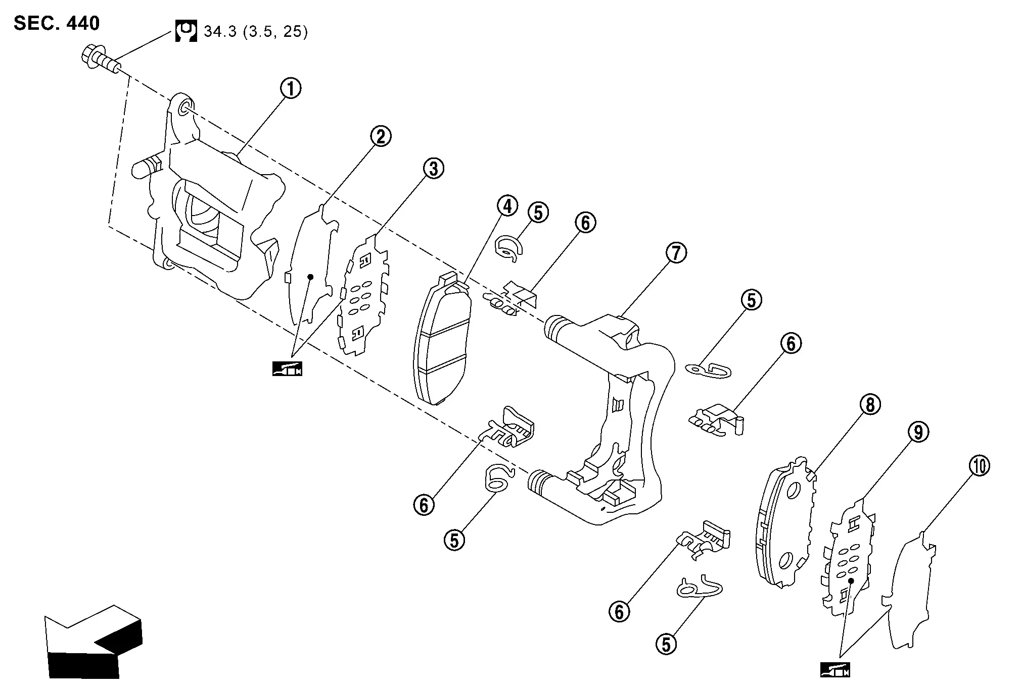
 |
Cylinder body |  |
Inner shim cover |  |
Inner shim |
 |
Inner pad (with pad wear sensor) |  |
Return spring |  |
Pad retainer |
 |
Torque member |  |
Outer pad |  |
Outer shim |
 |
Outer shim cover | ||||
| : Nissan Ariya Vehicle front | |||||
 |
: N·m (kg-m, ft-lb) | ||||
 |
: Apply MOLYKOTE® AS 880N or silicone-based grease. | ||||
Molykote is a registered trademark of Dow Corning Corporation.
WITH ProPILOT Assist 2.1
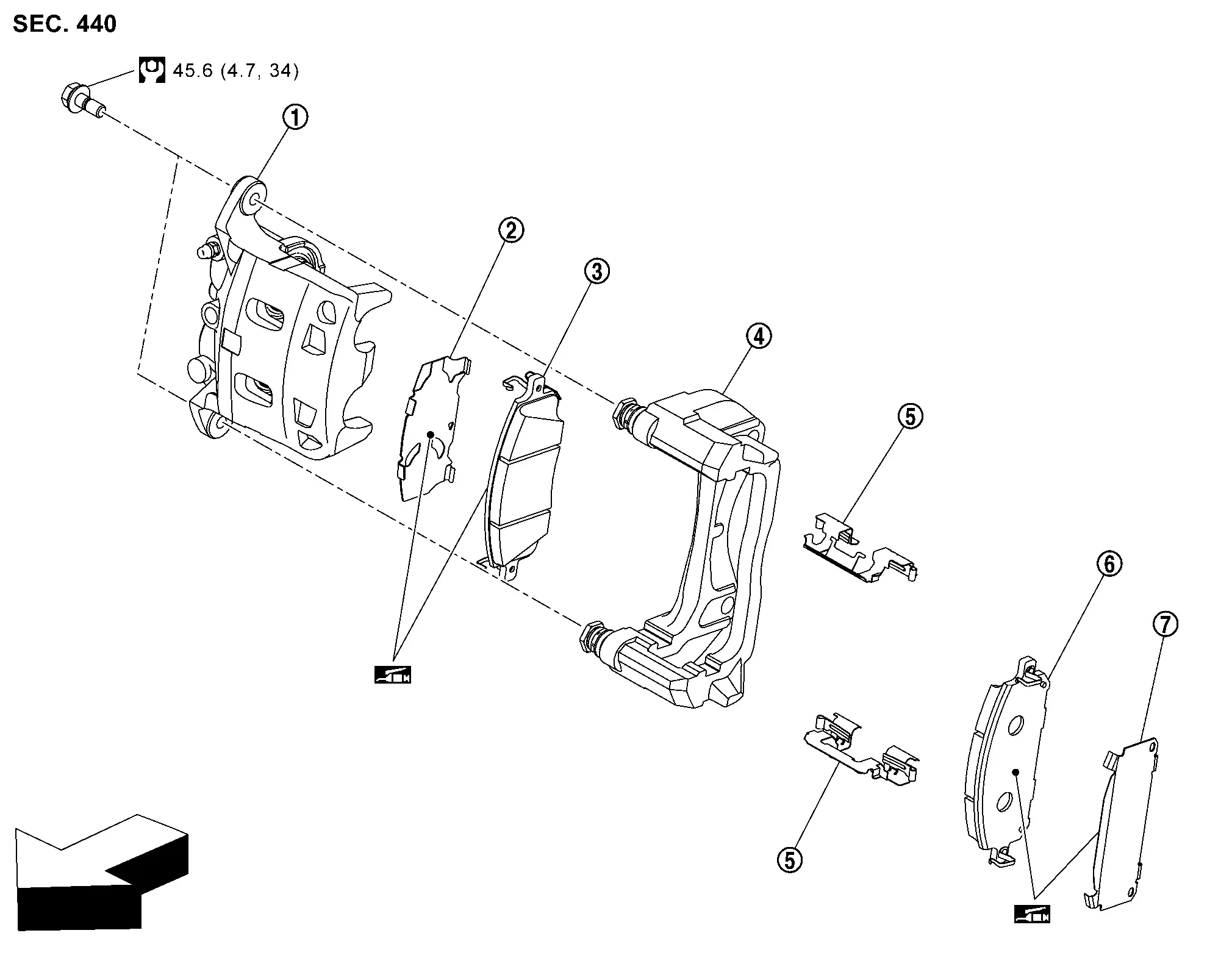
|
Cylinder body | |
Inner shim | |
Inner pad (with pad wear sensor) |
|
Torque member | |
Pad retainer | |
Outer pad (with pad wear sensor) |
|
Outer shim | ||||
 |
: Nissan Ariya Vehicle front | ||||
|
: N·m (kg-m, ft-lb) | ||||
|
: Nissan disc brake shim grease | ||||
Removal and Installation
WITHOUT ProPILOT Assist 2.1
REMOVAL
WARNING:
Since dust covering the front and rear brakes has an affect on human body, the dust must be removed with a dust collector. Never splatter the dust with an air blow gun.
CAUTION:
-
Never depress the brake pedal while removing the brake pads because the piston may pop out.
-
If the brake fluid or grease adheres to the brake caliper assembly and disc rotor, quickly wipe it off.
Remove tires with power tool.
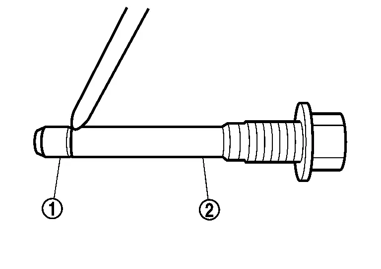
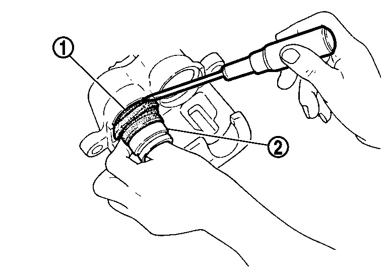
Remove lower sliding pin bolt.
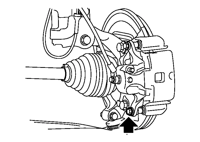
Suspend the cylinder body with suitable wire so that the brake hose will not stretch.
Remove the brake pads, shims, shim covers and pad retainer (as a set with pad return spring) from the torque member .
CAUTION:
-
Remove pad retainer together with pad return springs.
-
Never deform the pad return springs and pad retainer when removing the pad retainer from the torque member.
-
Never damage the piston boots.
-
Never drop the brake pads, shims and shim covers.
-
Remember each position of the removed brake pads.
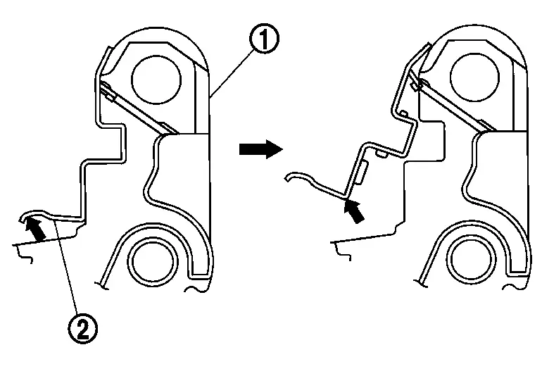
Remove the pad return springs from the pad retainer .
| : Disc rotor side |
CAUTION:
Never deform the pad return springs when removing the pad return springs from the pad retainer.
Perform inspection after removal. Refer to Inspection.
INSTALLATION
WARNING:
Since dust covering the front and rear brakes has an affect on human body, the dust must be removed with a dust collector. Never splatter the dust with an air blow gun.
CAUTION:
-
Never depress the brake pedal while removing the brake pads because the piston may pop out.
-
If the brake fluid or grease adheres to the brake caliper assembly and disc rotor, quickly wipe it off.
Install the pad return springs to pad retainer if the pad return springs has been removed.
| : Disc rotor side |
CAUTION:
Never deform the pad return springs.
Install the pad retainer (upper side with pad return spring) to torque member if the pad retainers has been removed.
CAUTION:
-
Securely assemble the pad retainers so that it will not be lifted up from the torque member.
-
Never deform the pad retainers and pad return springs.
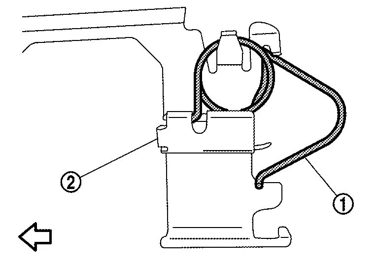
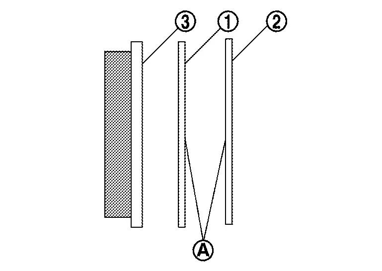
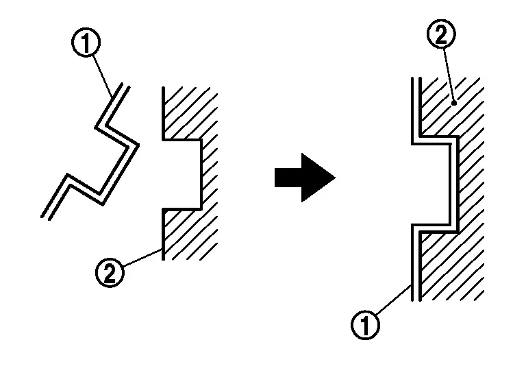
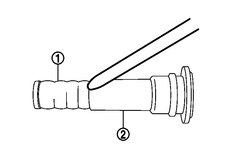
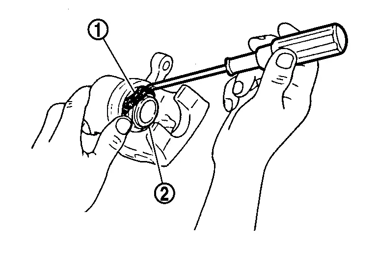
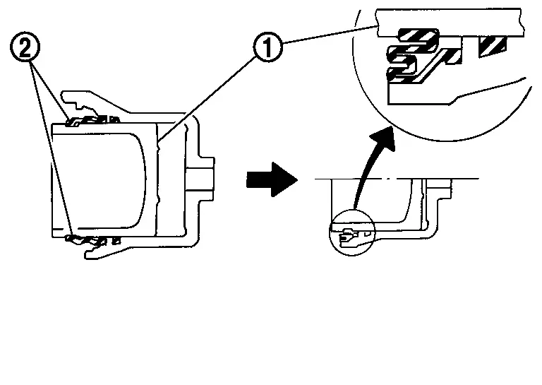
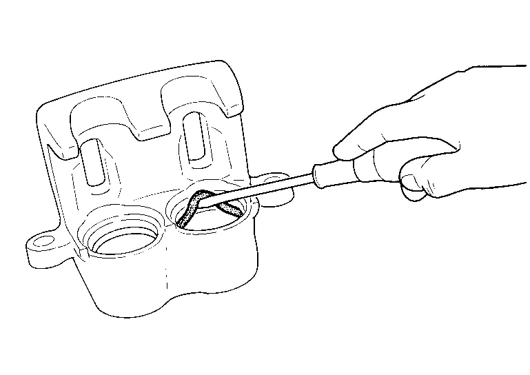
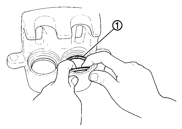
Apply MOLYKOTE® TE7439 or silicone-based grease to the matching faces  between the shim and the shim cover , and install the shim and the shim covers to the brake pad .
CAUTION:
Always replace the shims and shim covers when replacing the brake pad.
Molykote is a registered trademark of Dow Corning Corporation.
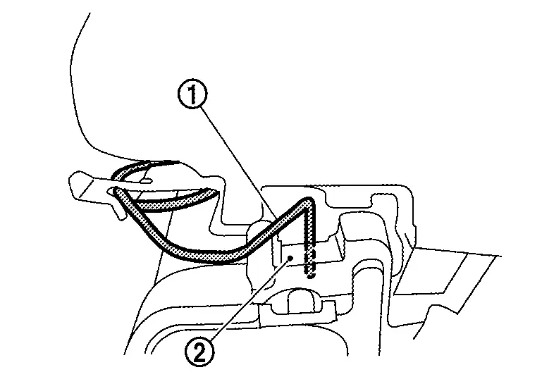
Install the brake pads to the torque member.
CAUTION:
Both inner and outer pads have a pad return system. Securely push the pad return spring into the disc rotor side of brake pad .
Install cylinder body to torque member.
CAUTION:
-
Never damage the piston boot.
-
When replacing brake pad with new one, check a brake fluid level in the reservoir tank because brake fluid returns to reservoir tank when pressing piston in.
 NOTE:
NOTE:
Use a disc brake piston tool to easily press piston.
Install the lower sliding pin bolt and tighten it to the specified torque.
Depress the brake pedal several times to check that no drag feel is present for the front disc brake. Refer to Inspection.
Install tires. Refer to Removal & Installation.
WITH ProPILOT Assist 2.1
REMOVAL
WARNING:
Remove dust covering brake caliper assembly and brake pad with a dust collector. Never splatter the dust with an air blow gun.
CAUTION:
-
Never depress the brake pedal while removing the brake pads because the piston may pop out.
-
If the brake fluid or grease adheres to the brake caliper assembly and disc rotor, quickly wipe it off.
Remove tires. Refer to Removal & Installation.
Remove sliding pin bolt (lower side).
Hang cylinder body with suitable wire not to stretch brake hose.
Remove brake pads, shims, and pad retainer from torque member.
CAUTION:
-
When removing pad retainer
from torque member , never deform pad retainer.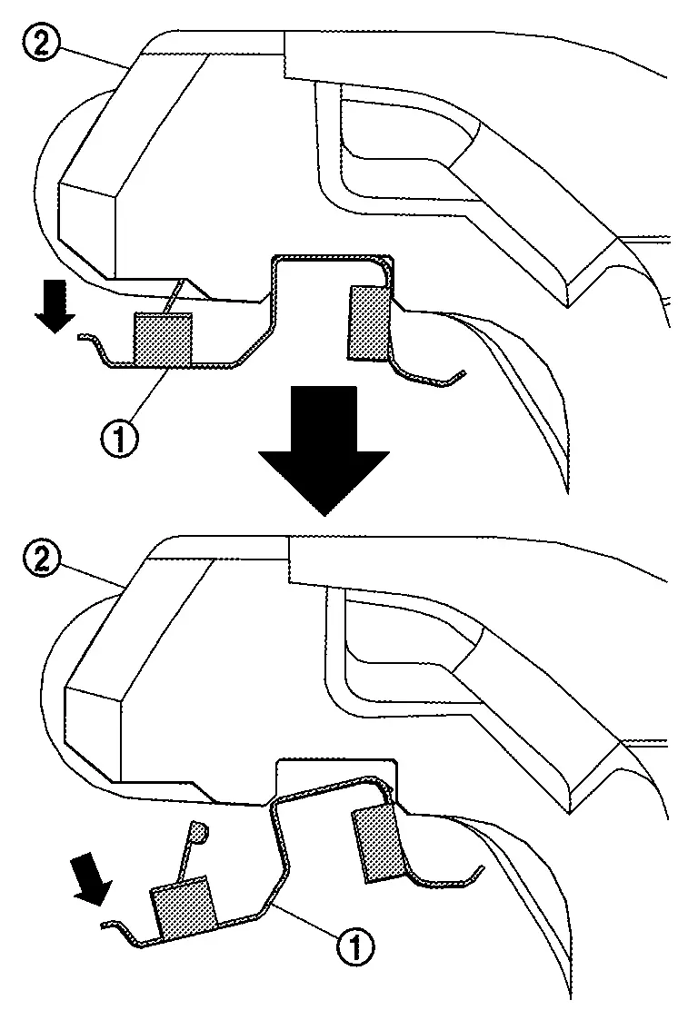
-
Never damage piston boots.
-
Never drop brake pads, and shims.
-
Distinguish each position of removed brake pads.
Perform inspection after removal. Refer to Inspection.
INSTALLATION
WARNING:
Remove dust covering brake caliper assembly and brake pad with a dust collector. Never splatter the dust with an air blow gun.
CAUTION:
-
Never depress brake pedal while removing brake pads because the piston may pop out.
-
If the brake fluid or grease adheres to disc rotor and cylinder body, quickly wipe it off.
Install pad retainers to torque members if pad retainers are removed before.
CAUTION:
-
Securely assemble pad retainers not to be lifted up from torque member.
-
Never deform pad retainers.
Apply Nissan disc brake shim grease to the matching surfaces between brake pad and shim cover , and install shim covers to brake pad.
CAUTION:
When replacing the brake pad always replace the shims and shim covers as a set.
Install brake pads to torque member.
CAUTION:
Never damage pad retainer.
Install cylinder body to torque member.
CAUTION:
-
Never damage piston boot.
-
When installing cylinder body, check brake fluid level in reservoir tank because brake fluid returns to reservoir tank of brake master cylinder assembly by pressing piston in.
NOTE:
Use disc brake piston tool (commercial tool) to press piston easily.
Install slide pin bolt (lower side) and tighten to the specified torque.
Perform inspection after installation. Refer to Inspection.
Install tires. Refer to Removal & Installation.
Inspection
INSPECTION AFTER REMOVAL
-
Replace the shims and shim covers if rust is excessively attached.
-
Eliminate rust on the pad return spring, pad retainers and the torque member. Replace them if rust is excessively attached.
INSPECTION AFTER INSTALLATION
-
Check a drag of front disc brake. If any drag is found, follow the procedure described below.
Remove brake pads. Refer to Removal and Installation.
Press the pistons. Refer to Removal and Installation.
Install brake pads. Refer to Removal and Installation.
Depress the brake pedal several times.
Check a drag of front disc brake again. If any drag is found, disassemble the cylinder body and replace if necessary. Refer to Disassembly and Assembly.
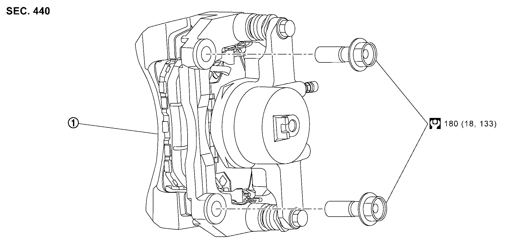
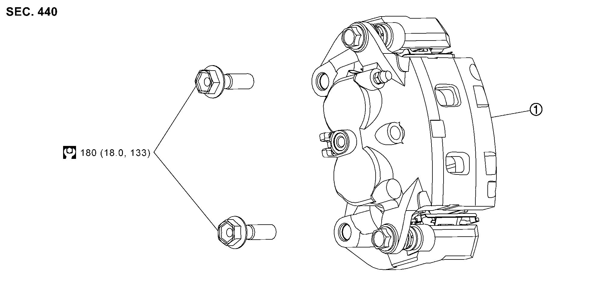
Brake Caliper Assembly
Exploded View
WITHOUT ProPILOT Assist 2.1
REMOVAL
|
Brake caliper assembly | ||||
|
: N·m (kg-m, ft-lb) |
DISASSEMBLY
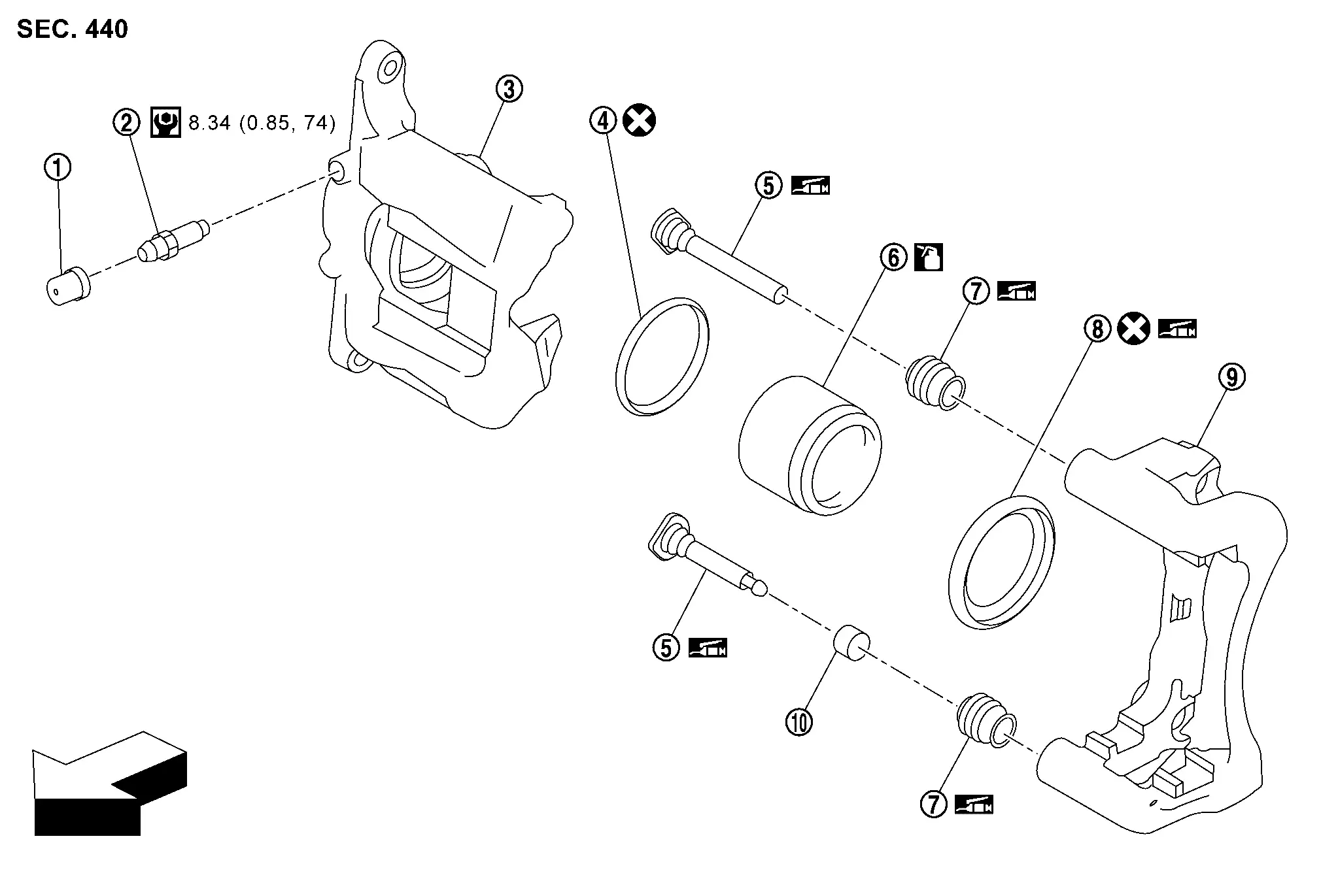
|
Cap | |
Bleeder valve | |
Cylinder body |
|
Piston seal | |
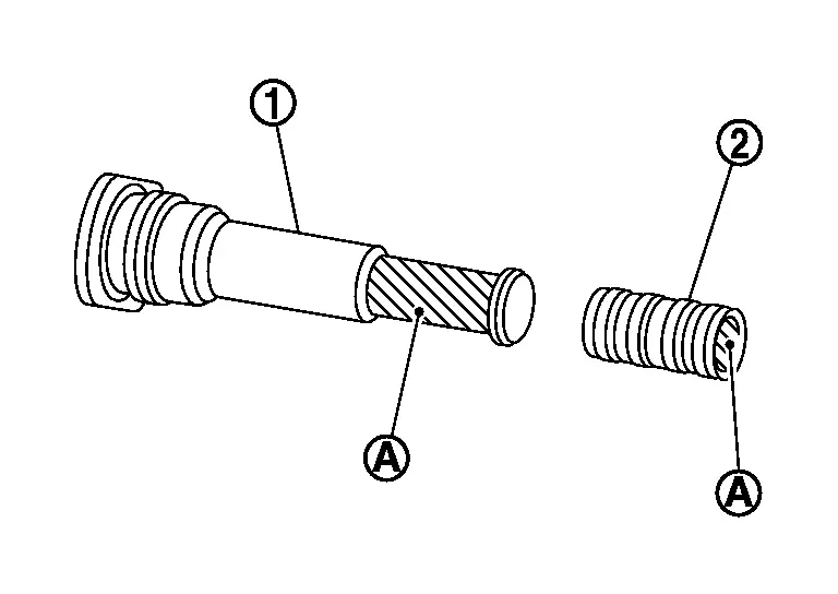
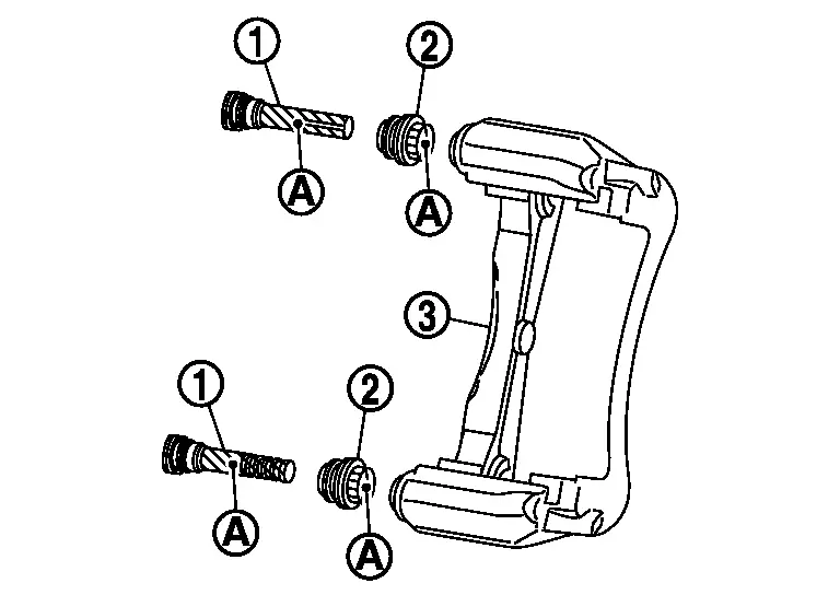
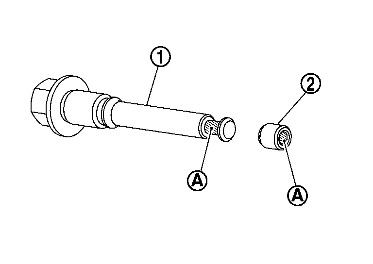
Sliding pin | |
Piston |
|
Sliding pin boot | |
Piston boot | |
Torque member |
|
Bushing | ||||
| : Nissan Ariya Vehicle front | |||||
 |
: N·m (kg-m, in-lb) | ||||
 |
: Apply brake fluid. | ||||
|
: Apply rubber grease. | ||||
 |
: Always replace after every disassembly. | ||||
WITH ProPILOT Assist 2.1
REMOVAL
|
Brake caliper assembly | ||||
|
: N·m (kg-m, ft-lb) | ||||
DISASSEMBLY
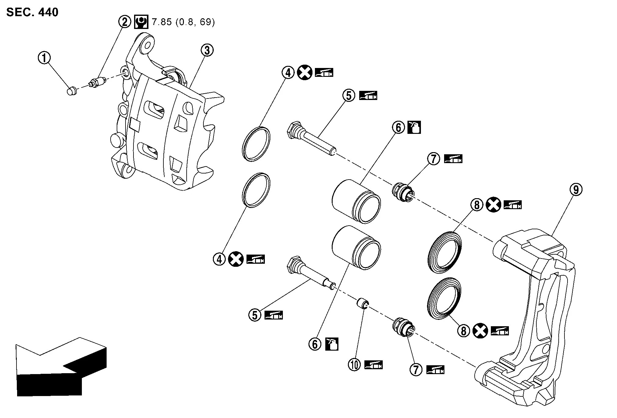
|
Cap | |
Bleeder valve | |
Cylinder body |
|
Piston seal | |
Sliding pin | |
Piston |
|
Sliding pin boot | |
Piston boot | |
Torque member |
|
Bushing | ||||
|
: Nissan Ariya Vehicle front | ||||
|
: N·m (kg-m, in-lb) | ||||
|
: NISSAN rubber grease. | ||||
|
: NISSAN brake fluid No.2500 | ||||
|
: Always replace after every disassembly. | ||||
Removal and Installation
REMOVAL
WARNING:
Since dust covering the front and rear brakes has an affect on human body, the dust must be removed with a dust collector. Never splatter the dust with an air blow gun.
CAUTION:
-
Never spill or splash brake fluid on painted surfaces. Brake fluid may seriously damage paint. Wipe it off immediately and wash with water if it gets on a painted surface. However avoid washing brake components with water.
-
Never depress the brake pedal while removing the brake pads because the piston may pop out.
-
If the brake fluid or grease adheres to the brake caliper assembly and disc rotor, quickly wipe it off.
Remove tires with power tool.
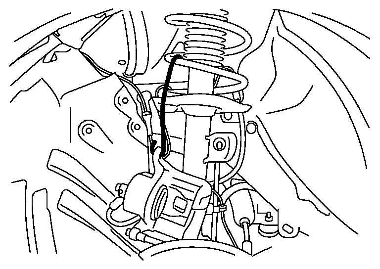
Fix the disc rotor using wheel nuts.
Drain brake fluid. Refer to Draining.
Remove union bolt and copper washer, and separate brake hose from brake caliper assembly. Refer to Removal and Installation.
Remove torque member mounting bolts, and remove brake caliper assembly.
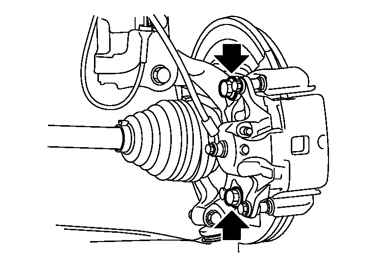
CAUTION:
Never drop brake pad and brake caliper assembly.
Remove disc rotor.
-
For 2WD: Refer to Removal and Installation.
-
For AWD: Refer to Removal and Installation.
INSTALLATION
WARNING:
Since dust covering the front and rear brakes has an affect on human body, the dust must be removed with a dust collector. Never splatter the dust with an air blow gun.
CAUTION:
-
Never spill or splash brake fluid on painted surfaces. Brake fluid may seriously damage paint. Wipe it off immediately and wash with water if it gets on a painted surface. However avoid washing brake components with water.
-
Never depress the brake pedal while removing the brake pads because the piston may pop out.
-
If the brake fluid or grease adheres to the brake caliper assembly and disc rotor, quickly wipe it off.
-
Never allow foreign matter (e.g.dust) and oils other than brake fluid to enter the reservoir tank.
Install disc rotor.
-
For 2WD: Refer to Removal and Installation.
-
For AWD: Refer to Removal and Installation.
Install the brake caliper assembly to the steering knuckle and tighten the torque member mounting bolts to the specified torque.
CAUTION:
Never spill or splash any grease and moisture on the brake caliper assembly mounting face, threads, mounting bolts and washers. Wipe out any grease and moisture.
Install brake hose and copper washers to brake caliper assembly. Refer to Removal and Installation.
CAUTION:
Never reuse copper washer.
Refill with new brake fluid and perform the air bleeding. Refer to Bleeding Brake System.
CAUTION:
-
Never reuse brake fluid.
-
Never spill or splash brake fluid on the surface of disc rotor.
Check a drag of front disc brake. If any drag is found, refer to Inspection.
Install tires. Refer to Removal & Installation.
Perform inspection after installation. Refer to Inspection.
Disassembly and Assembly
WITHOUT ProPILOT Assist 2.1
DISASSEMBLY
NOTE:
Never remove the torque member, brake pad and pad retainers when disassembling and assembling the cylinder body.
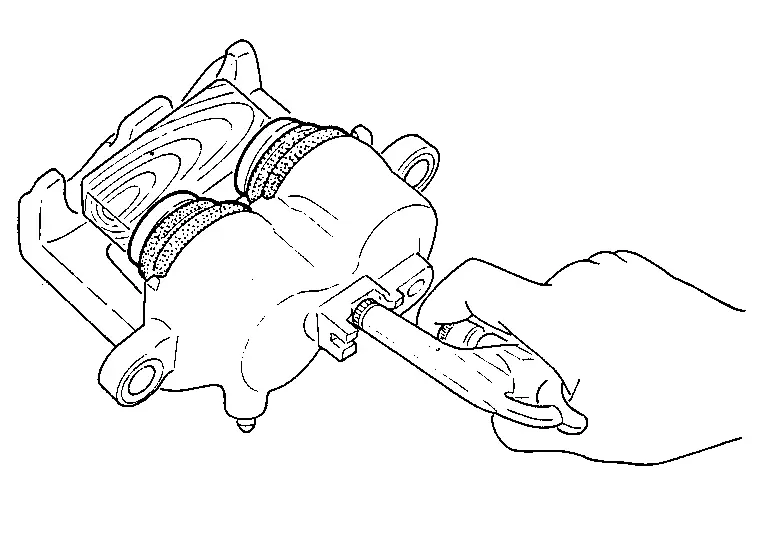
Remove the sliding pin bolt, and remove the cylinder body from the torque member. Refer to Removal and Installation.
CAUTION:
Fix the brake pad at suitable tape so that the brake pad will not drop.
Remove sliding pins and sliding pin boots from torque member.
Remove bushing from sliding pin .
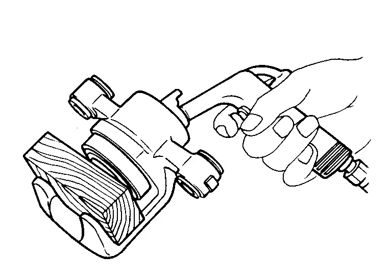
Place a wooden block as shown in the figure, and blow air from union bolt mounting hole to remove pistons and piston boots.
CAUTION:
Never get fingers caught in the pistons.
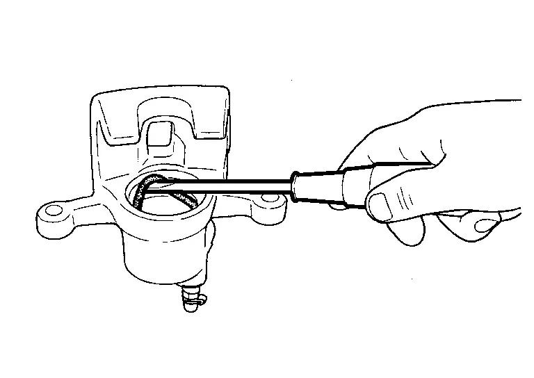
Remove piston seals from cylinder body using seal pick tool.
CAUTION:
Be careful not to damage a cylinder inner wall.
Remove bleeder valve and cap.
Perform inspection after disassembly. Refer to Inspection.
ASSEMBLY
Install bleeder valve and cap.
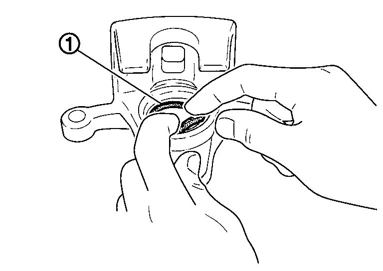
Apply new brake fluid to piston seals , and install them to cylinder body.
CAUTION:
Never reuse piston seals.
Apply rubber grease to piston boots . Cover the piston end with piston boot, and then install cylinder side lip on piston boot securely into a groove on cylinder body.
CAUTION:
Never reuse piston boots.
Apply new brake fluid to pistons . Push piston into cylinder body by hand and push piston boot piston-side lip into the piston groove.
CAUTION:
Press the pistons evenly and vary the pressing point to prevent cylinder inner wall from being rubbed.
Apply rubber grease to mating faces between sliding pin and bushing , and install bushing to sliding pin.
Apply rubber grease to mating faces between sliding pins and sliding pin boots , and install sliding pins and sliding pin boots to torque member .
Install the cylinder body to tighten sliding pin bolts to the specified torque.
WITH ProPILOT Assist 2.1
DISASSEMBLY
CAUTION:
Never drop parts.
NOTE:
When disassembling, torque member, brake pad, and pad retainer are not required to remove. Refer to Removal and Installation.
Remove sliding pin bolts and then remove cylinder body from torque member.
CAUTION:
Never drop brake pad by fixing it with suitable tape.
Remove sliding pin boots from torque member.
Remove bushing from sliding pin .
Place a wooden block as shown in the figure, and blow air into union bolt mounting hole to remove pistons and piston boots.
CAUTION:
Never get fingers caught in the pistons.
Remove piston seals from cylinder body using seal pick tool.
CAUTION:
Be careful not to damage a cylinder inner wall.
Remove bleeder valve and cap.
Perform inspection after disassembly. Refer to Inspection.
ASSEMBLY
CAUTION:
Never drop parts.
Install bleeder valve and cap.
Apply Nissan rubber grease to piston seals , and install them to cylinder body.
CAUTION:
Never reuse piston seals.
Apply Nissan rubber grease to piston boots . Cover piston end with piston boot, and then install cylinder side lip of piston boot securely into groove on cylinder body.
CAUTION:
Never reuse piston boots.
Apply new brake fluid to pistons . Push piston into cylinder body and then install piston-side lip of piston boot into the piston groove.
CAUTION:
Press the pistons evenly and vary the pressing point to prevent cylinder inner wall from being rubbed.
Apply rubber grease to mating faces between sliding pin and bushing , and install bushing to sliding pin.
Apply rubber grease to mating faces between sliding pins and sliding pin boots , and install sliding pins and sliding pin boots to torque member .

Install cylinder body to torque member and tighten sliding pin bolts to the specified torque.
Inspection
INSPECTION AFTER DISASSEMBLY
Check the following items and replace if necessary.
Cylinder Body
Check the cylinder inner wall for rust, wear, cracks or damage.
CAUTION:
Always clean with new brake fluid. Never clean with mineral oil such as gasoline and light oil.
Torque Member
Check the torque member for rust, wear, cracks or damage.
Pistons
Check the surface of the piston for rust, wear, cracks or damage.
CAUTION:
A piston sliding surface is plated. Never polish with sandpaper.
Sliding Pin, Sliding Pin Boot and Bushing
Check the sliding pins, sliding pin boots and bushing for rust, wear, cracks or damage.
INSPECTION AFTER INSTALLATION
-
Check a drag of front disc brake. If any drag is found, follow the procedure described below.
Remove brake pads. Refer to Removal and Installation.
Press the pistons. Refer to Removal and Installation.
Install brake pads. Refer to Removal and Installation.
Depress the brake pedal several times.
Check a drag of front disc brake again. When any drag is found, disassemble the cylinder body and replace if necessary. Refer to Disassembly and Assembly.
Other materials:
System Description. Diagnosis System (bcm)
Common Item
CONSULT Function - COMMON ITEM
BCM
Refer to CONSULT Function (BCM - COMMON ITEM).
Theft Alm
CONSULT Function - THEFT ALM
BCM
Refer to CONSULT Function (BCM - THEFT ALM).
...
P2103 Throttle Control Motor Relay
DTC Description
DTC DETECTION LOGIC DTC
CONSULT screen terms
(Trouble diagnosis content)
DTC detection condition
P2103
00
ETC MOT PWR-B1
(Throttle actuator “A” control motor circuit high)
Diagnosis condition
Ignition switch ON
Signal (terminal)
Throttle contro ...
Ecu Diagnosis Information. Electrically-Driven Intelligent Brake Unit
DTC Index
DTC Display item Brake warning lamp Brake system warning lamp Refer to
B14E0-02
Wheel sensor
OFF
ON
DTC Description
B14E0-09
Wheel sensor
OFF
ON
DTC Description
B14E0-11
Wheel sensor
OFF
ON
DTC Description
B14E0-12
Wheel sensor ...