Nissan Rogue (T33) 2021-Present Service Manual: Kr15ddt :: Basic Inspection
Diagnosis and Repair Workflow
Work Flow
OVERALL SEQUENCE
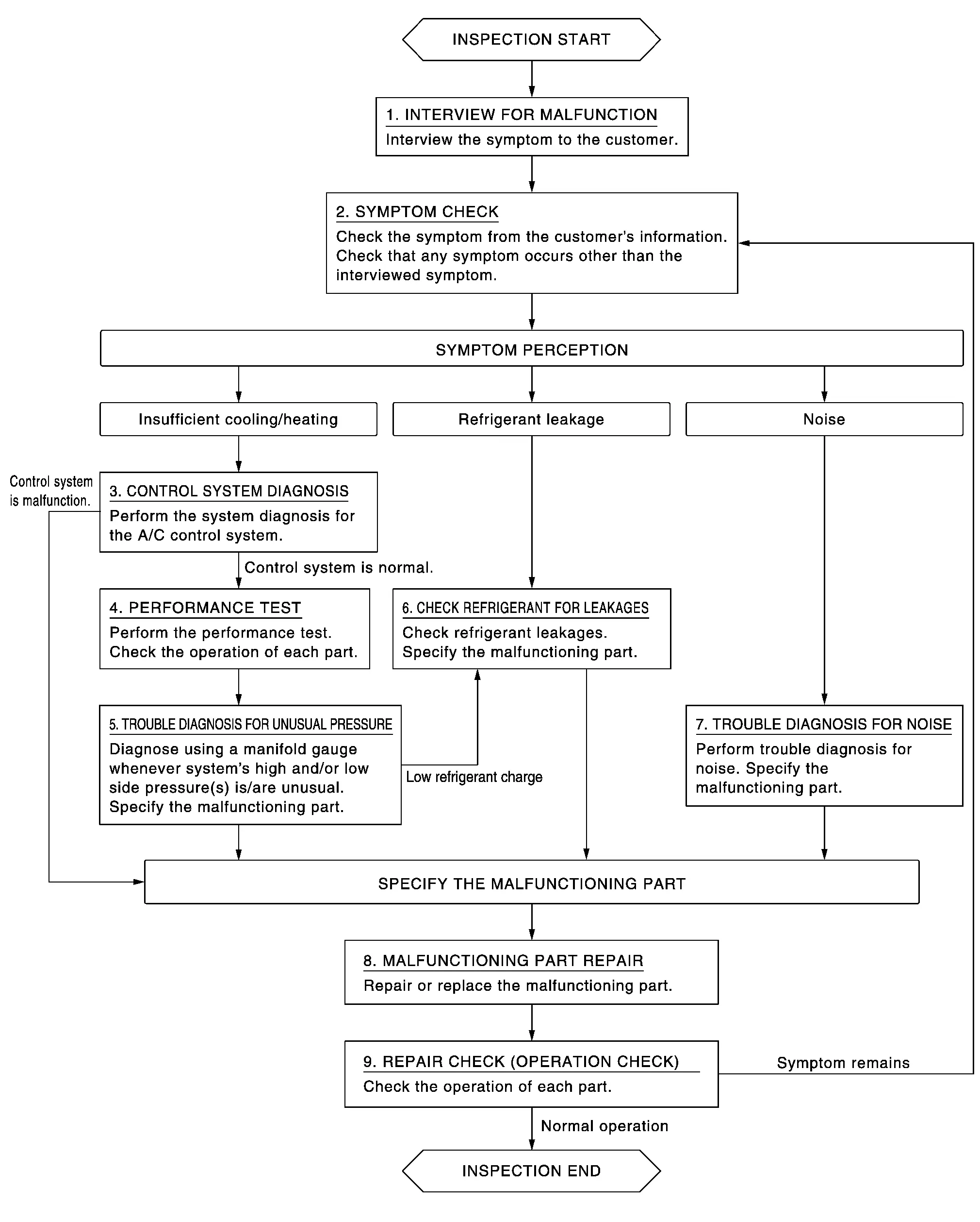
DETAILED FLOW
INTERVIEW FOR MALFUNCTION
Interview the symptom to the customer.
>>
GO TO 2.
SYMPTOM CHECK
Check the symptom from the customer's information. Check that any symptom occurs other than the interviewed symptom.
Insufficient cooling/heating>>
GO TO 3.
Refrigerant leakage>>GO TO 6.
Noise>>GO TO 7.
CONTROL SYSTEM DIAGNOSIS
Perform the system diagnosis for the A/C control system. Refer to Work Flow (AUTOMATIC AIR CONDITIONING) or Work Flow (MANUAL AIR CONDITIONING).
Is A/C control system normal?
YES>>GO TO 4.
NO>>GO TO 8.
PERFORMANCE TEST
Perform the performance test. Check the operation of each part. Refer to Inspection.
>>
GO TO 5.
TROUBLE DIAGNOSIS FOR UNUSUAL PRESSURE
Diagnose using a manifold gauge whenever system's high and/or low side pressure(s) is/are unusual. Specify the malfunctioning part. Refer to Symptom Table.
Low refrigerant charge>>
GO TO 6.
Except above>>GO TO 8.
CHECK REFRIGERANT FOR LEAKAGE
Check refrigerant for leakage. Specify the malfunctioning part. Refer to Leak Test.
>>
GO TO 8.
TROUBLE DIAGNOSIS FOR NOISE
Perform trouble diagnosis for noise. Specify the malfunctioning part. Refer to Symptom Table.
>>
GO TO 8.
MALFUNCTION PART REPAIR
Repair or replace the malfunctioning part.
>>
GO TO 9.
REPAIR CHECK (OPERATION CHECK)
Check the operation of each part.
Does it operate normally?
YES>>Inspection End.
NO>>GO TO 2.
Refrigerant
Description
CONNECTION OF SERVICE TOOLS AND EQUIPMENT
Be certain to follow the manufacturerŌĆÖs instructions for connecting to the machine.
Leak Test
CHECK REFRIGERANT LEAKAGE USING ELECTRICAL LEAK DETECTOR
WARNING:
Never check refrigerant leakage while the engine is running.
CAUTION:
Be careful of the following items so that inaccurate checks or misidentifications are avoided.
-
Never allow refrigerant vapor, shop chemical vapors, cigarette smoke, or others around the Nissan Ariya vehicle.
-
Always check refrigerant leakage in a low air flow environment so that refrigerant may not disperse when leakage occurs.
Stop the engine.
Connect recovery/recycling/recharging equipment or manifold gauge set to A/C service valve.
Check that A/C refrigerant pressure is 345 kPa (3.45 bar, 3.52 kg/cm2, 50 psi) or more when temperature is 16┬░C (61┬░F) or more. When pressure is lower than the specified value, recycle refrigerant completely and fill refrigerant to the specified level.
 NOTE:
NOTE:
Leakages may not be detected if A/C refrigerant pressure is 345 kPa (3.45 bar, 3.52 kg/cm2, 50 psi) or less when temperature is less than 16┬░C (61┬░F).
Clean area where refrigerant leakage check is performed, and check refrigerant leakage along all surfaces of pipe connections and A/C system components using electrical leak detector probe.
CAUTION:
-
Continue checking when a leakage is found. Always continue and complete checking along all pipe connections and A/C system components for additional leakage.
-
When a leakage is detected, clean leakage area using compressed air and check again.
-
When checking leakage of cooling unit inside, always clean inside of drain hose so that the probe surface may not be exposed to water or dirt.
NOTE:
-
Always check leakage starting from high-pressure side and continue to low-pressure side.
-
When checking leakage of cooling unit inside, operate blower fan motor for 15 minutes or more at the maximum fan speed while the engine is stopped, and then insert electrical leak detector probe into drain hose and hold for 10 minutes or more.
-
When disconnecting shut-off valve that is connected to A/C service valve, always evacuate remaining refrigerant so that misidentification can be avoided.
Repair or replace parts where refrigerant leakage is detected. (Leakage is detected but leakage area is unknown. GO TO 6.)
Start the engine and set A/C control in the following conditions.
-
A/C switch ON
-
Air flow: VENT (ventilation)
-
Intake door position: Recirculation
-
Temperature setting: Full cold
-
Fan (blower) speed: Maximum speed set
Run the engine at approximately 1,500 rpm for 2 minutes or more.
Stop the engine. Check again for refrigerant leakage. GO TO 4.
WARNING:
Be careful not to get burned when the engine is hot.
NOTE:
-
Start refrigerant leakage check immediately after the engine is stopped.
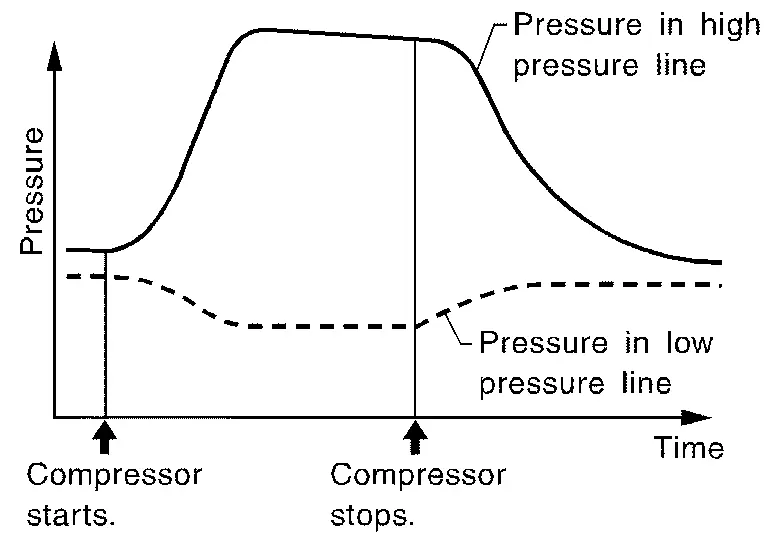
-
When refrigerant circulation is stopped, pressure on the low-pressure side rises gradually, and after this, pressure on the high-pressure side falls gradually.
-
The higher the pressure is, the easier it is to find the refrigerant leakage.
Recycle Refrigerant
WARNING:
-
Always use HFO-1234yf for A/C refrigerant. If CFC-12 or HFC-134a is accidentally charged, A/C compressor is damaged due to insufficient lubrication.
-
Always observe and follow precautions described on refrigerant container and service manual. Incorrect handling may result in an explosion of refrigerant container, frostbite, or the loss of eyesight.
-
Never breathe A/C refrigerant and lubricant vapor or mist. Exposure may irritate eyes, nose, or throat.
-
Never allow HFO-1234yf to be exposed to an open flame or others because it generates poisonous gas when in contact with high temperature objects. Keep workshop well ventilated.
-
Never place the refrigerant containers and recovery/recycling equipment in a place where the temperature exceeds 40┬░C (104┬░F).
-
Use a approved refrigerant recovery/recycling equipment (for HFO-1234yf).
Perform lubricant return operation. Refer to Perform Lubricant Return Operation. (If refrigerant or lubricant leakage is detected in a large amount, omit this step, and then GO TO 2.)
CAUTION:
Never perform lubricant return operation if a large amount of refrigerant or lubricant leakage is detected.
Check gauge pressure readings of recovery/recycling/recharging equipment. When remaining pressure exists, recycle refrigerant from high-pressure hose and low-pressure hose.
NOTE:
Follow manufacturer instructions for the handling or maintenance of the equipment. Never fill the equipment with non-specified refrigerant.
Remove A/C service valve cap from the Nissan Ariya vehicle.
Connect recovery/recycling/recharging equipment to A/C service valve.
Operate recovery/recycling/recharging equipment, and recycle refrigerant from the Nissan Ariya vehicle.
Evacuate air for 10 minutes or more to remove any remaining refrigerant integrated to compressor lubricant, etc.
Refrigerant recycle operation is complete.
Charge Refrigerant
WARNING:
-
Always use HFO-1234yf for A/C refrigerant. If CFC-12 or HFC-134a is accidentally charged, compressor is damaged due to insufficient lubrication.
-
Always observe and follow precautions described on refrigerant container. Incorrect handling may result in an explosion of refrigerant container, frostbite, or the loss of eyesight.
-
Never breathe A/C refrigerant and lubricant vapor or mist. Exposure my irritate eyes, nose, or throat.
-
Never allow HFO-1234yf to be exposed to an open flame or others because it generates poisonous gas when in contact with high temperature objects. Keep workshop well ventilated.
-
Never place the refrigerant containers and recovery/recycling equipment in a place where the temperature exceeds 40┬░C (104┬░F).
-
Use a approved refrigerant recovery/recycling equipment (for HFO-1234yf).
Connect recovery/recycling/recharging equipment to the A/C service valve.
Operate recovery/recycling/recharging equipment, and evacuate air from A/C system for 25 minutes or more.
CAUTION:
Evacuate air for 15 minutes or more if the parts are replaced.
Check the airtightness of A/C system for 25 minutes or more. If pressure raises more than the specified level, charge A/C system with approximately 200 g refrigerant and check that there is no refrigerant leakage. Refer to Leak Test.
CAUTION:
Check the airtightness for 15 minutes or more if the parts are replaced.
If parts other than compressor are replaced, fill compressor lubricant according to parts that are replaced.
Charge the specified amount of refrigerant to A/C system.
Check that A/C system operates normally.
Disconnect recovery/recycling/recharging equipment. (Collect the refrigerant from the high-pressure hose and low-pressure hose of recovery/recycling/recharging equipment.)
Install A/C service valve cap.
Refrigerant charge is complete.
Lubricant
Description
MAINTENANCE OF LUBRICANT LEVEL
The A/C compressor lubricant is circulating in the system together with the refrigerant. It is necessary to fill A/C compressor with lubricant when replacing A/C system parts or when a large amount of refrigerant leakage is detected. It is important to always maintain lubricant level within the specified level. Or otherwise, the following conditions may occur.
-
Insufficient lubricant amount: Stuck A/C compressor
-
Excessive lubricant amount: Insufficient cooling (caused by insufficient heat exchange)
| Name | : ND-OIL12 (PAG) |
Inspection
If a A/C compressor is malfunctioning (internal noise, insufficient cooling), check the A/C compressor oil.
COMPRESSOR OIL JUDGMENT
-
Remove the A/C compressor. Refer to Removal and Installation.
-
Sample a A/C compressor oil and judge on the figure.
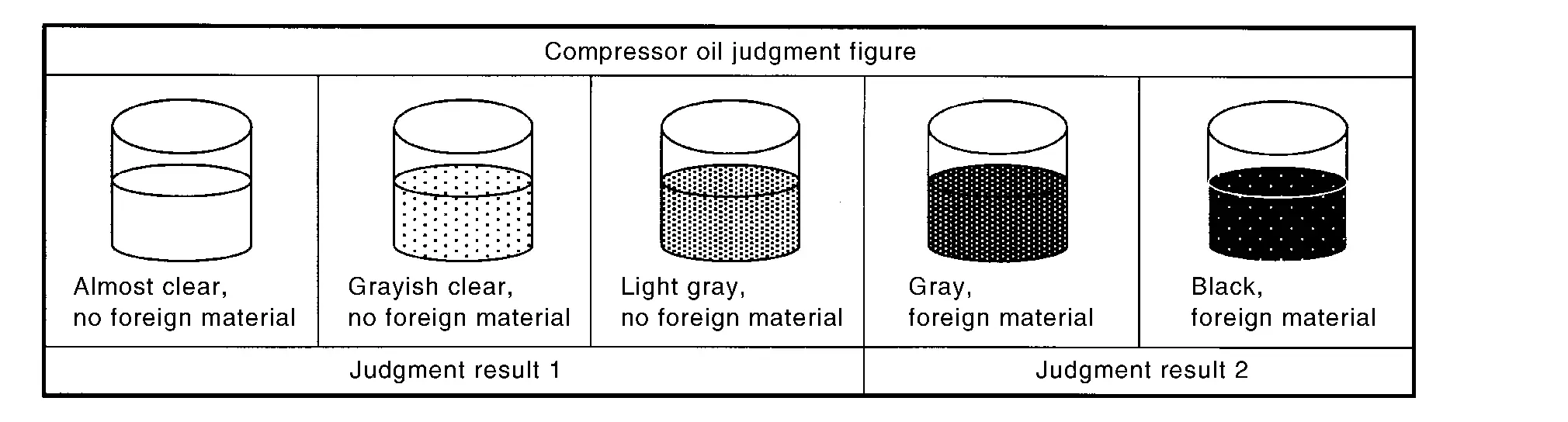
Judgement result 1
Replace A/C compressor only.
Judgement result 2
Replace compressor and condenser & liquid tank.
Perform Lubricant Return Operation
CAUTION:
If a large amount of refrigerant or lubricant leakage is detected, never perform lubricant return operation.
Start the engine and set to the following conditions.
-
Engine speed: Idling to 1,200 rpm
-
A/C switch: ON
-
Fan (blower) speed: Maximum speed set
-
Intake door position: Recirculation
-
Temperature setting: Full cold
Perform lubricant return operation for approximately 10 minutes.
Stop the engine.
Lubricant return operation is complete.
Lubricant Adjusting Procedure for Components Replacement Except A/C compressor
Fill with lubricant for the amount that is calculated according to the following conditions.
Example: Lubricant amount to be added when replacing evaporator and condenser & liquid tank [m (Imp fl oz)] = 45 (1.6) + 15 (0.5) + ╬▒
| Conditions |
Lubricant amount to be added to A/C system m (Imp fl oz) | |
|---|---|---|
| Replace evaporator | 35 (1.2) | |
| Replace condenser & liquid tank | 20 (0.7) | |
| Refrigerant leakage is detected | Large amount leakage | 30 (1.1) |
| Small amount leakage | ŌĆö | |
| Lubricant amount that is recycled together with refrigerant during recycle operation | ╬▒ | |
Lubricant Adjusting Procedure for A/C compressor Replacement
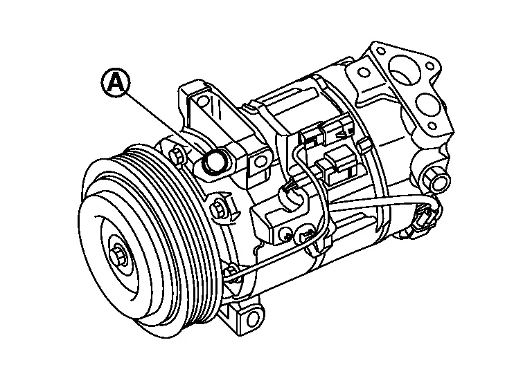
Drain lubricant from removed A/C compressor and measure lubricant amount.
-
Remove drain bolt
 , and then drain lubricant from drain port.
 -
Measure total amount of lubricant that is drained from removed A/C compressor.
Drain lubricant from a new A/C compressor that is calculated according to the following conditions.
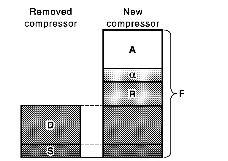
| Amount to be drained (A) [m (Imp fl oz)] = F ŌłÆ (D + S + R + ╬▒) |
|
| F | : Lubricant amount that a new A/C compressor contains [110 (3.9)] |
| D | : Lubricant amount that is drained from removed A/C compressor |
| S | : Lubricant amount that remains inside of removed A/C compressor [20 (0.7)] |
| R | : Lubricant amount to be added according to components that are removed except A/C compressor |
| ╬▒ | : Lubricant amount that is recycled together with refrigerant during recycle operation |
CAUTION:
If lubricant amount that is drained from removed A/C compressor is less than 60 m (2.1 Imp fl oz), perform calculation by setting ŌĆ£DŌĆØ as 40 m (1.4 Imp fl oz).
| Conditions |
Lubricant amount to be added to A/C system m (Imp fl oz) |
|---|---|
| Replace evaporator | 35 (1.2) |
| Replace condenser & liquid tank | 20 (0.7) |
Example: Lubricant amount to be drained from a new A/C compressor
when replacing A/C compressor and condenser & liquid tank [m (Imp fl oz)] [D = 60 (2.1), ╬▒ = 5 (0.2)]
110 (3.9) ŌłÆ [60 (1.6) + 20 (0.7) + 5 (0.2)] = 15 (ŌłÆ0.9)
Tighten drain bolt to the specified torque
| Specified torque | : 30 N┬Ęm (3.1 kg-m, 22 ft-lb) |
Install A/C compressor and check the operation.
Performance Test
Inspection
INSPECTION PROCEDURE
-
Connect recovery/recycling/recharging equipment (for HFO-1234yf) or manifold gauge.
-
Start the engine, and set to the following condition.
Test condition Surrounding condition Indoors or in the shade (in a well-ventilated place) Nissan Ariya Vehicle condition Door Closed Door glass Full open Hood Open Engine speed Idle speed A/C condition Temperature control switch or dial Full cold A/C switch ON Air outlet VENT (ventilation) Intake door position Recirculation Fan (blower) speed Maximum speed set -
Maintain test condition until A/C system becomes stable. (Approximately 10 minutes)
-
Check that test results of ŌĆ£recirculating-to-discharge air temperatureŌĆØ and ŌĆ£ambient air temperature-to-operating pressureŌĆØ are within the specified value.
-
When test results are within the specified value, inspection is complete.
If any of test result is out of the specified value, perform diagnosis by gauge pressure. Refer to Symptom Table.
RECIRCULATING-TO-DISCHARGE AIR TEMPERATURE TABLE
| Inside air (Recirculating air) at blower assembly inlet |
Discharge air temperature from center ventilator ┬░C (┬░F) | |
|---|---|---|
|
Relative humidity % |
Air temperature ┬░C (┬░F) | |
| 50 ŌĆō 60 | 20 (68) | 4.9 ŌĆō 6.9 (41 ŌĆō 44) |
| 25 (77) | 8.9 - 11.4 (48.0 - 52.5) | |
| 30 (86) | 12.6 - 15.6 (54.7 - 60.1) | |
| 35 (95) | 17.2 - 20.7 (63.0 - 69.3) | |
| 60 ŌĆō 70 | 20 (68) | 6.9 ŌĆō 8.9 (44 ŌĆō 48) |
| 25 (77) | 11.4 - 13.9 (52.5 - 57.0) | |
| 30 (86) | 15.6 - 18.6 (60.1 - 65.5) | |
| 35 (95) | 20.7 - 24.2 (69.3 - 75.6) | |
AMBIENT AIR TEMPERATURE-TO-OPERATING PRESSURE TABLE
| Fresh air |
High-pressure (Discharge side) kPa (kg/cm2, psi) |
Low-pressure (Suction side) kPa (kg/cm2, psi) | |
|---|---|---|---|
|
Relative humidity % |
Air temperature ┬░C (┬░F) | ||
| 50 ŌĆō 60 | 25 (77) |
1,154 ŌĆō 1,282 (11.8 ŌĆō 13.1, 167,3 ŌĆō 185.9) |
246 ŌĆō 273 (2.5 ŌĆō 2.8, 35.6 ŌĆō 39.6) |
| 30 (86) |
1,243 ŌĆō 1,381 (12.7 ŌĆō 14.1, 180.2 ŌĆō 200.2) |
278 ŌĆō 309 (2.8 ŌĆō 3.2, 40.4 ŌĆō 44.9) |
|
| 35 (95) |
1,195 ŌĆō 1,327 (12.2 ŌĆō 13.5, 173.2 ŌĆō 192.5) |
298 ŌĆō 331 (3.0 ŌĆō 3.4, 43.3 ŌĆō 48.1) |
|
| 40 (104) |
1,407 ŌĆō 1,563 (14.4 ŌĆō 15.9, 204.0 ŌĆō 226.7) |
364 ŌĆō 404 (3.7 ŌĆō 4.1, 52.7 ŌĆō 58.6) |
|
| 60 ŌĆō 70 | 25 (77) |
1,282 ŌĆō 1,410 (13.1 ŌĆō 14.4, 185.9 ŌĆō 204.4) |
273 ŌĆō 300 (2.8 ŌĆō 3.1, 39.6 ŌĆō 43.5) |
| 30 (86) |
1,381 ŌĆō 1,519 (14.1 ŌĆō 15.5, 200.2 ŌĆō 220.3) |
309 ŌĆō 340 (3.2 ŌĆō 3.5, 44.9 ŌĆō 49.4) |
|
| 35 (95) |
1,327 ŌĆō 1,460 (13.5 ŌĆō 14.9, 192.5 ŌĆō 211.7) |
331 ŌĆō 365 (3.4 ŌĆō 3.7, 48.1 ŌĆō 52.9) |
|
| 40 (104) |
1,563 ŌĆō 1,720 (15.9 ŌĆō 17.5, 226.7 ŌĆō 249.3) |
404 ŌĆō 444 (4.1 ŌĆō 4.5, 58.6 ŌĆō 64.4) |
|
Other materials:
P0011 Ivt Control
DTC Description
DTC DETECTION LOGIC DTC
CONSULT screen terms
(Trouble diagnosis content)
DTC detection condition
P0011
00
INT/V TIM CONT-B1
(ŌĆ£AŌĆØ Camshaft position - timing over-advanced or system performance bank 1)
Diagnosis condition
Engine running
Signal (term ...
P0500 Vss
DTC Description
DESCRIPTIONECM receives vehicle speed signals from two
different paths via CAN communication line: One is from the ABS actuator
and electric unit (control unit) via the combination unit and the other
is from TCM.DTC DETECTION LOGIC DTC
CONSULT screen terms
(Trouble diagno ...
Dtc/circuit Diagnosis. Drive Mode Select Switch Circuit
Diagnosis Procedure
CHECK DRIVE MODE SELECT SWITCH SIGNAL CIRCUIT
Ignition switch OFF.
Disconnect drive mode select switch harness connector and BCM harness connector.
Check the continuity between drive mode select switch harness connector and BCM harness connector.
2WD models with ...