Nissan Rogue (T33) 2021-Present Service Manual: Kr15ddt :: System Description
Component Parts
Refrigeration System
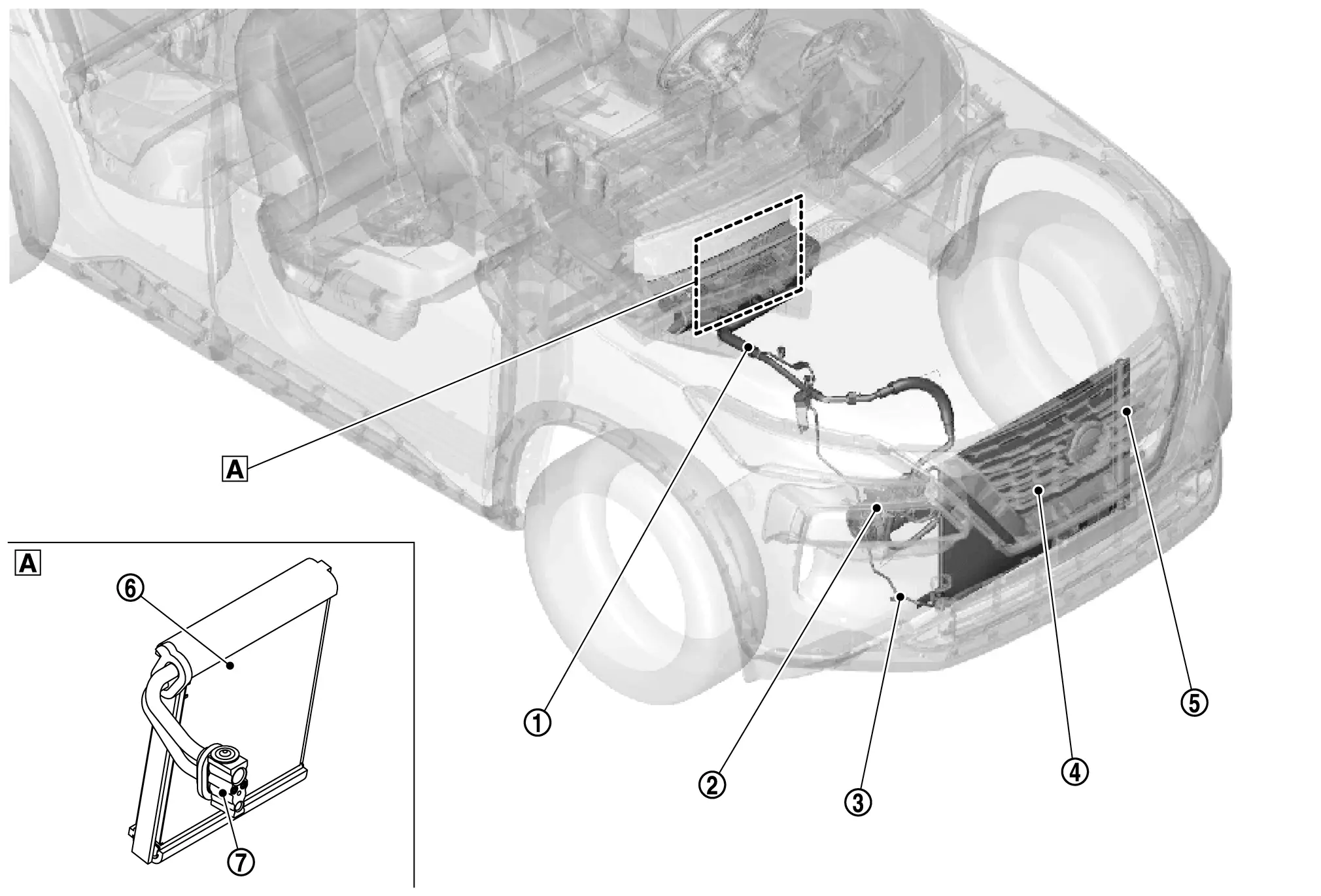
Component Parts Location
 |
In the heater & cooling unit assembly |
| No. | Location | Function |
|---|---|---|
 |
Internal heat exchanger pipe | Refer to Internal Heat Exchanger Pipe. |
 |
A/C Compressor | Refer to A/C Compressor. |
 |
Refrigerant pressure sensor |
|
 |
Condenser | Refer to Condenser. |
 |
Liquid Tank | Refer to Liquid Tank. |
 |
Evaporator | Refer to Evaporator. |
 |
Expansion Valve | Refer to Expansion Valve. |
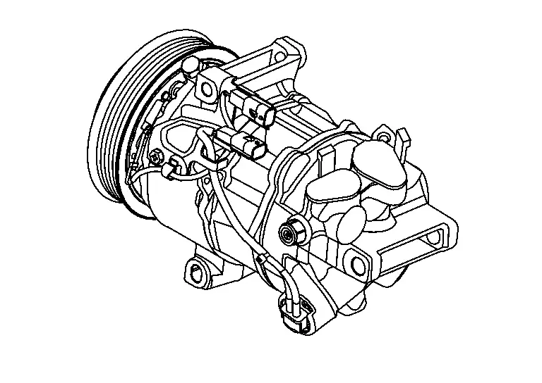
A/C Compressor
Intakes, compresses, and discharges refrigerant, to circulate refrigerant inside the refrigerant cycle.
Condenser
DESCRIPTION
-
A sub-cool condenser that combines a parallel-flow condenser and liquid tank in the sub-cool cycle is used.
-
Cools refrigerant discharged from compressor, and transforms it to liquid refrigerant.
STRUCTURE AND OPERATION
The sub-cool section is installed on the condenser, and the liquid refrigerant that exits the liquid tank is further cooled by the condenser sub-cool section, increasing the amount of heat that the liquid refrigerant can absorb and improving cooling performance.
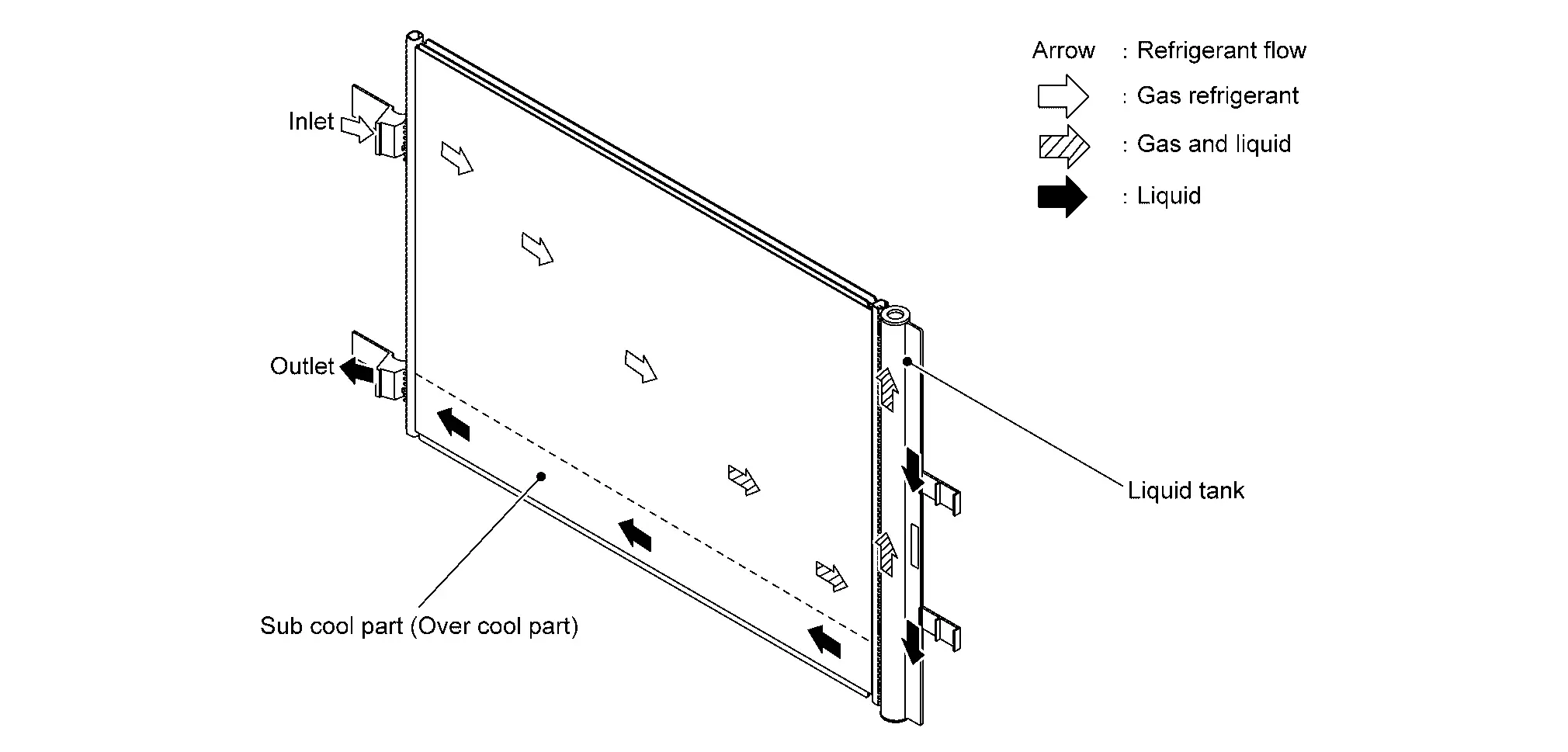
Liquid Tank
-
A liquid tank compatible with HFO-1234yf refrigerant is used.
-
Eliminates foreign matter in refrigerant, and stores temporarily liquid refrigerant.
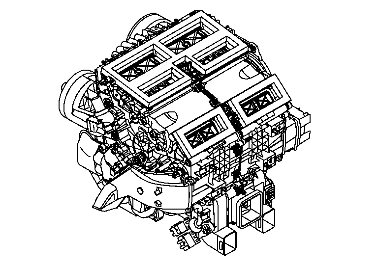
Heater & Cooling Unit Assembly
This system utilizes a heater & cooling unit that combines heater unit, and cooling unit.
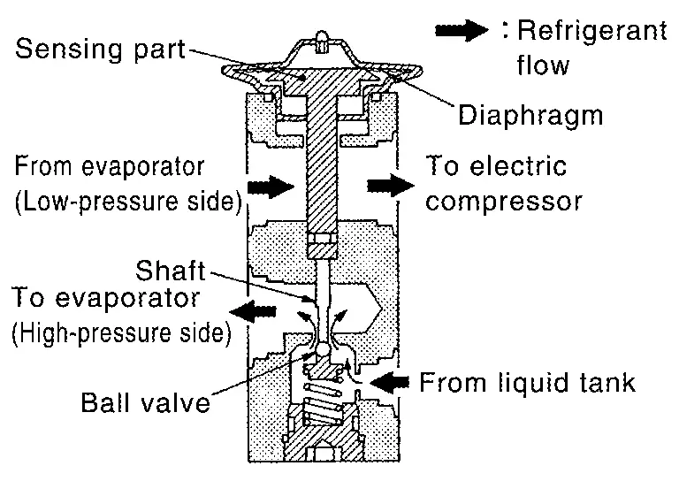
Expansion Valve
The refrigerant temperature is detected by the temperature sensing part located in low-pressure refrigerant path inside expansion valve. The lift amount of high-pressure side ball valve is changed to regulate the refrigerant flow.
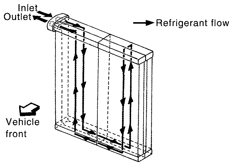
Evaporator
-
A thin laminate pipeless evaporator is used.
-
The mist from liquid refrigerant transforms to gas by evaporation by the air conveyed from blower motor. The air is cooled by the heat by evaporation.
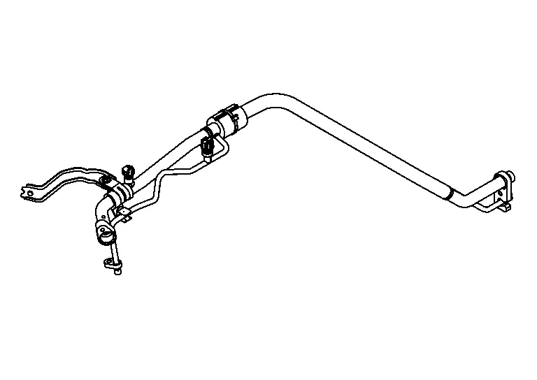
Internal Heat Exchanger Pipe
Transfers heat out of the liquid refrigerant, sub cooling it below condensation temperature.
System
System Diagram
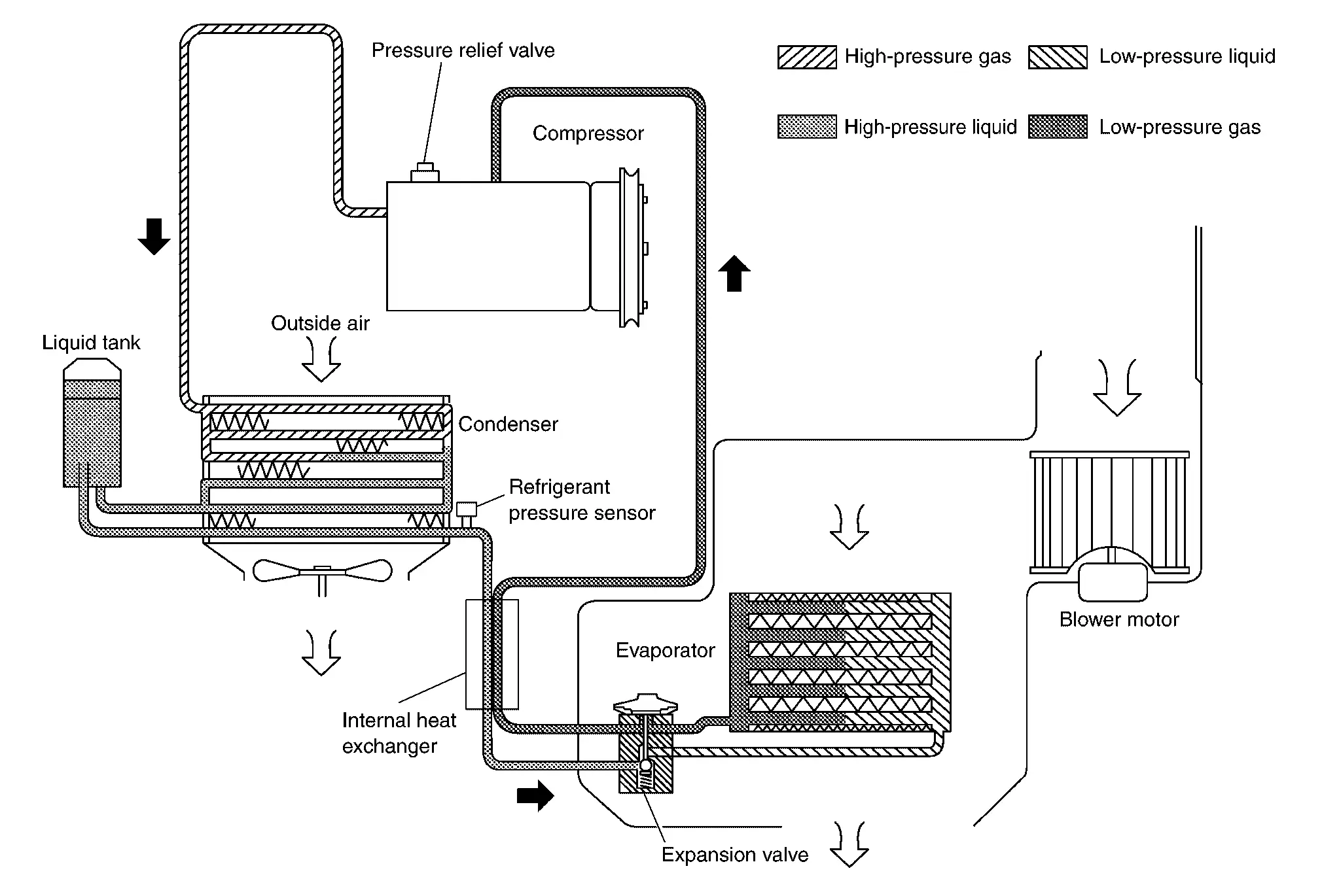
System Description
REFRIGERANT CYCLE
Refrigerant Flow
The refrigerant from the A/C compressor, flows the condenser with liquid tank, the evaporator, and returns to the A/C compressor. The refrigerant evaporation in the evaporator is controlled by an expansion valve.
Freeze Protection
-
AUTOMATIC AIR CONDITIONING SYSTEM: Refer to A/C Compressor Control.
-
MANUAL AIR CONDITIONING SYSTEM: Refer to A/C Compressor Control.
REFRIGERANT SYSTEM PROTECTION
Refrigerant Pressure Sensor
-
The refrigerant system is protected against excessively high- or low-pressures by the refrigerant pressure sensor, located on the high-pressure pipe. The refrigerant pressure sensor detects the pressure inside the refrigerant line and sends the voltage signal to the ECM if the system pressure rises above, or falls below the specifications.
-
ECM turns the A/C relay to OFF and stops the A/C compressor when the high-pressure side detected by refrigerant pressure sensor.
Pressure Relief Valve
The refrigerant system is also protected by a pressure relief valve, located in the rear head of the A/C compressor. The release port on the pressure relief valve automatically opens and releases refrigerant into the atmosphere when the pressure of refrigerant in the system increases to an unusual level [more than 3,800 kPa (38.0 bar, 38.8 kg/cm2, 551 psi)].
Other materials:
Removal and Installation. Intelligent Key Unit
Removal and Installation
REMOVALCAUTION:
When replacing the Intelligent Key unit, always replace it
with a new one. The functions controlled by the Intelligent Key unit
does not operate properly in case of reuse of the Intelligent Key unit
from another Nissan Ariya vehicle.
Remove the instr ...
Transfer: Ty92a. Periodic Maintenance. Transfer Oil
Transfer Oil
Inspection
OIL LEAKAGE
Remove engine under cover during working. Refer to Exploded View.
Check transfer surrounding area (oil seal, drain plug, and filler plug etc.) for oil leakage.OIL LEVEL
Remove engine under cover during working. Refer to Exploded View.
Check oil level ...
P2615 Intake Camshaft Position Sensor
DTC Description
DTC DETECTION LOGIC DTC
CONSULT screen terms
(Trouble diagnosis content)
DTC detection condition
P2615
00
A camshaft posi signal B1
(Camshaft A Position Signal Output Circuit Low Bank 1)
Diagnosis condition
Engine running at idle
Signal (terminal)
...