Nissan Rogue (T33) 2021-Present Service Manual: Cylinder Block
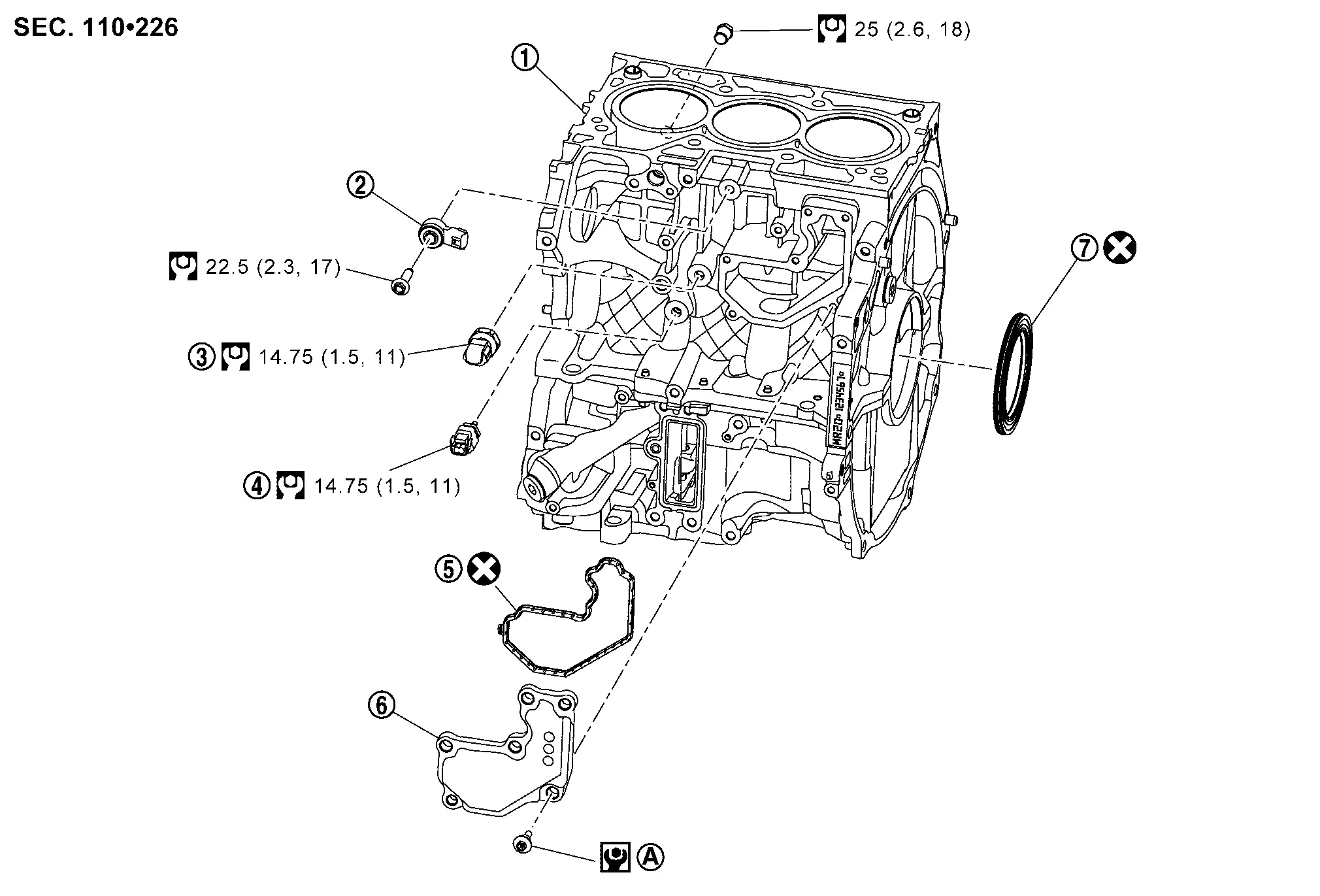
Exploded View
CAUTION:
Never disassemble or remove components beyond the configuration shown in the figure.
 |
Cylinder block |  |
Knock sensor |  |
Engine oil pressure sensor |
 |
Engine oil temperature sensor |  |
Breather separator assembly gasket |  |
Breather separator assembly |
 |
Rear oil seal | ||||
 |
Comply with the installation procedure when tightening. Refer to Disassembly & Assembly. | ||||
 |
: N·m (kg-m, ft-lb) | ||||
 |
: N·m (kg-m, in-lb) | ||||
 |
: Always replace after every disassembly. | ||||
Disassembly & Assembly
 NOTE:
NOTE:
Sensors are removable with the engine mounted in the Nissan Ariya vehicle.
CYLINDER BLOCK
DISASSEMBLY
Remove each plug to cylinder block, if necessary.
ASSEMBLY
CAUTION:
Do not reuse O-rings or gaskets.
Install each plug to cylinder block, if removed.
-
Apply liquid gasket to the thread of water drain plug .
Use Genuine RTV Silicone Sealant or an equivalent. Refer to Recommended Chemical Products and Sealants.
CAUTION:
If cylinder block assembly removed or replaced, perform "ELECTRIC IVT CONTROL ACTUATOR POSITION LEARNING". Refer to Description.
KNOCK SENSOR
REMOVAL
Remove the intake manifold. Refer to Removal and Installation.
Disconnect the harness connector from the knock sensor.
Remove knock sensor.
CAUTION:
Handle it carefully and avoid impacts.
INSTALLATION
Install knock sensor in the direction shown in the figure.
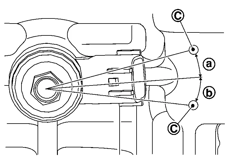
| a. | : 10.7° |
| b. | : 10.4° |
| C. | : Convex point (acceptable area of connector direction) |
CAUTION:
-
Never tighten mounting bolts while holding the harness connector.
-
If any impact by dropping is applied to knock sensor, replace it with a new one.
NOTE:
-
Check that there is no foreign material on the cylinder block mating surface and the back surface of knock sensor.
-
Check that knock sensor does not interfere with other parts.
Installation of the remaining components is in the reverse order of removal.
ENGINE OIL PRESSURE SENSOR
REMOVAL
Remove the sub starter & generator. Refer toRemoval and Installation .
Remove the sub starter & generator and compressor bracket. Refer to Exploded View.
Disconnect the harness connector from the engine oil pressure sensor.
Remove the engine oil pressure sensor.
INSTALLATION
Apply liquid gasket to the threads of the engine oil pressure sensor.
Use Genuine RTV Silicone Sealant or an equivalent. Refer to Recommended Chemical Products and Sealants.
CAUTION:
Do not reuse engine oil pressure sensor if it has been dropped.
Install engine oil pressure sensor and tighten to the specified torque.
Installation of the remaining components is in the reverse order of removal.
ENGINE OIL TEMPERATURE SENSOR
REMOVAL
Remove the sub starter & generator. Refer to Removal and Installation.
Remove the sub starter & generator and compressor bracket. Refer to Exploded View.
Disconnect the harness connector from the engine oil temperature sensor.
Remove the engine oil temperature sensor.
INSTALLATION
Apply liquid gasket to the threads of the engine oil temperature sensor.
Use Genuine RTV Silicone Sealant or an equivalent. Refer to Recommended Chemical Products and Sealants.
CAUTION:
Do not reuse engine oil temperature sensor if it has been dropped.
Install engine oil temperature sensor and tighten to the specified torque.
Installation of the remaining components is in the reverse order of removal.
BREATHER SEPARATOR ASSEMBLY
REMOVAL
Remove the intake manifold support. Refer to Removal and Installation.
Remove the bracket (2). Refer to Exploded View.
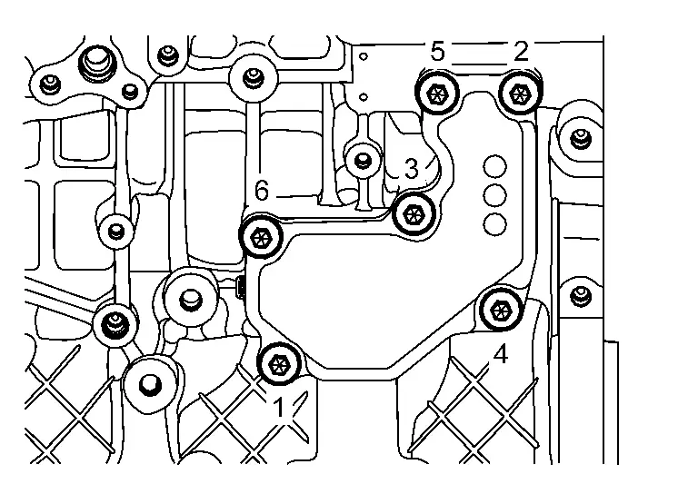
Loosen mounting bolts in reverse order as shown in the figure, and then remove breather separator assembly.
INSTALLATION
Install the breather separator assembly and tighten bolts in numerical order as shown in the figure.
| Breather separator assembly | ||
| First tighten |
: 1.96 N·m (0.2 kg-m, 17 in-lb) | |
| Second tighten |
: 8.33 N·m (0.85 kg-m, 74 in-lb) | |
Inspection
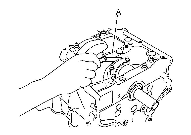
CRANKSHAFT END PLAY
-
Measure the clearance between thrust bearings and crankshaft arm when crankshaft is moved fully forward or backward with a dial indicator (A).
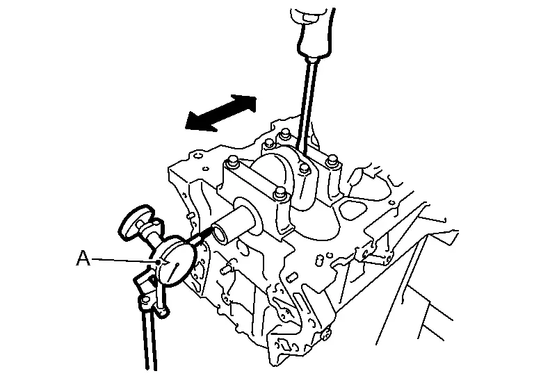
Standard and Limit : Refer to Cylinder Block. -
If the measured value exceeds the limit, replace thrust bearings, and measure again. If it still exceeds the limit, replace crankshaft also.
CONNECTING ROD SIDE CLEARANCE
-
Measure the side clearance between connecting rod and crankshaft arm with a feeler gauge (A).
Standard and Limit : Refer to Cylinder Block. -
If the measured value exceeds the limit, replace connecting rod, and measure again. If it still exceeds the limit, replace crankshaft also.
CYLINDER BLOCK TOP SURFACE DISTORTION
-
Using a scraper, remove gasket on the cylinder block surface, and also remove engine oil, scale, carbon, or other contamination.
CAUTION:
Be careful not to allow gasket flakes to enter engine oil or engine coolant passages.
-
Measure the distortion on the cylinder block upper face at some different points in six directions with a straight edge (A) and feeler gauge (B).
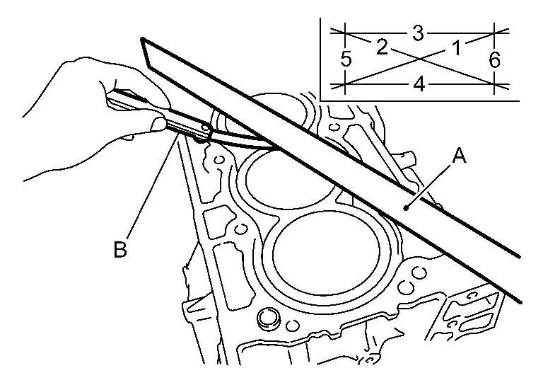
Limit : Refer to Cylinder Block. -
If it exceeds the limit, replace cylinder block.
Cylinder Bore Inner Diameter
-
Using a cylinder gauge, measure the cylinder bore for wear, out-of-round and taper at six different points on each cylinder. [
and  directions at
  , and
, and  ] [ is in longitudinal direction of engine]
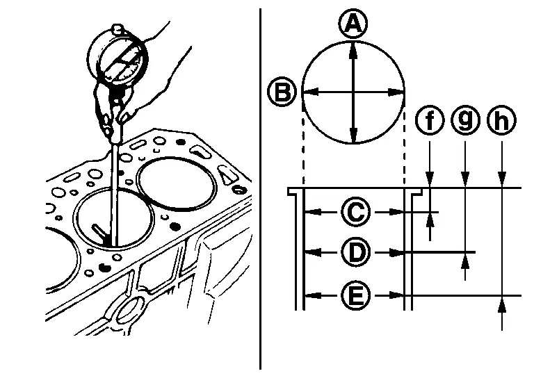

: Not applicable 
: 15 mm (0.59 in) 
: 60 mm (2.36 in) 
: — NOTE:
When determining cylinder bore grade, measure the cylinder bore
direction at position.Standard: Cylinder bore inner diameter : Refer to Cylinder Block. Limit: Out-of-round [Difference between and ] Taper [Difference between and ] : Refer to Cylinder Block. -
If the measured value exceeds the limit, or if there are scratches and/or seizure on the cylinder inner wall, replace cylinder block.
NOTE:
Oversize piston is not provided.
Other materials:
Can Fundamental. Trouble Diagnosis
Component Description
System Description
Component Description
Main line
CAN communication line between splices
Branch line
CAN communication line between splice and a control unit
Splice
A point connecting a branch line with a main line
Termination circuit
Circuit ...
Telematics System. System Description
Component Parts
With 8" Color Display
Component Parts Location
No. Component Function
1.
Telematics switch
Refer to Telematics Switch.
2.
Microphone
Refer to Microphone.
3.
Air bag diagnosis sensor unit
Provides TCU with the car crash information signal via C ...
Electric Intake Valve Timing Control Module
Values On The Diagnosis Tool
VALUES ON THE DIAGNOSIS TOOLNOTE:
The following table includes information (items) inapplicable to this
Nissan Ariya vehicle. For information (items) applicable to this
vehicle, refer to CONSULT display items.
Numerical values in the following table are re ...