Nissan Rogue (T33) 2021-Present Service Manual: Kr15ddt :: Service Data and Specifications (sds). Service Data and Specifications (sds)
Service Data and Specifications (sds)
General Specification
GENERAL SPECIFICATIONS
| Engine type | KR15DDT | ||||
| Cylinder arrangement | In-line 3 | ||||
| Displacement cm3 (cu in) | Low compression | 1,497 (91.40) | |||
| High compression | 1,477 (90.10) | ||||
| Bore and stroke mm (in) | Low compression | 84.0Ă—90.1 (3.307Ă—3.547) | |||
| High compression | 84.0Ă—88.9 (3.307Ă—3.500) | ||||
| Valve arrangement | DOHC | ||||
| Firing order | 1-2-3 | ||||
| Number of piston rings | Compression | 2 | |||
| Oil | 1 | ||||
| Compression ratio | Low compression | 8.0:1 | |||
| High compression | 14.0:1 | ||||
|
Compression pressure kPa (bar, kg/cm2, psi)/250 rpm |
Standard | 1,530 (15.3, 15.6, 222) | |||
| Minimum | 1,280 (12.8, 13.1, 186) | ||||
| Differential limit between cylinders | 100 (1.0, 1.0, 15) | ||||
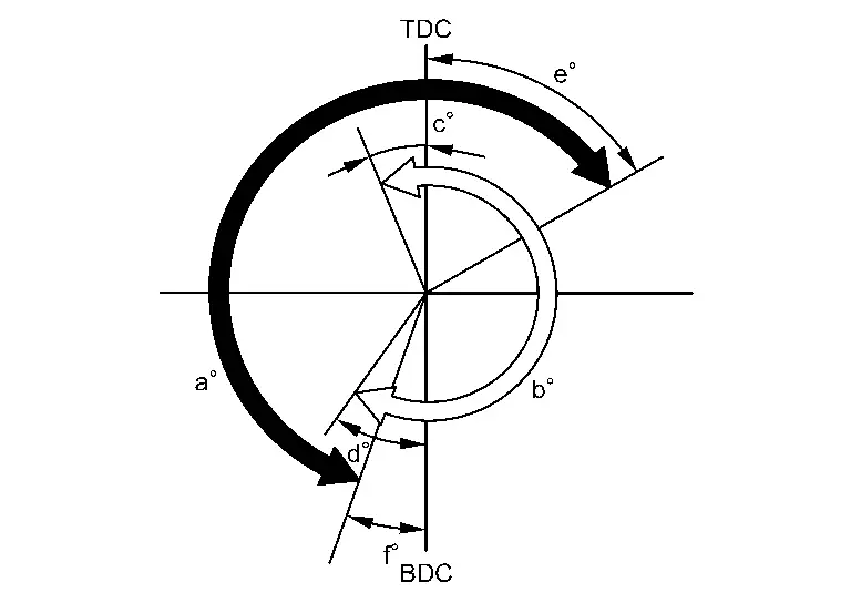
Unit: degree
|
Valve timing
 : Exhaust valve : Exhaust valve |
VTC Minimum phasing (Mechanical)
|
VTC Maximum phasing (Mechanical)
|
||||
|
a EXH valve opening angle |
b INT valve opening angle |
c INT open |
d INT close |
e EXH close |
f EXH open |
|
| VTC Minimum phasing (Mechanical) *1 | 224 | 240 |
44 ATDC |
104 ABDC |
2 ATDC |
42 BBDC |
| VTC Maximum phasing (Mechanical) *2 |
16 BTDC |
44 ABDC |
40 ATDC |
4 BBDC |
||
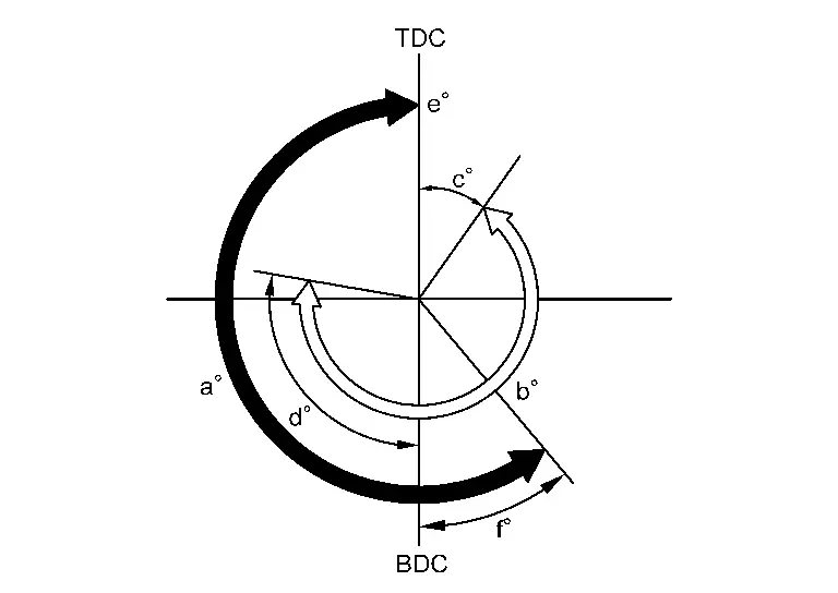
*1: When the intake or exhaust valve opening angle is at the minimum.
*2: When the intake or exhaust valve opening angle is at the maximum.
Drive Belt
DRIVE BELT
| Tension of drive belt | Belt tension is not necessary, as it is automatically adjusted by drive belt auto-tensioner. |
Spark Plug
SPARK PLUG
Unit: mm (in)
| Make | NGK | |
| Standard type | ILMAR8G8GS | |
| Gap (Nominal) | Standard | 0.8 – 0.9 (0.031 – 0.035) |
Intake Manifold
Unit: mm (in)
| Items | Limit |
|---|---|
| Surface distortion | 1.0(0.039) |
Turbocharger
EXHAUST MANIFOLD
Unit: mm (in)
| Items | Limit |
|---|---|
| Surface distortion | 0.3 (0.012) |
Camshaft
CAMSHAFT
Unit: mm (in)
| Items | Standard | Limit | |||
| Camshaft journal oil clearance | No. 1 | — | — | ||
| No. 2, 3, 4, 5 | 0.030 - 0.071 (0.0012 - 0.0028) | 0.15 (0.0059) | |||
| Camshaft bracket inner diameter | No. 1 | 52.000 - 52.021 (2.0472 - 2.0481) | — | ||
| No. 2, 3, 4, 5 | 25.000 - 25.021 (0.9843 - 0.9851) | — | |||
| Camshaft journal diameter | No. 1 | 27.941 - 27.956 (1.1000 - 1.1006) | — | ||
| No. 2, 3, 4, 5 | 24.950 - 24.970 (0.9823 - 0.9831) | — | |||
| Camshaft end play | 0.075 - 0.153 (0.0030 - 0.0060) | 0.24 (0.0094) | |||
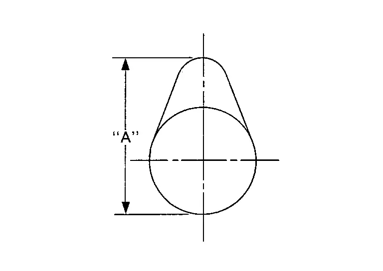
| Camshaft cam height “A” | Intake | 45.265 - 45.455 (1.7821 - 1.7896) | 45.16 (1.7779) | ||
| Exhaust | 43.275 - 43.465 (1.7037 - 1.7112) | 43.17 (1.6996) | |||
| Camshaft runout [TIR*] | Less than 0.01 (0.0004) | 0.05 (0.0020) | |||
| Camshaft sprocket runout [TIR*] | — | 0.15 (0.0059) | |||
| Bearing position | 3.3 – 4.0 (0.130 – 0.157) | — | |||
|
|
|||||
*: Total indicator reading
VALVE LIFTER
Unit: mm (in)
| Items | Standard | |
| Valve lifter outer diameter | Intake | 33.980 - 33.990 (1.3378 - 1.3382) |
| Exhaust | 29.977 - 29.987 (1.1802 - 1.1806) | |
| Valve lifter hole diameter | Intake | 34.000 - 34.021 (1.3386 - 1.3394) |
| Exhaust | 30.000 - 30.021 (1.1811 - 1.1819) | |
| Valve lifter clearance | 0.013 - 0.044 (0.0005 - 0.0017) |
VALVE CLEARANCE
Unit: mm (in)
| Items | Cold | Hot* (reference data) |
|---|---|---|
| Intake | 0.28 - 0.36 (0.011 - 0.014) | 0.304 - 0.416 (0.012 - 0.016) |
| Exhaust | 0.27 - 0.35 (0.011 - 0.014) | 0.308 - 0.432 (0.012 - 0.017) |
*: Approximately 80°C (176°F)
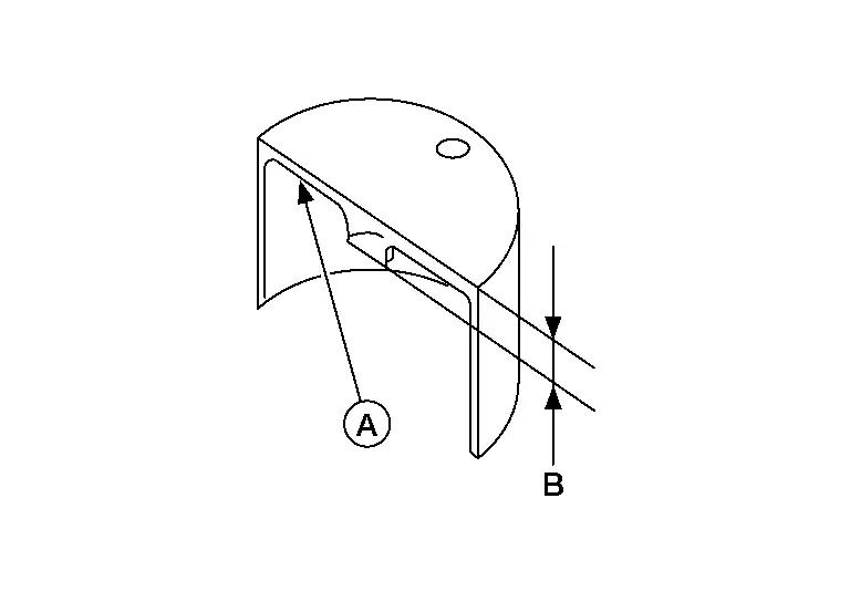
AVAILABLE VALVE LIFTER
Unit: mm (in)
Identification mark  | Thickness (B) | |
|---|---|---|
| Intake | Exhaust | |
| 300r | 300h | 3.00 (0.1181) |
| 302r | 302h | 3.02 (0.1189) |
| 304r | 304h | 3.04 (0.1197) |
| 306r | 306h | 3.06 (0.1205) |
| 308r | 308h | 3.08 (0.1213) |
| 310r | 310h | 3.10 (0.1220) |
| 312r | 312h | 3.12 (0.1228) |
| 314r | 314h | 3.14 (0.1236) |
| 316r | 316h | 3.16 (0.1244) |
| 318r | 318h | 3.18 (0.1252) |
| 320r | 320h | 3.20 (0.1260) |
| 322r | 322h | 3.22 (0.1268) |
| 324r | 324h | 3.24 (0.1276) |
| 326r | 326h | 3.26 (0.1283) |
| 328r | 328h | 3.28 (0.1291) |
| 330r | 330h | 3.30 (0.1299) |
| 332r | 332h | 3.32 (0.1307) |
| 334r | 334h | 3.34 (0.1315) |
| 336r | 336h | 3.36 (0.1323) |
| 338r | 338h | 3.38 (0.1331) |
| 340r | 340h | 3.40 (0.1339) |
| 342r | 342h | 3.42 (0.1346) |
| 344r | 344h | 3.44 (0.1354) |
| 346r | 346h | 3.46 (0.1362) |
| 348r | 348h | 3.48 (0.1370) |
| 350r | 350h | 3.50 (0.1378) |
|
|
||
Cylinder Head
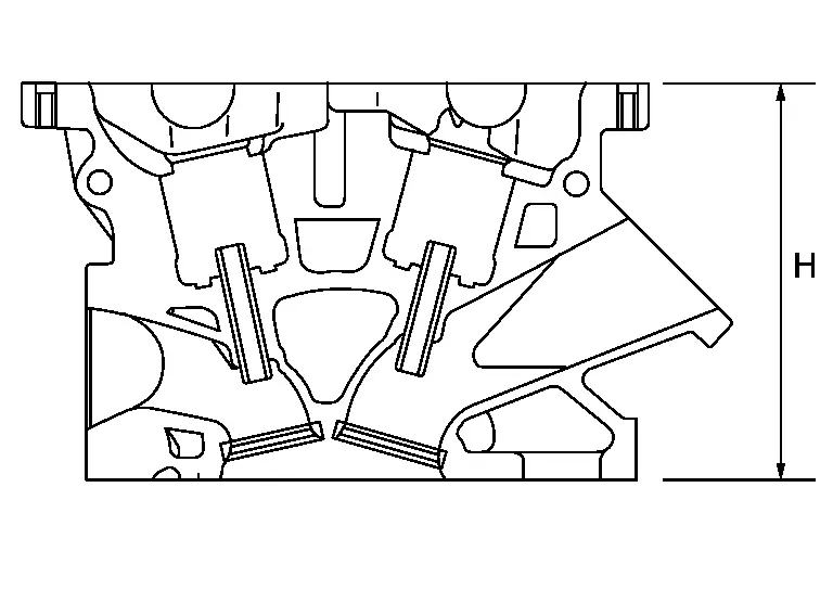
CYLINDER HEAD
Unit: mm (in)
| Items | Standard | Limit |
|---|---|---|
| Head surface distortion | — | 0.1 (0.004) |
| Normal cylinder head height “H” | 130.9 (5.15) | — |
|
|
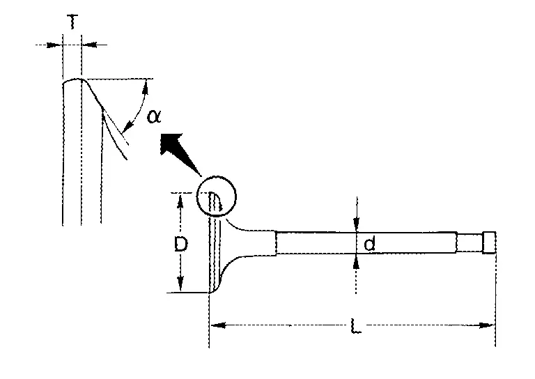
VALVE DIMENSIONS
Unit: mm (in)
|
|
||
| Valve head diameter “D” | Intake | 33.8 - 34.1 (1.331 - 1.343) |
| Exhaust | 27.6 - 27.9 (1.087 - 1.098) | |
| Valve length “L” | Intake | 106.42 (4.19) |
| Exhaust | 105.41 (4.15) | |
| Valve stem diameter “d” | Intake | 5.465 - 5.480 (0.2152 - 0.2157) |
| Exhaust | 5.455 - 5.470 (0.2148 - 0.2154) | |
| Valve seat angle “α” | 45°15′ - 45°45′ | |
| Valve margin “T” | Intake | 1.2 (0.047) |
| Exhaust | 1.45 (0.0571) | |
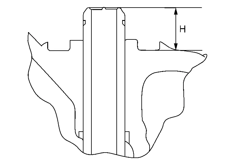
VALVE GUIDE
Unit: mm (in)
|
|
||||
| Items | Standard | Oversize (service) [0.2 (0.008)] | ||
| Valve guide | Outer diameter | 9.523 - 9.534 (0.3749 - 0.3754) | 9.723 - 9.734 (0.3828 - 0.3832) | |
| Inner diameter (Finished size) | 5.500 - 5.518 (0.2165 - 0.2172) | |||
| Cylinder head valve guide hole diameter | 9.475 - 9.496 (0.3730 - 0.3739) | 9.675 - 9.696 (0.3809 - 0.3817) | ||
| Interference fit of valve guide | 0.027 - 0.059 (0.0011 - 0.0023) | |||
| Items | Standard | Limit | ||
| Valve guide clearance | Intake | 0.020 - 0.053 (0.0008 - 0.0021) | 0.1 (0.004) | |
| Exhaust | 0.030 - 0.063 (0.0012 - 0.0025) | |||
| Projection length “H” | 13.35 - 13.65 (0.5256 - 0.5374) | |||
VALVE SEAT
Unit: mm (in)
|
|
|||
| Items | Standard | Oversize (service) [0.5 (0.02)] | |
| Cylinder head seat recess diameter “D” | Intake | 34.700 - 34.727 (1.3661 - 1.3672) | 35.200 - 35.227 (1.3858 - 1.3869) |
| Exhaust | 28.700 - 28.727 (1.1299 - 1.1310) | 29.200 - 29.227 (1.1496 - 1.1507) | |
| Valve seat outer diameter “d” | Intake | 34.797 - 34.813 (1.3700 - 1.3706) | 35.297 - 35.313 (1.3896 - 1.3903) |
| Exhaust | 28.808 - 28.824 (1.1342 - 1.1348) | 29.308 - 29.324 (1.1539 - 1.1545) | |
| Valve seat interference fit | Intake | 0.070 - 0.113 (0.0028 - 0.0044) | |
| Exhaust | 0.081 - 0.124 (0.0032 - 0.0049) | ||
| Diameter “d1”*1 | Intake | 31.8 (1.252) | |
| Exhaust | 25.3 (0.996) | ||
| Diameter “d2”*2 | Intake | 33.1 - 33.6 (1.303 - 1.323) | |
| Exhaust | 26.9 - 27.4 (1.059 - 1.079) | ||
| Angle “α1” | Intake | 70° | |
| Exhaust | 45° | ||
| Angle “α2” | 88°45′ - 90°15′ | ||
| Angle “α3” | 120° | ||
| Contacting width “W”*3 | Intake | 1.0 - 1.4 (0.039 - 0.055) | |
| Exhaust | 1.2 - 1.6 (0.047 - 0.063) | ||
| Height “h” | Intake | 5.13 – 5.23 (0.202 – 0.206) | 4.26 - 4.36 (0.168 - 0.172) |
| Exhaust | 5.9 - 6.0 (0.232 - 0.236) | 4.95 - 5.05 (0.1949 - 0.1988) | |
| Depth “H” | Intake | 5.27 (0.2075) | |
| Exhaust | 6.05 (0.2382) | ||
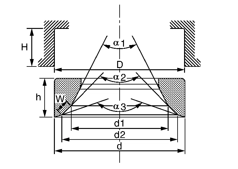
*1: Diameter made by intersection point of conic angles “α1” and “α2”
*2: Diameter made by intersection point of conic angles “α2” and “α3”
*3: Machining data
VALVE SPRING
| Items | Standard | |
|---|---|---|
| Intake | Exhaust | |
| Free height | 48.47 mm (1.9083 in) | 58.06 mm (2.2858 in) |
| Installation height | 38.24 mm (1.5055 in) | 38.46 mm (1.514 in) |
| Installation load | 158 - 178 N (16.2 - 18.1 kg, 35.6 - 40.0 lb) | 320 - 360 N (32.7 - 36.7 kg, 72.0 - 80.9 lb) |
| Height during valve open | 28.64 mm (1.1276 in) | 30.36 mm (1.195 in) |
| Load with valve open | 351 - 395 N (35.8 - 40.2 kg, 78.9 - 88.7 lb) | 461 - 519 N (47.1 - 52.9 kg, 103.7 - 116.6 lb) |
| Identification color | Yellow — Green | Blue |
Unit: mm (in)
| Items | Limit | |
|---|---|---|
| Valve spring squareness |
1.7 (0.067) 2.1 (0.083) |
|
Cylinder Block
CYLINDER BLOCK
Unit: mm (in)
| Cylinder block top surface distortion | Limit | 0.03 (0.0012) | ||
| Cylinder bore inner diameter | Standard | 84.000 - 84.015 (3.3071 - 3.3077) | ||
| Out-of-round | Limit | 0.015 (0.0006) | ||
| Taper | 0.010 (0.0004) | |||
CONNECTING ROD (C-link)
Unit: mm (in)
| Connecting rod (C-link) side clearance | Standard | 0.20 - 0.35 (0.0079 - 0.0138) | |
| Limit | 0.4 (0.016) | ||
CRANKSHAFT
Unit: mm (in)
| Crankshaft end play | Standard | 0.098 - 0.260 (0.0039 - 0.0102) | ||
| Limit | 0.3 (0.012) | |||
Other materials:
P0030 A/f Sensor 1 Heater
DTC Description
DTC DETECTION LOGIC DTC
CONSULT screen terms
(Trouble diagnosis content)
DTC detection condition
P0030
00
HO2S1 HTR (B1)
(HO2S heater control circuit bank 1 sensor 1)
Diagnosis condition
Engine running at idle
Signal (terminal)
A/F sensor 1 heater ...
Comment activer/désactiver la fonction de maintien de frein automatique
Comment activer la fonction de maintien de frein automatique
1. Lorsque le contact d’allumage du Nissan Rogue est placé sur la position ON, appuyez sur la commande de maintien de frein automatique 1. Le témoin lumineux de la commande de maintien de frein automatique 2 s’allume pour co ...
P0461 Fuel Level Sensor
DTC Description
DTC DETECTION LOGICDriving long distances naturally affect fuel gauge level.This diagnosis detects the fuel gauge malfunction of the gauge not moving even after a long distance has been driven. DTC
CONSULT screen terms
(Trouble diagnosis content)
DTC detection condition
...