Nissan Rogue (T33) 2021-Present Service Manual: Engine :: Engine Lubrication System
Kr15ddt :: Precaution. Precautions
Precautions
Precaution for Supplemental Restraint System (SRS) "AIR BAG" and SEAT BELT PRE-TENSIONER"
The Supplemental Restraint System such as “AIR BAG” and “SEAT BELT PRE-TENSIONER”, used along with a front seat belt, helps to reduce the risk or severity of injury to the driver and front passenger for certain types of collisions.
Information necessary to service the system safely is included in the “SRS AIR BAG” and “SEAT BELT” sections of this Service Manual.
WARNING:
Always observe the following items for preventing accidental activation:
-
To avoid rendering the SRS inoperative, which could increase the risk of personal injury or death in the event of a collision that would result in air bag inflation, it is recommended that all maintenance and repair be performed by an authorized NISSAN/INFINITI dealer.
-
Improper repair, including incorrect removal and installation of the SRS, can lead to personal injury caused by unintentional activation of the system. For removal of Spiral Cable and Air Bag Module, see “SRS AIR BAG”.
-
Never use electrical test equipment on any circuit related to the SRS unless instructed to in this Service Manual. SRS wiring harnesses can be identified by yellow and/or orange harnesses or harness connectors.
PRECAUTIONS WHEN USING POWER TOOLS (AIR OR ELECTRIC) AND HAMMERS
WARNING:
Always observe the following items for preventing accidental activation:
-
When working near the Air Bag Diagnosis Sensor Unit or other Air Bag System sensors with the ignition/power switch ON or engine running, never use air or electric power tools or strike near the sensor(s) with a hammer. Heavy vibration could activate the sensor(s) and deploy the air bag(s), possibly causing serious injury.
-
When using air or electric power tools or hammers, always switch the ignition/power switch OFF, disconnect the 12V battery or batteries, and wait at least 3 minutes before performing any service.
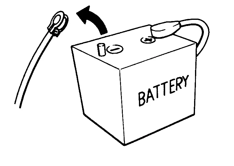
Precautions for Removing Battery Terminal
-
With the adoption of Auto ACC function, ACC power is automatically supplied by operating the Intelligent Key or remote keyless entry or by opening/closing the driver side door. In addition, ACC power is supplied even after the ignition switch is in the OFF position, i.e. ACC power is supplied for a certain fixed time.
-
When disconnecting the 12V battery terminal, place the ignition switch in the OFF position before disconnecting the 12V battery terminal, observing “How to disconnect 12V battery terminal” described below.
 NOTE:
NOTE:
Some ECUs operate for a certain fixed time even after ignition switch is in the OFF position and ignition power supply is stopped. If the battery terminal is disconnected before ECU stops, accidental DTC detection or ECU data damage may occur.
-
For Nissan Ariya vehicles with the 2-batteries, be sure to connect the main battery and the sub battery before placing the ignition switch in the ON position.
NOTE:
If the ignition switch is in the ON position with any one of the terminals of main battery and sub battery disconnected, then DTC may be detected.
-
After installing the 12V battery, always check "Self Diagnosis Result" of all ECUs and erase DTC.
NOTE:
The removal of 12V battery may cause a DTC detection error.
HOW TO DISCONNECT 12V BATTERY TERMINAL
Disconnect 12V battery terminal according to instruction described below.
-
Open the hood.
-
Place the ignition switch in the ON position.
-
Place the ignition switch in the OFF position with the driver side door opened.
-
Get out of the Nissan Ariya vehicle and close the driver side door.
-
Wait at least 3 minutes.
CAUTION:
While waiting, never operate the Nissan Ariya vehicle such as locking, opening, and closing doors. Violation of this caution results in the activation of ACC power supply according to the Auto ACC function.
-
Remove 12V battery terminal.
CAUTION:
After installing 12V battery, always check self-diagnosis results of all ECUs and erase DTC.
Precautions For Engine Service
DISCONNECTING FUEL PIPING
-
Before starting work, check no fire or spark producing items are in the work area.
-
Release fuel pressure before disconnecting and disassembly.
-
After disconnecting pipes, plug openings to stop fuel leakage.
DRAINING ENGINE COOLANT
Drain engine coolant and engine oil when the engine is cooled.
INSPECTION, REPAIR AND REPLACEMENT
-
Before repairing or replacing, thoroughly inspect parts. Inspect new replacement parts in the same way, and replace if necessary.
-
When replacing or inspecting air cleaner element, remove foreign matter inside air duct, on air cleaner element surface, and inside cleaner case.
REMOVAL AND DISASSEMBLY
-
When instructed to use SST, use specified tools. Always be careful to work safely, avoid forceful or uninstructed operations.
-
Exercise maximum care to avoid damage to mating or sliding surfaces.
-
Dowel pins are used for several parts alignment. When replacing and reassembling parts with dowel pins, check that dowel pins are installed in the original position.
-
Must cover openings of engine system with a tape or equivalent, to seal out foreign materials.
-
Mark and arrange disassembly parts in an organized way for easy troubleshooting and reassembly.
-
When loosening nuts and bolts, as a basic rule, start with the one furthest outside, then the one diagonally opposite, and so on. If the order of loosening is specified, do exactly as specified. Power tools may be used in the step.
ASSEMBLY AND INSTALLATION
-
Use torque wrench to tighten bolts or nuts to specification.
-
When tightening nuts and bolts, as a basic rule, equally tighten in several different steps starting with the ones in center, then ones on inside and outside diagonally in this order. If the order of tightening is specified, do exactly as specified.
-
Before removing or installing any intake-system-related parts, thoroughly clean them to prevent foreign matter from entering inside engine.
-
Replace with new gasket, packing, oil seal or O-ring.
-
Thoroughly wash, clean, and air-blow each part. Carefully check engine oil or engine coolant passages for any restriction and blockage.
-
Avoid damaging sliding or mating surfaces. Completely remove foreign materials such as cloth lint or dust. Before assembly, oil sliding surfaces well.
-
After disassembling, or exposing any internal engine parts, change engine oil and replace oil filter with a new one.
-
Release air within route when refilling after draining engine coolant.
-
After repairing, start the engine and increase engine speed to check engine coolant, fuel, engine oil, and exhaust gases for leakage.
Kr15ddt :: Preparation. Preparation
Preparation
Special Service Tools
|
Tool number Tool name | Description | |
|---|---|---|
|
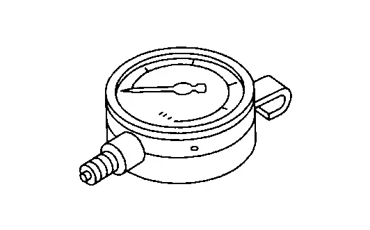
ST25051001 Oil pressure gauge |
|
Measuring oil pressure Maximum measuring range: 2,452 kPa (24.52 bar, 25 kg/cm2, 356 psi) |
|
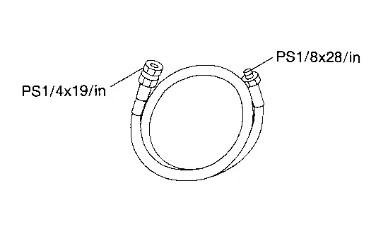
ST25052000 Hose |
|
Adapting oil pressure gauge to cylinder block |
|
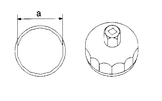
KV10115801 Oil filter wrench |
|
Removing and installing oil filter a: 64.3 mm (2.531 in) |
Commercial Service Tools
| Tool name | Description | |
|---|---|---|
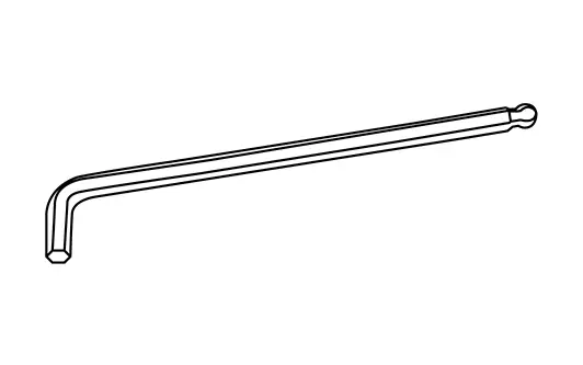
| Ball point hex wrench |
|
Removing and installing oil drain plug. |
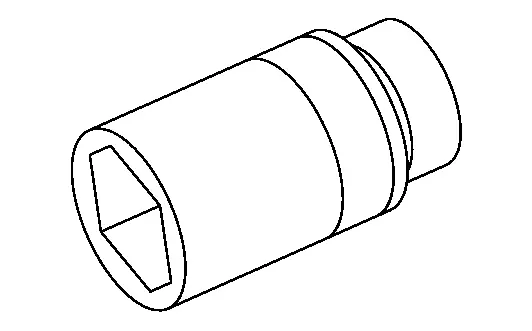
| Deep socket |
|
Removing and installing oil pressure sensor 27 mm (1.06 in) |
Always Replace with New Parts
| Never Reuse These Parts | Part Code | For additional information |
|---|---|---|
| Seal-O ring | 21014V | Exploded View |
| Ring-rubber | 21304 | Exploded View |
| Gasket-oil pump | 15025 | Exploded View |
| Washer-drain plug | 11128A | Exploded View |
| Plug-drain | 11128 | Exploded View |
Kr15ddt :: System Description. Description
Description
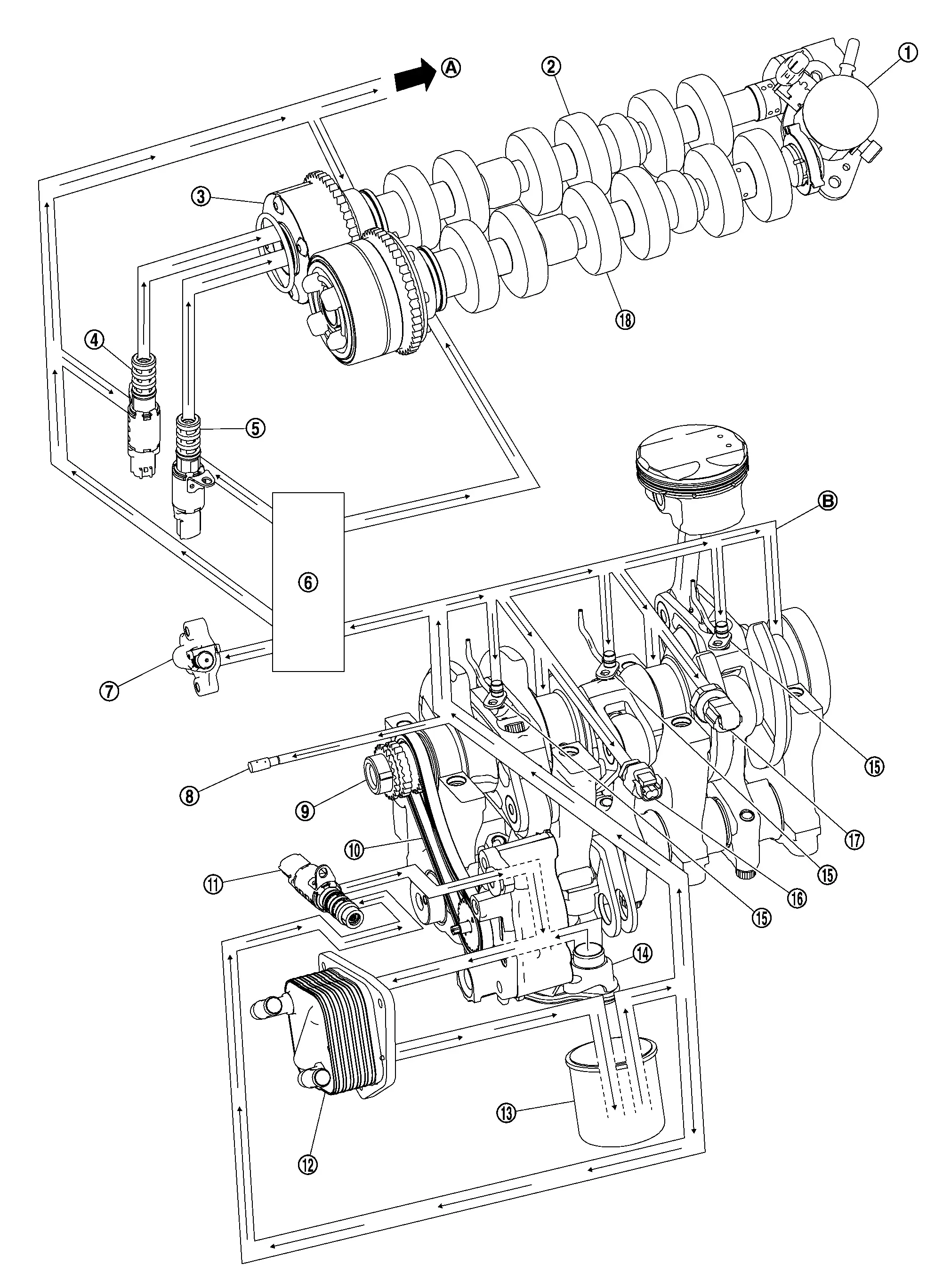
Engine Lubrication System
 |
High pressure fuel pump |  |
Camshaft (EXH) |  |
Camshaft sprocket (EXH) |
 |
Exhaust valve timing control solenoid valve |  |
Exhaust valve timing intermediate lock control solenoid valve |  |
Front cover |
 |
Timing chain tensioner |  |
Timing chain oil jet |  |
Crankshaft |
 |
Oil pump chain |  |
Engine oil pressure control solenoid valve |  |
Oil cooler |
 |
Oil filter |  |
Oil strainer |  |
Piston oil jet |
 |
Engine oil temperature sensor |  |
Engine oil pressure sensor |  |
Camshaft (INT) |
 |
To oil pan |  |
Main gallery |
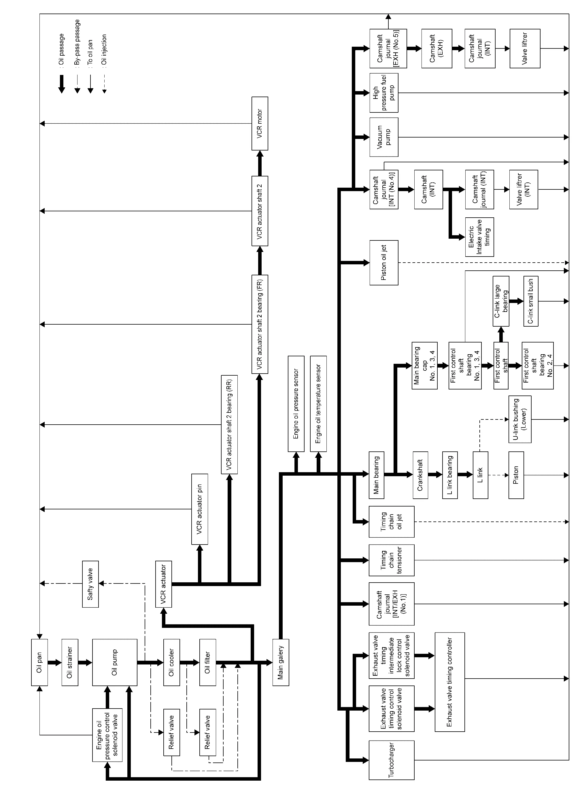
Engine Lubrication System Schematic
Kr15ddt :: Periodic Maintenance
Engine Oil
Inspection
ENGINE OIL LEVEL
NOTE:
Before starting engine, put vehicle horizontally and check the engine oil level. If engine is already started, stop it and allow 10 minutes before checking.
Pull out oil level gauge and wipe it clean.
Insert oil level gauge and check that the engine oil level is within the range shown in the figure.
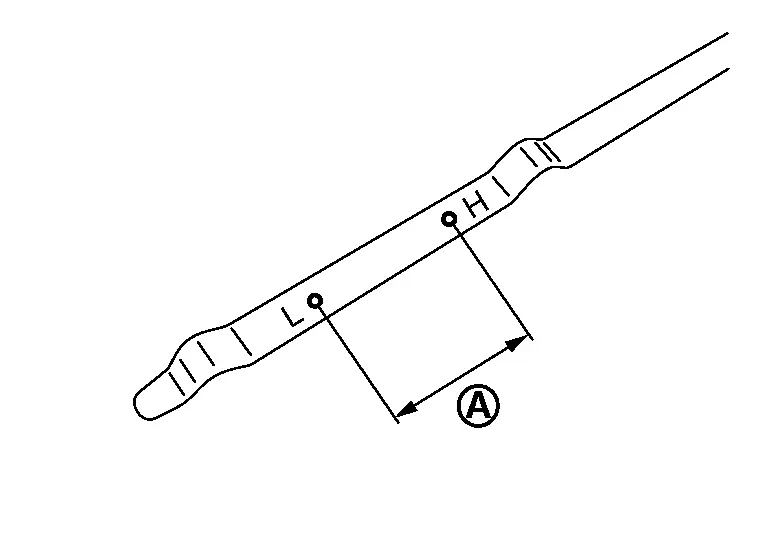
If it is out of range, adjust it and then recheck the oil level with the dipstick.
ENGINE OIL APPEARANCE
-
Check engine oil for white turbidity or heavy contamination.
-
If engine oil becomes turbid and white, it is highly probable that it is contaminated with engine coolant. Repair or replace damaged parts.
ENGINE OIL LEAKAGE
Check for engine oil leakage around the following area.
-
Oil pan (upper and lower)
-
Drain plug
-
Engine oil pressure sensor
-
Engine oil temperature sensor
-
Oil filter
-
Oil cooler
-
Exhaust valve timing intermediate lock control solenoid valve
-
Exhaust valve timing control solenoid valve
-
Front cover
-
Mating surface between cylinder block and cylinder head
-
Mating surface between cylinder head and camshaft bracket
-
Mating surface between cylinder head and rocker cover
-
Mating surface between camshaft bracket and rocker cover
-
Mating surface between camshaft position sensor bracket and high pressure fuel pump
-
Crankshaft oil seals (front and rear)
OIL PRESSURE CHECK
WARNING:
-
Be careful not to get burned, as engine oil may be hot.
-
When checking engine oil pressure, shift position should be “Parking position”, and apply parking brake securely.
Check engine oil level.
Disconnect harness connector at engine oil pressure sensor , and remove engine oil pressure sensor using a deep socket (commercial service tool).
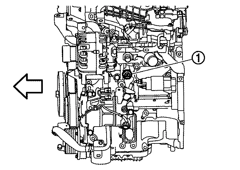
| : Engine front |
CAUTION:
Never drop or shock engine oil pressure sensor.
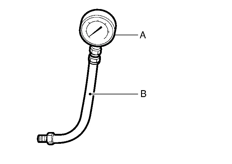
Install oil pressure gauge [SST: ST25051001] (A) and hose [SST: ST25052000] (B).
Start engine and warm it up to normal operating temperature.
Check oil pressure with engine running under no-load.
NOTE:
When engine oil temperature is low, engine oil pressure becomes high.
| Engine oil pressure | : Refer to Engine Oil Pressure. |
If difference is extreme, check oil passage and oil pump for oil leakage.
After the inspections, install engine oil pressure sensor as follows:Remove old liquid gasket adhering to engine oil pressure sensor and engine. Apply liquid gasket and tighten engine oil pressure sensor to specification.
Use Genuine RTV Silicone Sealant or an equivalent.
| Tightening torque | : Refer to Exploded View. |
Draining
WARNING:
-
Be careful not to get burned, as engine oil may be hot.
-
Prolonged and repeated contact with used engine oil may cause skin cancer. Try to avoid direct skin contact with used engine oil. If skin contact is made, wash thoroughly with soap or hand cleaner as soon as possible.
With metal drain plug
Warm up the engine, and check for engine oil leakage from engine components. Refer to Inspection.
Stop the engine and wait for 10 minutes.
Loosen oil filler cap.
Remove engine under cover. Refer to Removal and Installation.
Remove drain plug and then drain engine oil.
CAUTION:
If engine oil is replaced, perform "ENGINE OIL DATA RESET". Refer to Description.
With plastic drain plug
Warm up the engine, and check for engine oil leakage from engine components. Refer to Inspection.
Stop the engine and wait for 10 minutes.
Loosen oil filler cap.
Remove engine under cover. Refer to Removal and Installation.
Using suitable tool, remove drain plug and then drain engine oil.
CAUTION:
-
Do not reuse drain plug.
-
Use genuine drain plug.
-
If engine oil is replaced, perform "ENGINE OIL DATA RESET". Refer to Description.
Refilling
With metal drain plug
Install drain plug with new drain plug washer. Refer to Exploded View.
CAUTION:
-
Do not reuse drain plug washer.
-
Be sure to clean drain plug and install with new drain plug washer.
| Tightening torque | : Refer to Exploded View. | |
Refill with new engine oil.
Engine oil specification and viscosity: Refer to Fluids and Lubricants.
| Engine oil capacity | : Refer to Periodical Maintenance Specification. |
CAUTION:
-
The refill capacity depends on the engine oil temperature and drain time. Use these specifications for reference only.
-
Always use oil level gauge to determine the proper amount of engine oil in the engine.
Warm up engine and check area around drain plug and oil filter for engine oil leakage.
Stop engine and wait for 10 minutes.
Check the engine oil level. Refer to Inspection.
Install engine under cover. Refer to Removal and Installation.
CAUTION:
If engine oil replaced, perform "ENGINE OIL DATA RESET". Refer to Description.
With plastic drain plug
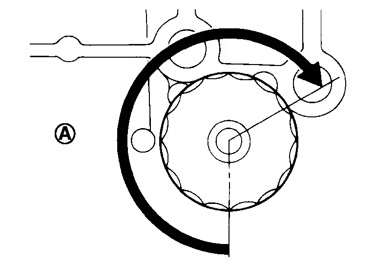
Using suitable tool, install new drain plug and tighten to the lock position in the direction shown.
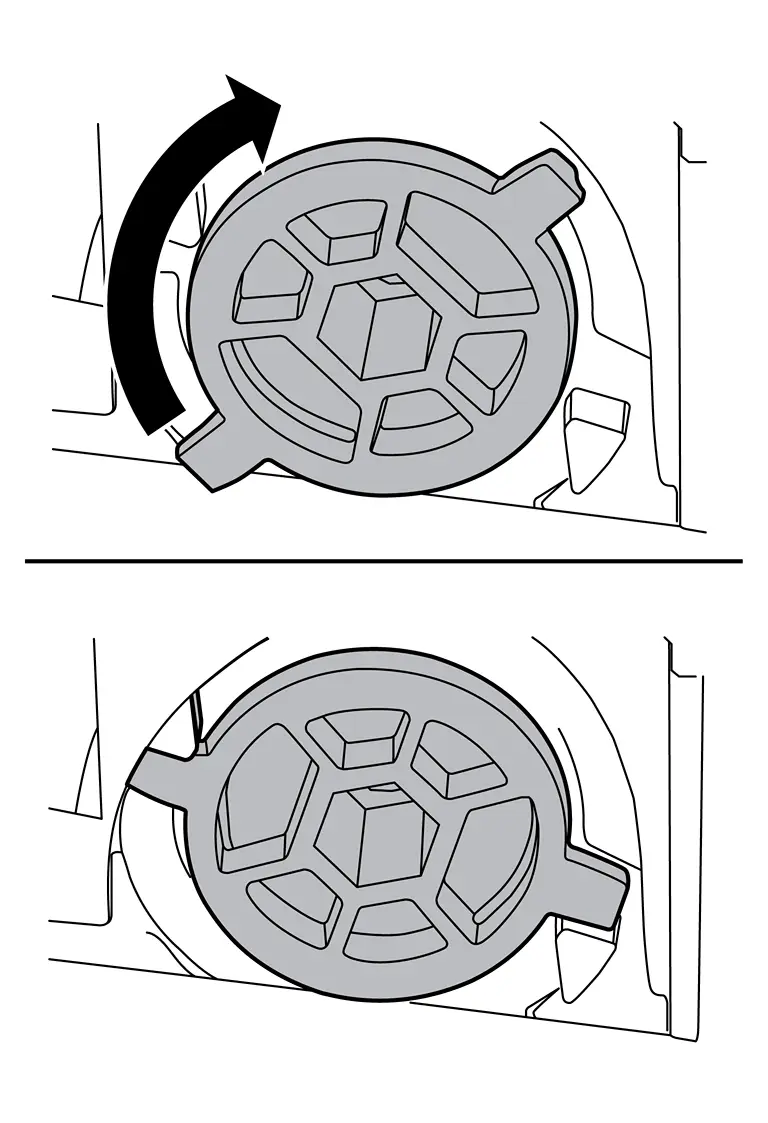
CAUTION:
-
Do not reuse drain plug.
-
Use genuine drain plug.
| Tightening torque | 3 N·m (0.31 kg-m, 27 in-lb | |
Refill with new engine oil.
Engine oil specification and viscosity: Refer to Fluids and Lubricants.
| Engine oil capacity | : Refer to Periodical Maintenance Specification. |
CAUTION:
-
The refill capacity depends on the engine oil temperature and drain time. Use these specifications for reference only.
-
Always use oil level gauge to determine the proper amount of engine oil in the engine.
Warm up engine and check area around drain plug and oil filter for engine oil leakage.
Stop engine and wait for 10 minutes.
Check the engine oil level. Refer to Inspection.
Install engine under cover. Refer to Removal and Installation.
CAUTION:
If engine oil replaced, perform "ENGINE OIL DATA RESET". Refer to Description.
Oil Filter
Removal and Installation
REMOVAL
-
Remove engine under cover. Refer to Removal and Installation.
-
Using oil filter wrench [SST: KV10115801], remove oil filter (1).
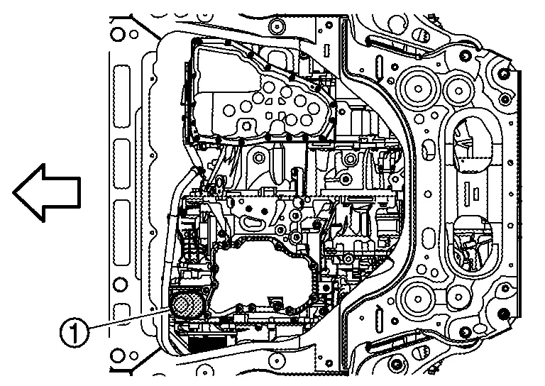

: Engine front NOTE:
It is recommended to use a Genuine Nissan oil filter or equivalent. The use of parts that do not meet or exceed Nissan specifications may cause damage to the Nissan Ariya vehicle, and have an effect on warranty coverage. Always check with the Parts Department for the latest parts information.
INSTALLATION
Remove foreign materials adhering to the oil filter installation surface.
Apply new engine oil to the oil seal contact surface of new oil filter.
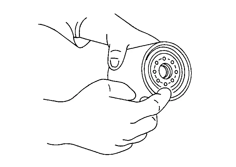
Screw oil filter manually until it touches the installation surface, then tighten it by 2/3 turn . Or tighten to specification.
| Oil filter: | |
 : 17.7 N·m (1.8 kg-m, 13 ft-lb) : 17.7 N·m (1.8 kg-m, 13 ft-lb) |
|
Install engine under cover. Refer to Removal and Installation.
CAUTION:
If engine oil replaced, perform "ENGINE OIL DATA RESET". Refer to Description.
Inspection
INSPECTION AFTER INSTALLATION
Check the engine oil level. Refer to Inspection.
Start the engine, and check there is no leakage of engine oil.
Stop the engine and wait for 10 minutes.
Check the engine oil level, and adjust the level. Refer to Inspection.
Kr15ddt :: Removal and Installation. Oil Cooler
Oil Cooler
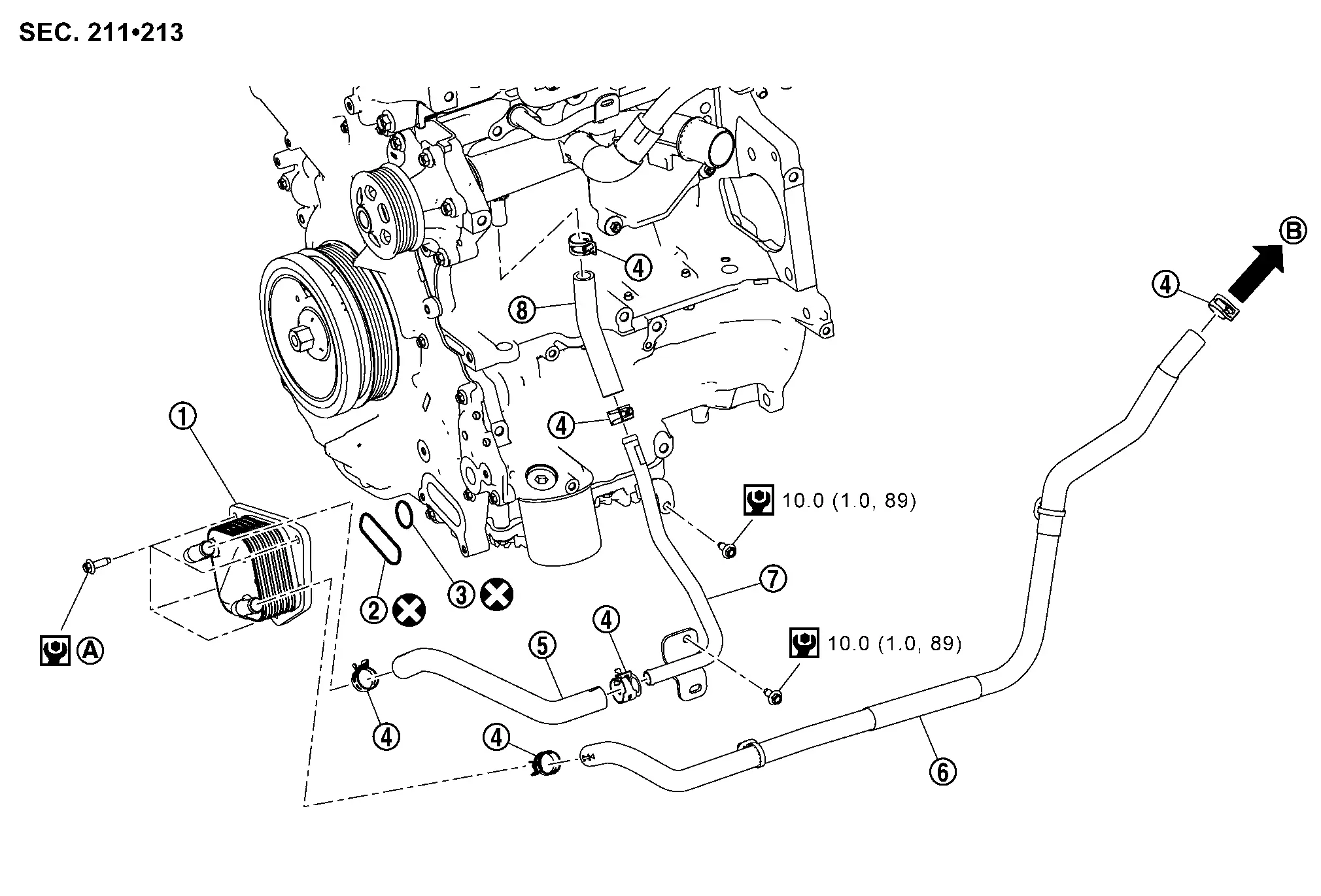
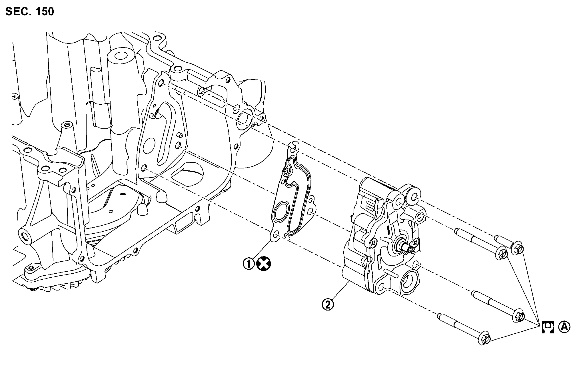
Exploded View
|
Oil cooler | |
Gasket | |
Gasket |
|
Clamp | |
Water hose 1 | |
Water hose 2 |
|
Water pipe | |
Water hose 3 | ||
|
Comply with the assembly procedure when tightening. Refer to Removal and Installation. | |
To CVT oil warmer. Refer to Exploded View. | ||
 |
: Always replace after every disassembly. | ||||
 |
: N·m (kg-m, in-lb) | ||||
Removal and Installation
REMOVAL
WARNING:
Be careful not to get burn yourself, as engine oil and engine coolant may be hot.
Drain engine oil. Refer to Draining.
Drain engine coolant from radiator and cylinder block. Refer to Draining and Setting.
NOTE:
Perform this step when removing water hoses.
Remove front spoiler. Refer to Removal and Installation.
Remove the front fender protector RH(front side), secure and ensure operation space. Refer to Removal and Installation.
Remove drive belt. Refer to Removal and Installation.
Disconnect all water hoses from oil cooler.
-
When removing oil cooler only, pinching water hoses near oil cooler to prevent engine coolant from spilling out.
-
Remaining engine coolant in piping will come out. Use a tray to collect it.
CAUTION:
Perform this step when the engine is cold.
Loosen oil cooler bolts in reverse of the sequence shown.
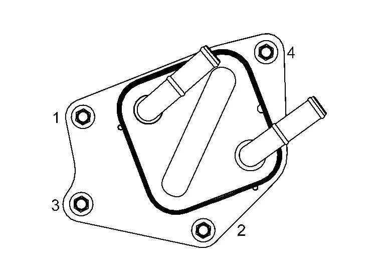
Remove oil cooler.
CAUTION:
Do not reuse gaskets.
Remove water pipe and water hose 3 if necessary.
INSTALLATION
INSTALLATION
Installation is in the reverse order of removal.
CAUTION:
Do not reuse gaskets.
NOTE:
Tighten oil cooler bolts to specified torque in the sequence as shown:
| Oil cooler bolts | : 10.0 N·m (1.0 kg-m, 89in-lb) |
Inspection
INSPECTION AFTER REMOVAL
Oil Cooler
Check oil cooler for cracks. Check oil cooler for clogging by blowing through engine coolant inlet. If necessary, replace oil cooler.
INSPECTION AFTER INSTALLATION
Check the engine oil level and the engine coolant level and add engine oil and engine coolant. Refer to Inspection and Inspection.
Start the engine, and check that there is no leakage of engine oil or engine coolant.
Stop the engine and wait for 10 minutes.
Check the engine oil level and the engine coolant level again. Refer to Inspection and Inspection.
Kr15ddt :: Unit Disassembly and Assembly. Oil Pump
Oil Pump
Exploded View
|
Gasket | |
Oil pump | ||
|
Comply with the assembly procedure when tightening. Refer to Removal and Installation | ||||
|
: Always replace after every disassembly. | ||||
|
: N·m (kg-m, ft-lb) | ||||
Removal and Installation
REMOVAL
Remove engine assembly. Refer to Removal and Installation.
Remove timing chain. Refer to Removal and Installation.
Remove oil pump chain. Refer to Removal and Installation.
Loosen oil pump bolts in reverse of the sequence shown and remove the oil pump.
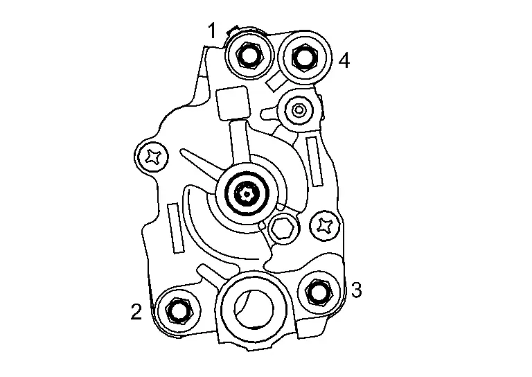
INSTALLATION
Note the following, and install in the reverse order of the removal.
CAUTION:
Do not reuse gasket.
-
Remove foreign materials adhering to the oil pump installation surface.
-
Tighten the oil pump bolts to the specified torque in the sequence shown.
Oil pump bolts : 25 N·m (2.6 kg-m, 18 ft-lb)
Kr15ddt :: Service Data and Specifications (sds). Service Data and Specifications (sds)
Service Data and Specifications (sds)
Periodical Maintenance Specification
ENGINE OIL CAPACITY (APPROXIMATE)
Unit:  (US qt, lmp qt)
| Drain and refill | With oil filter change | 4.7 (5, 4-1/8) |
| Without oil filter change | 4.6 (4-7/8, 4) | |
| Dry engine (Overhaul) | 5.6 (5-7/8, 4-7/8) | |
Engine Oil Pressure
ENGINE OIL PRESSURE
Unit: kPa (kg/cm2, psi)
| Engine speed | Approximate discharge pressure* |
| 600 rpm | More than 110 (1.122, 15.95) |
| 2,000 rpm | More than 340 (3.468, 49.3) |
*: Engine oil temperature at 80°C (176°F)
Other materials:
Dtc/circuit Diagnosis. Front Wiper Auto Stop Signal Circuit
Component Function Check
CHECK FRONT WIPER STOP POSITION SIGNAL
CONSULT
Select “FR WIPER STOP POSITION” in “Data monitor” mode of “IPDM E/R”.
Operate the front wiper.
With the front wiper operation, check the monitor status.
Monitor item Condition Monitor status
...
Main Line Between Dm Cam and Lane Circuit
Diagnosis Procedure
CHECK CONNECTOR
Turn the ignition switch OFF.
Disconnect the battery cable from the negative terminal.
Check the following terminals and connectors for damage, bend and loose connection (connector side and harness side).
Harness connector B41
Harness con ...
Symptom Diagnosis. Reverse Interlock Door Mirror Does Not Operate
Diagnosis Procedure
CHECK DTC
Check DTC for Electric Shift control module. Refer to DTC Index.
Is the inspection result normal?
YES>>
GO TO 2.
NO>>
Repair replace the malfunctioning parts.
CHECK DTC
Check DTC for BCM. Refer to DTC Index.
Is the inspection result normal?
YES& ...