Nissan Rogue (T33) 2021-Present Service Manual: Removal and Installation :: Mood Lamp (center Console Tray)
Exploded View
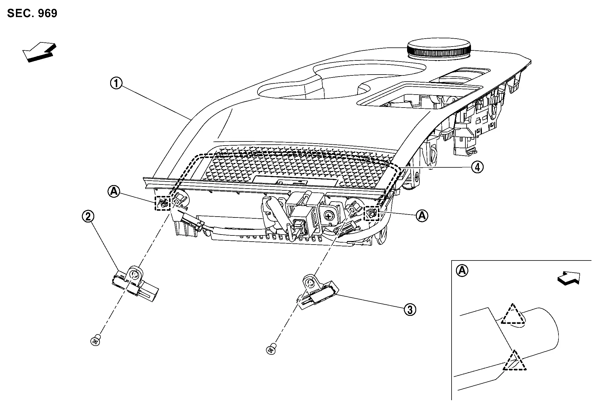
JAPAN PRODUCTION MODELS
 |
Console finisher assembly |  |
Mood lamp (center console tray) RH |  |
Mood lamp (center console tray) LH |
 |
Guide light | ||||
 |
: Pawl | ||||
| : Nissan Ariya Vehicle front | |||||
USA PRODUCTION MODELS
For exploded view of center console assembly. Refer to Exploded View.
Removal & Installation
JAPAN PRODUCTION MODELS
REMOVAL
CAUTION:
Disconnect the battery negative terminal or remove power circuit fuse when performing the operation for preventing electric leakage. Refer to Precautions for Removing Battery Terminal.
Remove console finisher assembly. Refer to Removal and Installation.
Remove mounting screws  .
.
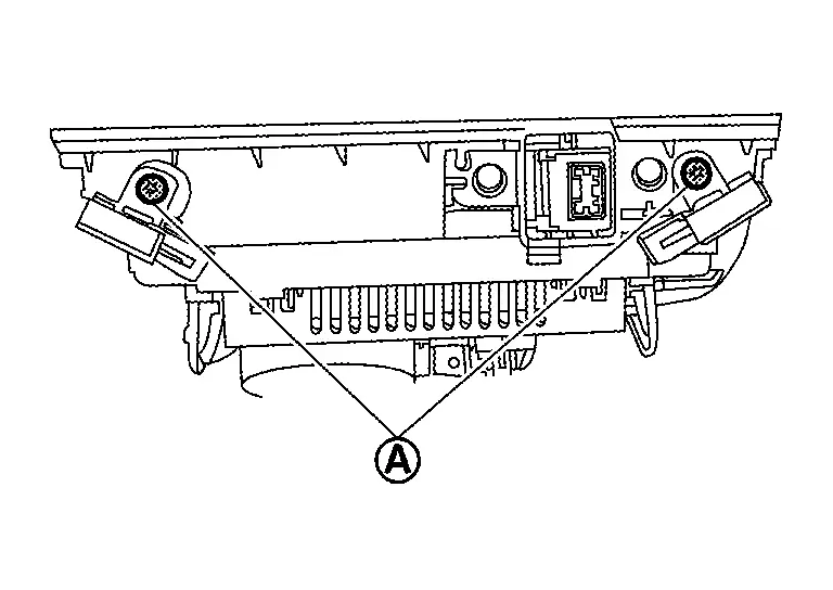
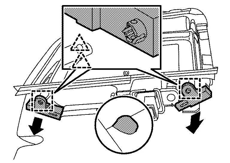
Disengage mood lamp (center console tray) fixing pawls, and then remove mood lamp (center console tray).
|
: Pawl |
INSTALLATION
Note the following item, and then install in the reverse order of removal.
CAUTION:
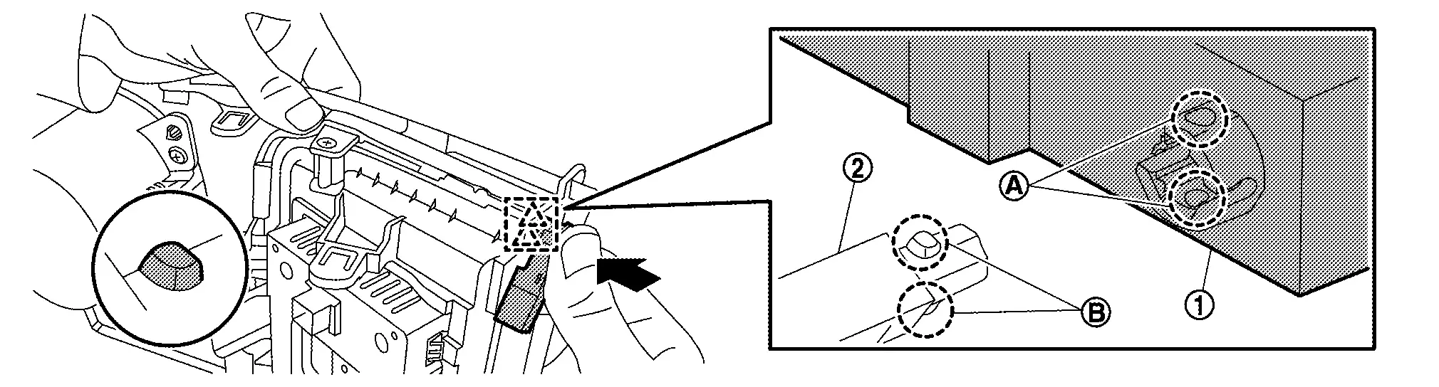
When installing, align connecting pawls  of guide light with point of mood lamp (center console tray) , and then install mood lamp (center console tray) onto guide light.
|
: Pawl |
Replacement
MOOD LAMP (CENTER CONSOLE TRAY)
JAPAN PRODUCTION MODELS
CAUTION:
-
Disconnect battery negative terminal or remove power circuit fuse when performing the operation for preventing electric leakage. Refer to Precautions for Removing Battery Terminal.
-
Replacement of a single part is not possible due to the adoption of LED. When replacement, replace mood lamp (center console tray) assembly as a set. Refer to Removal and Installation.
USA PRODUCTION MODELS
CAUTION:
Replacement of a single part is not possible due to the adoption of LED. When replacement, replace console finisher assembly as a set.
Other materials:
2wd. Preparation. Preparation
Preparation
Special Service Tool
Tool number
(TechMate No.)
Tool name Description
KV40104000
( – )
Hub lock nut wrench
a: 85 mm (3.35 in)
b: 65 mm (2.56 in)
Removing and Installing wheel hub lock nut.
KV40107300
( – )
Boot band crimping tool
Installing bo ...
Symptom Diagnosis. Squeak and Rattle Trouble Diagnoses
Work Flow
CUSTOMER INTERVIEWInterview
the customer if possible, to determine the conditions that exist when
the noise occurs. Use the Diagnostic Worksheet during the interview to
document the facts and conditions when the noise occurs and any customer
comments. Refer to Diagnostic Worksheet ...
Precaution. Precautions
PRECAUTIONS FOR SUPPLEMENTAL RESTRAINT SYSTEM (SRS) AIR BAG AND SEAT BELT PRE-TENSIONER
: Precautions
The Supplemental Restraint System such as “AIR BAG” and “SEAT BELT
PRE-TENSIONER”, used along with a front seat belt, helps to reduce the
risk or severity of injury t ...