
Nissan Rogue (T33) 2021-Present Service Manual: Removal and Installation :: Mood Lamp (center Console)
Exploded View
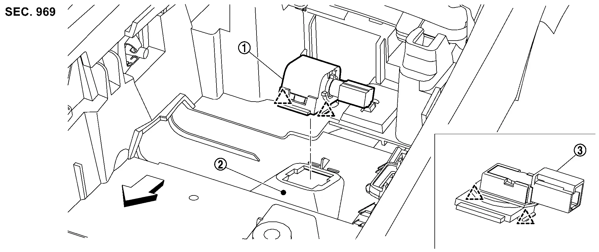
 |
Mood lamp (center console) assembly (Bulb type) |  |
Center console assembly |  |
Mood lamp (center console tray) assembly (LED type) |
 |
: Pawl | ||||
 |
: Nissan Ariya Vehicle front | ||||
Removal & Installation
REMOVAL
CAUTION:
Disconnect the battery negative terminal or remove power circuit fuse when performing the operation for preventing electric leakage. Refer to Precautions for Removing Battery Terminal.
Remove center console assembly. Refer to Removal and Installation.
Disconnect harness connector.
Disengage mood lamp (center console) assembly fixing pawls using a remover tool (A), and then remove mood lamp (center console) assembly.
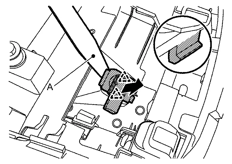
|
: Pawl |
INSTALLATION
Install in the reverse order of removal.
Replacement
MOOD LAMP (CENTER CONSOLE) (LED TYPE)
CAUTION:
-
Disconnect battery negative terminal or remove power circuit fuse when performing the operation for preventing electric leakage. Refer to Precautions for Removing Battery Terminal.
-
Replacement of a single part is not possible due to the adoption of LED. When replacement, replace mood lamp (center console) assembly as a set. Refer to Removal and Installation.
MOOD LAMP (CENTER CONSOLE) (BULB TYPE)
CAUTION:
-
Disconnect battery negative terminal or remove power circuit fuse when performing the operation for preventing electric leakage. Refer to Precautions for Removing Battery Terminal.
-
Replace mood lamp (center console) as a set. Refer to Removal & Installation.
Other materials:
P26a3 Multi-Way Control Valve Motor
DTC Description
DTC DETECTION LOGICNOTE:
If DTC P26A3 is displayed with DTC P26A5, P26A6, and/or
P26A7 first perform the trouble diagnosis for DTC P26A5, P26A6, and/or
P26A7. Refer to DTC Index.
DTC
CONSULT screen terms
(Trouble diagnosis content) DTC detection condition
P26A3
00
...
Basic Inspection. Additional Service When Replacing Driver Seat Control Unit
Description
Each function is reset to the following condition when the driver
seat control unit is replaced. For details, refer to Work Procedure. Function Condition Procedure
Memory (Seat, mirror)
Erased
Perform memory storing
Log-in*1
Erased
Perform log-in storing
Inte ...
Back-Up Lamp Circuit
Component Function Check
CHECK BACK-UP LAMP OPERATION
Start the engine.
With operating the shift selector, check that the back-up lamp is turned ON.
Shift selector position: R range
: Back-up lamp ON
Shift selector position: Other than above
: Back-up lamp OFF
Is th ...