Nissan Rogue (T33) 2021-Present Service Manual: Cylinder Head
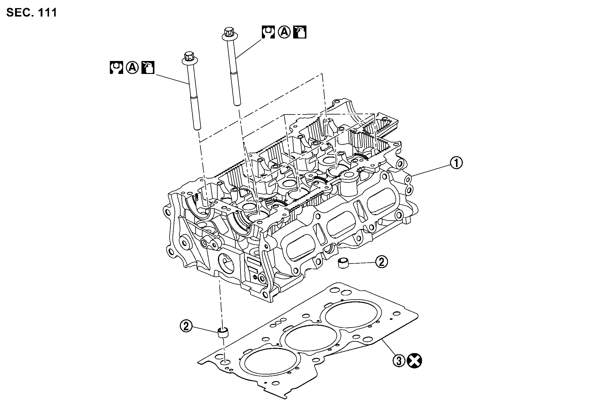
Exploded View
REMOVAL
 |
Cylinder head assembly |  |
Knock pin |  |
Cylinder head gasket |
 |
Comply with the assembly procedure when tightening. Refer to Removal and Installation. | ||||
 |
: N·m (kg-m, ft-lb) | ||||
 |
: Always replace after every disassembly. | ||||
 |
: Should be lubricated with oil. | ||||
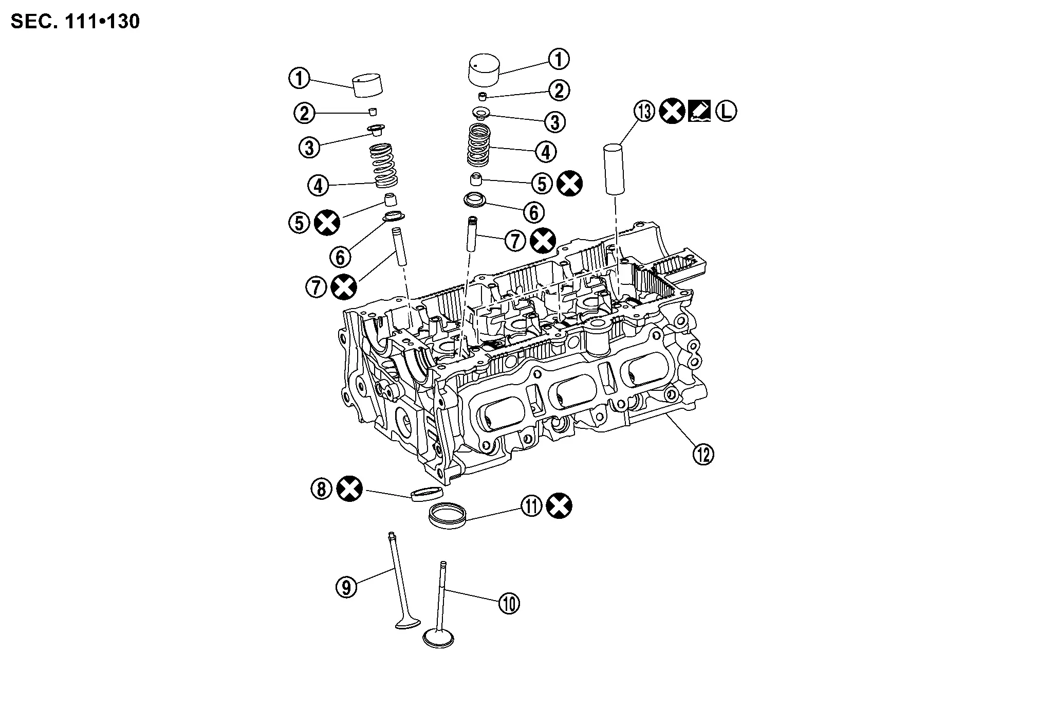
DISASSEMBLY
|
Valve lifter | |
Valve collet | |
Valve spring retainer |
 |
Valve spring |  |
Valve oil seal |  |
Valve spring seat |
 |
Valve guide |  |
Valve seat (EXH) |  |
Valve (EXH) |
 |
Valve (INT) |  |
Valve seat (INT) |  |
Cylinder head |
 |
Spark plug tube | ||||
  |
: Apply thread locking sealant. | ||||
|
: Always replace after every disassembly. | ||||
Removal and Installation
REMOVAL
Remove three way catalyst. Refer to Removal and Installation.
Remove turbocharger. Refer to Removal and Installation.
Remove EGR cooler. Refer to Removal and Installation.
Remove intake manifold. Refer to Removal and Installation.
Remove high pressure fuel pump. Refer to Removal and Installation.
Remove fuel injector. Refer to Removal and Installation.
For models without ProPILOT Assist 2.1, remove vacuum pump. Refer to Removal and Installation.
For models with ProPILOT Assist 2.1, remove the rear camshaft bracket. Refer to Exploded View.
Remove camshaft. Refer to Removal and Installation.
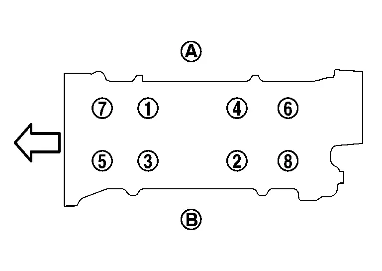
Loosen cylinder head bolts in reverse of the sequence shown and remove the cylinder head.
|
: Exhaust side |
 |
: Intake side |
 |
: Engine front |
Remove cylinder head gasket.
CAUTION:
Do not reuse cylinder head gasket.
INSTALLATION
Install cylinder head gasket.
CAUTION:
Do not reuse cylinder head gasket.
Install cylinder head and tighten cylinder head bolts using the following procedure:
CAUTION:
If cylinder head bolts are reused, check their outer diameters before installation. Refer to
Apply new engine oil to threads and seating surface of cylinder head bolts. Tighten all cylinder head bolts to the specified torque in the sequence shown.
| Cylinder head bolts | : 40.0 N·m (4.1 kg-m, 30 ft-lb) |
|
: Exhaust side |
|
: Intake side |
|
: Engine front |
CAUTION:
Check and confirm the tightening angle by using a angle wrench [SST:KV10112100 (BT8653-A)] (A) or protractor. Do not judge by visual inspection without the Tool.
| Tightening angle | : 110° |
CAUTION:
Check and confirm the tightening angle by using a angle wrench [SST:KV10112100 (BT8653-A)] (A) or protractor. Do not judge by visual inspection without the Tool.
| Tightening angle | : 110° |
Installation of the remaining components is in the reverse order of removal.
Disassembly and Assembly
DISASSEMBLY
Remove spark plug. Refer to Removal and Installation.
Remove valve lifter.
-
Identify installation positions, and store them without mixing them up.
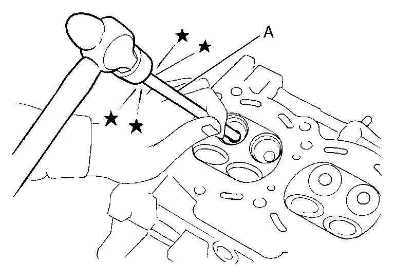
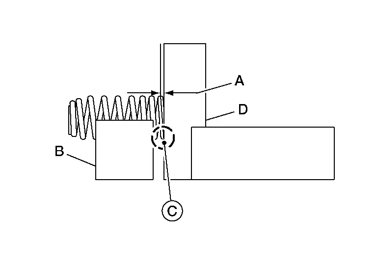
Compress the valve spring with suitable tool (A), (B) and (C) and remove the valve collet with a suitable magnetic tool.
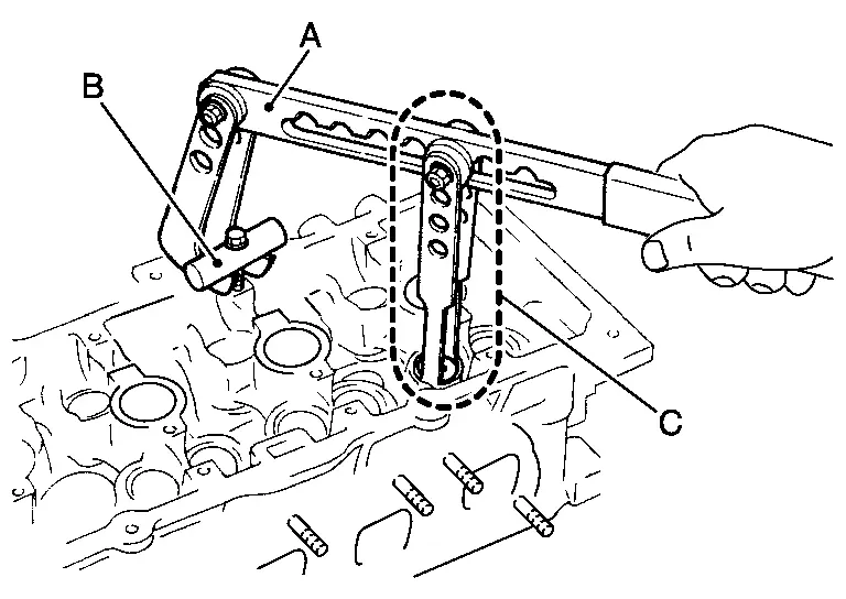
CAUTION:
-
Be careful not to damage valve lifter holes.
-
The center of the suitable tool (A) and valve spring retainer
must be aligned.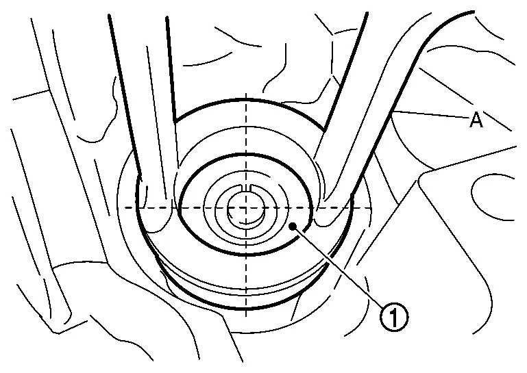
Remove valve spring retainer and valve spring (with valve spring seat).
CAUTION:
Do not remove valve spring seat from valve spring.
Push valve into combustion chamber side and remove valve.
-
Identify installation positions, and store them without mixing them up.
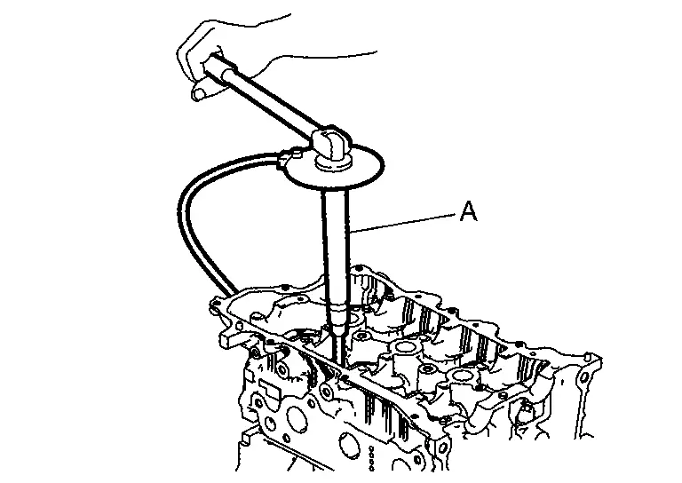
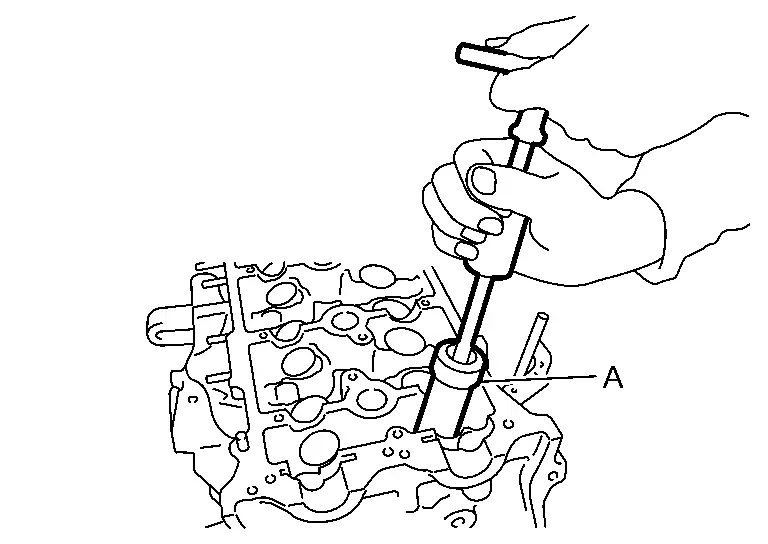
Remove valve oil seal with valve oil seal puller (A).
When valve seat must be replaced:
-
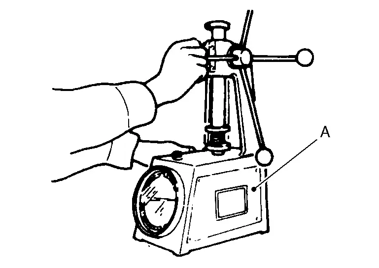
Bore out old valve seat until it collapses. Boring should not continue beyond the bottom face of the valve seat recess in cylinder head. Set the machine depth stop to ensure this. Refer to Cylinder Head.
CAUTION:
Do not bore excessively to prevent cylinder head from scratching.
When valve guide must be replaced:To remove valve guide, heat
cylinder head to 110 to 130°C (230 to 266°F) by soaking in heated oil .
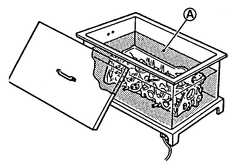
CAUTION:
Cylinder head contains heat, wear protective equipment to avoid getting burned.
ASSEMBLY
When valve guide is removed, install it.
CAUTION:
Replace with oversize [0.2 mm (0.008 in)] valve guide.
Ream cylinder head valve guide hole with a suitable tool (A).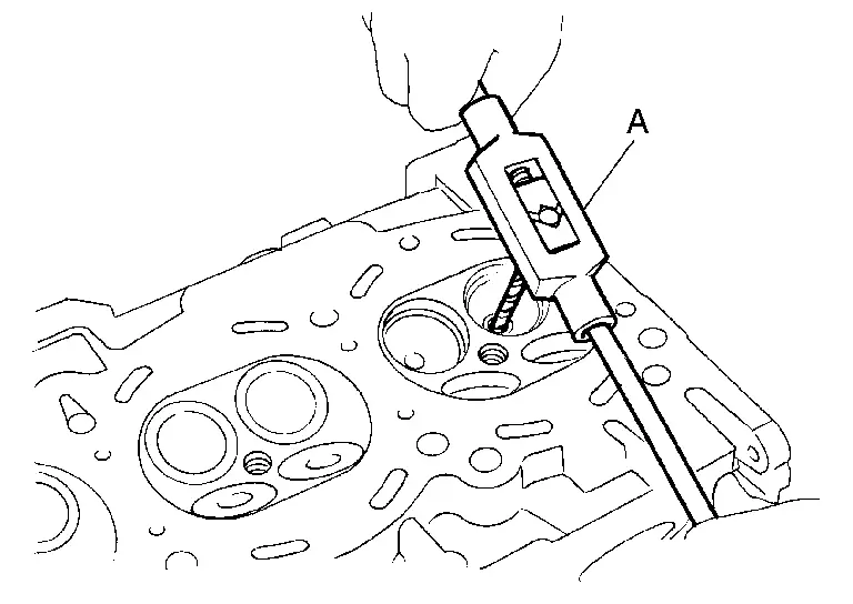
| For service parts: Oversize [0.2 mm (0.008 in)] | ||
| Refer to Cylinder Head. | ||
.
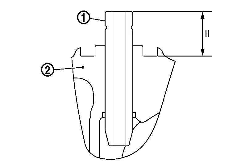
from camshaft side to dimensions as shown.
CAUTION:
Cylinder head contains heat, wear protective equipment to avoid getting burned.
| Projection (H) | : Refer to Cylinder Head. | |
|
: Cylinder head |
| Standard | : Refer to Cylinder Head |
When valve seat is removed, install it.
CAUTION:
Replace with oversize [0.5 mm (0.020 in)] valve seat.
Ream cylinder head recess diameter for service valve seat .
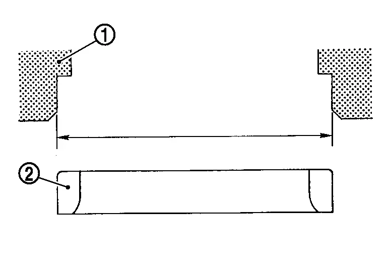
| For service parts: Oversize [0.5 mm (0.020 in)] | ||
| Refer to Cylinder Head. | ||
-
Be sure to ream in circles concentric to the valve guide center.
This will enable valve seat to fit correctly.
.
CAUTION:
Cylinder head contains heat, wear protective equipment to avoid getting burned.
Using suitable tool (A), finish valve seat to the specified dimensions. For dimensions, refer to Cylinder Head.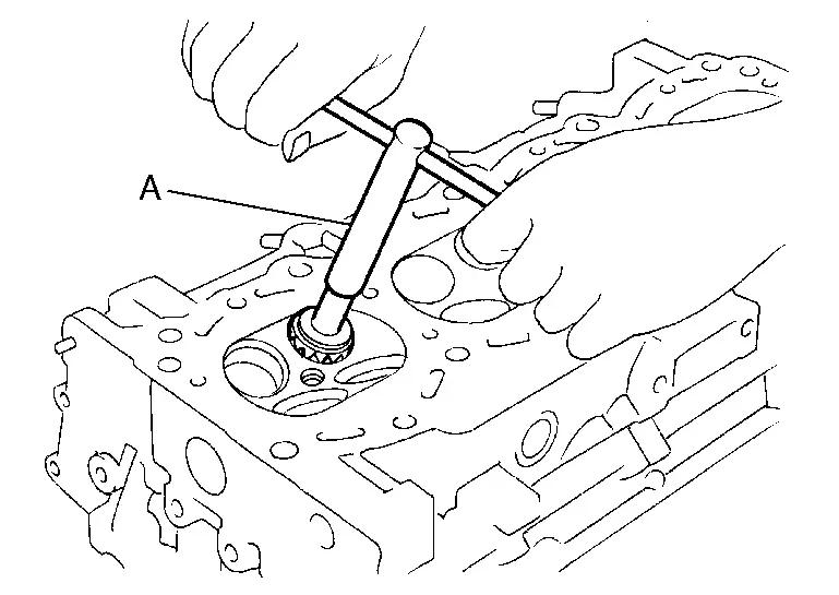
CAUTION:
When using suitable tool, firmly grip the suitable tool handle with both hands. Then, press on the contacting surface all around the circumference to cut in a single drive. Improper pressure with the cutter or cutting many different times may result in stage valve seat.
Using compound, grind to adjust valve fitting. Check again for normal contact. Refer to Inspection.Install valve oil seal using suitable tool (A) to the specified height (H).
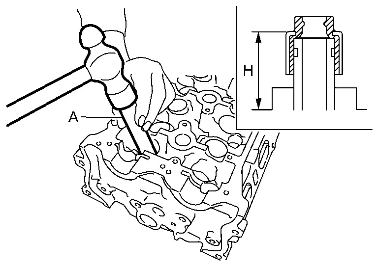
 NOTE:
NOTE:
-
Dimension is height that is measured before installing valve spring (with valve spring seat).
-
Valve oil seals are different for intake and exhaust, make sure to instal valve oil seals in correct positions.
| Height (H) | INT | : 15.1 - 15.7 mm (0.594 - 0.618 in) |
| EXH | : 16.6 - 17.2 mm (0.654 - 0.677 in) | |
| Valve oil seal color | Intake | : Gray |
| Exhaust | : Green |
Install valve.
-
Install larger diameter to intake side.
Install valve spring (with valve spring seat).
-
Install smaller pitch (valve spring seat side) to cylinder head side
.
CAUTION:
Do not remove valve spring seat
 from valve spring.
 -
Confirm identification color
of valve spring.Intake : Yellow – Green Exhaust : Blue
Install valve spring retainer.
Install valve collet.
-
Compress the valve spring with suitable tool (A), (B) and (C) and install the valve collet with a suitable magnetic tool.
CAUTION:
-
Be careful not to damage valve lifter holes.
-
The center of the suitable tool (A) and valve spring retainer
must be aligned.
-
-
Tap valve stem edge lightly with a plastic hammer after installation to check its installed condition.
Install valve lifter.
-
Install it in the original position.
Install spark plug.
Inspection
INSPECTION AFTER REMOVAL
Cylinder Head Bolts Outer Diameter
-
Cylinder head bolts are tightened by plastic zone tightening method. Whenever the size difference between (A) and (B) exceeds the limit, replace them with a new one.
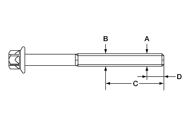
Limit [(A) – (B)] : 0.15 mm (0.0059 in) Dimension (C) : 45 mm (1.7717 in) Dimension (D) : 11 mm (0.4331 in) -
If reduction of outer diameter appears in a position other than (B), use it as (B) point.
Cylinder Head Distortion
NOTE:
When performing this inspection, cylinder block distortion should be also checked.
Wipe off engine oil and remove water scale (like deposit), gasket, sealant, carbon, etc. with a suitable tool.
CAUTION:
Do not allow gasket debris to enter passages for engine oil or water.
At each of several locations on bottom surface of cylinder head, measure the distortion in six directions using suitable tool (A) and suitable tool (B).
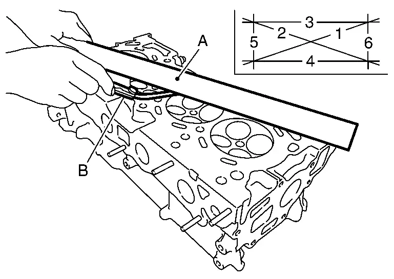
| Limit | : Refer to Cylinder Head. |
-
If it exceeds the limit, replace cylinder head.
Cylinder Block Top Surface Distortion
-
Using a suitable tool, remove gasket on the cylinder block surface, and also remove engine oil, scale, carbon, or other contamination.
CAUTION:
Be careful not to allow gasket particles to enter engine oil or engine coolant passages.
-
Measure the distortion on the cylinder block upper face at different points in six different directions with a suitable tool (A) and suitable tool (B).
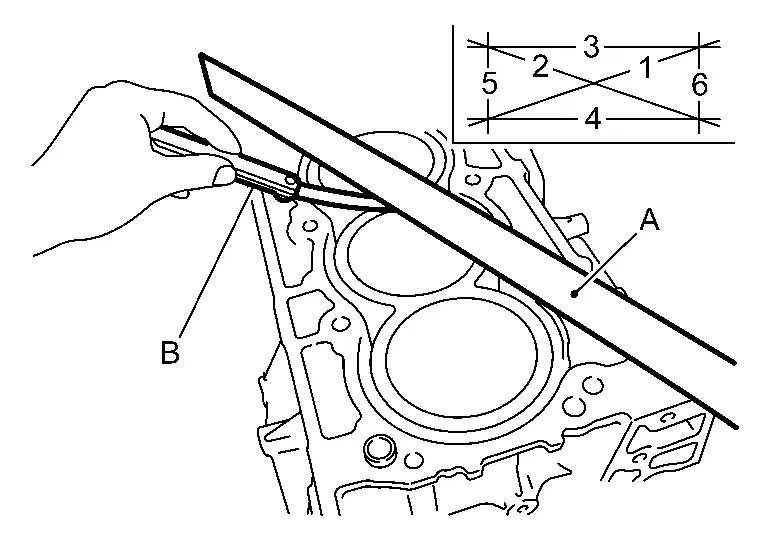
Limit 0.03 mm (0.001 in) -
If it exceeds the limit, replace cylinder block.
INSPECTION AFTER DISASSEMBLY
VALVE DIMENSIONS
-
Check the dimensions of each valve. For the dimensions, refer to Cylinder Head.
-
If dimensions are out of the standard, replace valve and check valve seat contact. Refer to "VALVE SEAT CONTACT".
VALVE GUIDE CLEARANCE
Valve Stem Diameter
-
Measure the diameter of valve stem with a suitable tool (B).
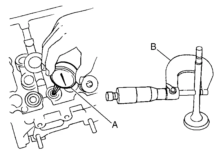
Standard : Refer to Cylinder Head.
Valve Guide Inner Diameter
-
Measure the inner diameter of valve guide with a suitable tool (A).
Standard : Refer to Cylinder Head.
Valve Guide Clearance
-
(Valve guide clearance) = (Valve guide inner diameter) – (Valve stem diameter)
Standard and Limit : Refer to Cylinder Head. -
If the calculated value exceeds the limit, replace valve and/or valve guide. When valve guide must be replaced, refer to Disassembly & Assembly.
VALVE SEAT CONTACT
-
After confirming that the dimensions of valve guides and valves are within the specifications, perform this procedure.
-
Apply prussian blue (or white lead) onto contacting surface of valve seat to check the condition of the valve contact on the surface.
-
Check if the contact area band is continuous all around the circumference.
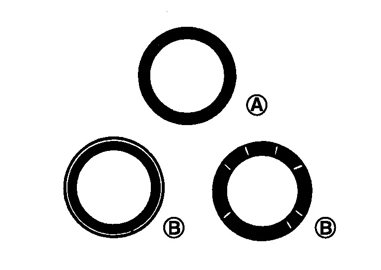
: OK -
If not, grind to adjust valve fitting and check again. If the contacting surface still has “NG” conditions
even after the recheck, replace valve seat. Refer to Disassembly & Assembly.
VALVE SPRING SQUARENESS
-
Set a suitable tool (D) along the side of valve spring and rotate spring. Measure the maximum clearance (A) between the top of spring and suitable tool.
B : Suitable tool : Contact area Limit : Refer to Cylinder Head -
If it exceeds the limit, replace valve spring.
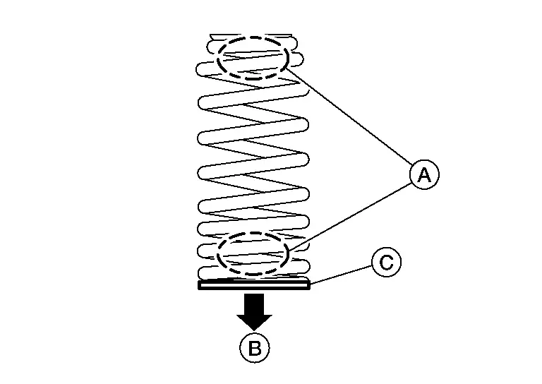
VALVE SPRING DIMENSIONS AND VALVE SPRING PRESSURE LOAD
-
Check valve spring pressure (A) with valve spring seat installed at the specified spring height.
CAUTION:
Do not remove valve spring seat from valve spring.
NOTE:
Before measuring valve spring pressure, compress each spring to specified solid height for intake and exhaust valve springs.
Valve spring (EXH) : 28.86 mm (1.1362 in) Valve spring (INT) : 27.1 mm (1.0669 in) Standard : Refer to Cylinder Head -
If the installation load or load with valve open is out of the standard, replace valve spring (with valve spring seat).
INSPECTION AFTER INSTALLATION
Inspection for Leakage
The following are procedures for checking fluid leakage, lubricant leakage, and exhaust gas leakage.
-
Before starting engine, check oil/fluid levels including engine coolant and engine oil. If less than required quantity, fill to the specified level. Refer to Fluids and Lubricants.
-
Use procedure below to check for fuel leakage:
-
Turn ignition switch “ON” (with engine stopped). With fuel pressure applied to fuel piping, check for fuel leakage at connection points.
-
Start engine. With engine speed increased, check again for fuel leakage at connection points.
-
-
Run engine to check for unusual noise and vibration.
NOTE:
If hydraulic pressure inside timing chain tensioner drops after removal/installation, slack in guide may generate a pounding noise during and just after the engine start. However, this does not indicate an unusualness. Noise will stop after hydraulic pressure rises.
-
Warm up engine thoroughly to check that there is no leakage of fuel, or any oil/fluids including engine oil and engine coolant.
-
Bleed air from lines and hoses of applicable lines, such as in cooling system.
-
After cooling down engine, again check oil/fluid levels including engine oil and engine coolant. Refill to the specified level, if necessary.
Summary of the inspection items: Items Before starting engine Engine running After engine stopped Engine coolant Level Leakage Level Engine oil Level Leakage Level Transmission / transaxle fluid AT & CVT Models Leakage Level / Leakage Leakage MT Models Level / Leakage Leakage Level / Leakage Other oils and fluids* Level Leakage Level Fuel Leakage Leakage Leakage Exhaust gases — Leakage — *: Power steering fluid, brake fluid, etc.
Other materials:
If your vehicle overheats
WARNING
Never continue driving if your vehicle overheats — this can lead to engine failure or even a vehicle fire.
Never open the hood if steam is coming out.
Never remove the radiator or coolant reservoir cap when the engine is hot. Pressurized coolant can spray out and cause serious ...
Accelerator Pedal Position Sensor
Component Inspection
CHECK ACCELERATOR PEDAL POSITION SENSOR
Turn ignition switch OFF.
Reconnect all harness connectors disconnected.
Turn ignition switch ON.
Check the voltage between ECM harness connector terminals as per the following condition.
ECM Condition
Voltage
(A ...
B2600-42 Configuration Error
DTC Description
DTC DETECTION LOGIC DTC No. CONSULT screen terms DTC detected condition
B2600-42
Configuration error
Diagnosis condition
After the ignition switch OFF, wait for 1 minutes or more
When ignition switch is ON.
Signal (terminal)
—
Threshold
...