
Nissan Rogue (T33) 2021-Present Service Manual: Rear Oil Seal
Removal and Installation
REMOVAL
Remove drive plate. Refer to Removal and Installation.
Remove rear oil seal with a suitable tool.
CAUTION:
-
Do not damage crankshaft or cylinder block.
-
Do not reuse rear oil seal.
INSTALLATION
Install rear oil seal so that each seal lip is oriented as shown.
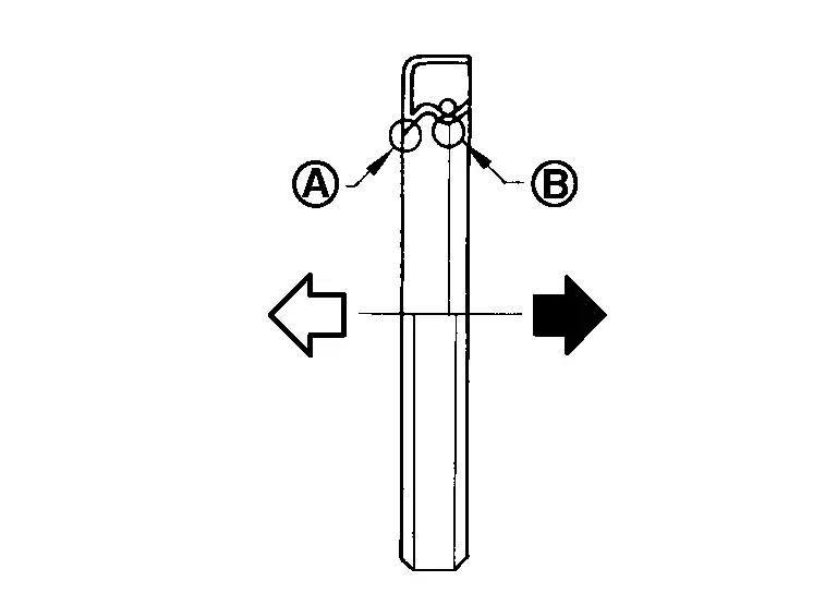
 |
: Dust seal lip |
 |
: Oil seal lip |
 |
: Engine outside |
 |
: Engine inside |
-
Press-fit rear oil seal with a suitable drift (A) outer diameter 115 mm (4.53 in) and inner diameter 90 mm (3.54 in).
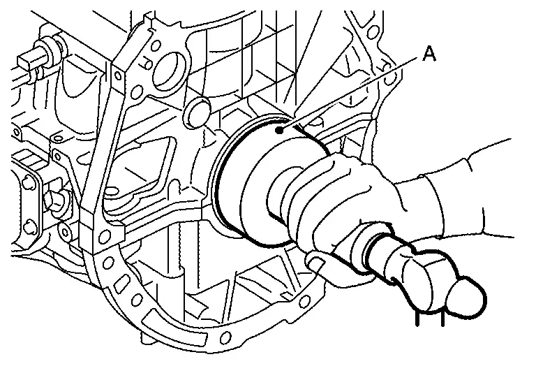
CAUTION:
-
Do not damage crankshaft or cylinder block.
-
Press-fit rear oil seal straight to avoid causing burrs or tilting.
-
Do not touch grease applied onto oil seal lip.
-
-
Press in rear oil seal
 to the position as shown.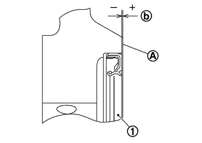
Dimension 
: (–0.3) - (+0.5) mm [(–0.012) - (+0.020) in] : Rear end surface of cylinder block
Installation of the remaining components is in the reverse order of removal.
Other materials:
Engine Cover
Exploded View
Engine cover
Stud
Bracket
Bracket
: N·m (kg-m, in-lb)
Removal and Installation
REMOVALRemove the engine cover by pulling it off in an upwards direction.CAUTION:
Never damage or scratch engine cover when installing or ...
Basic information
CAMERA button
WARNING
Failure to follow the warnings and instructions for proper use of the Intelligent Around View Monitor system on your Nissan Rogue could result in serious injury or death.
The Intelligent Around View Monitor is a convenience system and must not replace safe driving pract ...
C1f05-49 Front Camera Unit
Without Propilot Assist 2.1
DTC Description
DTC DETECTION LOGIC DTC
CONSULT screen terms
(Trouble diagnosis content) DTC detection condition
C1F05
49
Front camera unit
(Front camera unit)
Diagnosis condition
When engine is running
Signal (terminal)
—
T ...