Nissan Rogue (T33) 2021-Present Service Manual: B24a4-11 Intake Sensor
DTC Description
DTC DETECTION LOGIC
| DTC No. |
CONSULT screen terms (Trouble diagnosis content) | DTC detection condition | |
|---|---|---|---|
| B24A4-11 |
INTAKE SENSOR (Intake sensor) |
Diagnosis condition | Ignition switch ON |
| Signal (Terminal) | Intake sensor signal | ||
| Threshold | The intake sensor recognition temperature is too high [more than 100°C (212°F)] | ||
| Diagnosis delay time | 2 second or more | ||
POSSIBLE CAUSE
-
Intake sensor
-
A/C amp.
-
Harness or connectors (the sensor circuit is shorted to ground)
FAIL-SAFE
—
DTC CONFIRMATION PROCEDURE
PERFORM DTC CONFIRMATION PROCEDURE
 CONSULT
-
Ignition switch ON.
-
Select “Self diagnosis result” mode of “HVAC”.
-
Check DTC.
Is DTC detected?
YES>>Refer to Diagnosis Procedure.
NO-1>>To check malfunction symptom before repair: Refer to Intermittent Incident.
NO-2>>Confirmation after repair: Inspection End.
DTC Diagnosis Procedure
CHECK INTAKE SENSOR SIGNAL
-
Ignition switch ON.
-
Check voltage between A/C amp. harness connector.
A/C amp. Voltage Connector Terminal (+) (-) M54 23 26 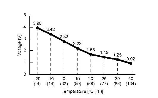
Is the inspection result normal?
YES>>Replace A/C amp. Refer to Removal and Installation.
NO>>GO TO 2.
CHECK INTAKE SENSOR POWER SUPPLY
-
Ignition switch OFF.
-
Disconnect intake sensor connector.
-
Ignition switch ON.
-
Check voltage between intake sensor harness connector and ground.
(+) (-) Voltage
(Approx.)Intake sensor Connector Terminal M135 1 Ground 5 V
Is the inspection result normal?
YES>>GO TO 3.
NO>>GO TO 4.
CHECK INTAKE SENSOR
Check intake sensor. Refer to Component Inspection.
Is the inspection result normal?
YES>>Replace A/C amp. Refer to Removal and Installation.
NO>>Replace intake sensor. Refer to Removal and Installation.
CHECK INTAKE SENSOR POWER SUPPLY CIRCUIT FOR SHORT
-
Ignition switch OFF.
-
Disconnect A/C amp. connector.
-
Check continuity between intake sensor harness connector and ground.
Intake sensor (—) Continuity Connector Terminal M135 1 Ground No
Is the inspection result normal?
YES>>Replace A/C amp. Refer to Removal and Installation.
NO>>Repair harness or connector.
Component Inspection
CHECK INTAKE SENSOR
-
Ignition switch OFF.
-
Remove intake sensor. Refer to Removal and Installation.
-
Check resistance between intake sensor terminals. Refer to applicable table for the normal value.
Terminal Condition Resistance: kΩ Temperature: °C (°F) 1 2 −20 (−4) 23.60 −10 (14) 13.46 0 (32) 8.00 10 (50) 4.93 20 (68) 3.14 25 (77) 2.54 30 (86) 2.06 40 (104) 1.39
Is the inspection result normal?
YES>>Inspection End.
NO>>Replace intake sensor. Refer to Removal and Installation.
Other materials:
Steering Switch Signal B Circuit
Component Function Check
CHECK COMBINATION METER INPUT SIGNAL
CONSULT
Ignition switch ON.
Select “Steering switch input” in “Data monitor” mode of “M&A”.
Check that the function operates normally according to the following conditions:
Condition Value
CONTRO ...
Driver Assistance System. Preparation. Preparation
Preparation
Special Service Tools
The actual shape of the tools may differ from those illustrated here.
Tool number
(TechMate No.)
Tool name Description
  —
(NI-46534)
Trim Tool Set
Removing trim components
—
(1–20–2851–1)
ICC alignment kit*
...
System Description. Component Parts
Body Control System
Component Parts Location
A.
Underneath instrument panel LH (view with lower instrument panel finisher removed)
No. Component Function
1.
BCM
Refer to System Description.
Power Consumption Control System
Component Parts Location
No. Component Functio ...