Nissan Rogue (T33) 2021-Present Service Manual: System Description :: Component Parts
Body Control System
Component Parts Location
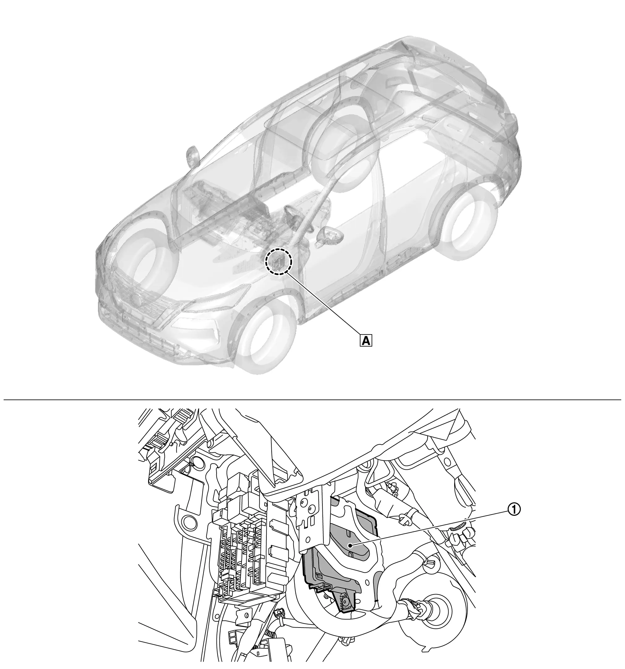
| A. | Underneath instrument panel LH (view with lower instrument panel finisher removed) |
| No. | Component | Function |
|---|---|---|
| 1. | BCM | Refer to System Description. |
Power Consumption Control System
Component Parts Location
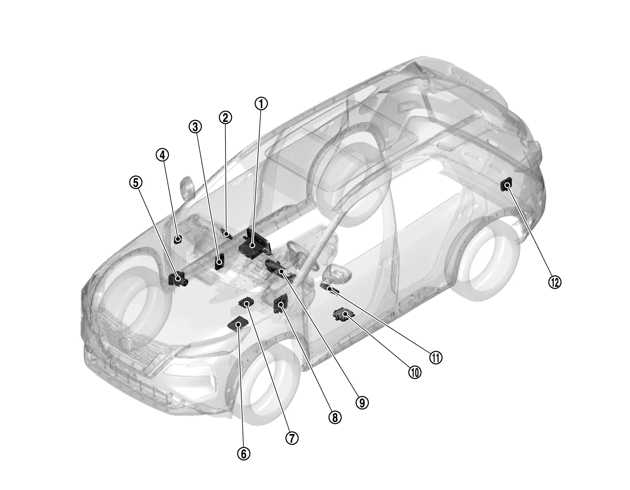
| No. | Component | Function |
|---|---|---|
| 1. | AV control unit | Refer to AV Control Unit (8" color display) or AV Control Unit (12.3" color display) for detailed component location. |
| 2. | Intelligent Key unit | Refer to Intelligent Key Unit for detailed component location. |
| 3. | TCU (if so equipped) | Refer to TCU (8" color display) or TCU (12.3" color display) for detailed component location. |
| 4. | Chassis control module (if so equipped) | Refer to Chassis Control Module for detailed component location. |
| 5. | ABS actuator and electric unit (control unit) | Refer to ABS Actuator and Electric Unit (Control Unit) for detailed component location. |
| 6. | IPDM E/R | Refer to System Description. |
| 7. | Electric shift control module | Refer to Electric Shift Control Module for detailed component location. |
| 8. | BCM | Refer to System Description. |
| 9. | Combination meter | Refer to Combination Meter (type A) or Combination Meter (type B) for detailed component location. |
| 10. | BOSE speaker amp. (if so equipped) | Refer to Bose Speaker Amp. for detailed component location. |
| 11. | Driver seat control unit (if so equipped) | Refer to Driver Seat Control Unit for detailed component location. |
| 12. | Automatic back door control unit (if so equipped) | Refer to Automatic Back Door Control Unit for detailed component location. |
Other materials:
Symptom Diagnosis. Door Does Not Lock/unlock with Door Request Switch and Intelligent Key
Description
All doors do not lock/unlock using door request switch.SYMPTOM TABLE (BOTH INTELLIGENT KEYS HAVE THE SAME SYMPTOMS) Door lock operation (remote keyless entry)
Door lock operation (request switch of front/rear/back door) or
trunk/back door open operation (opener switch of trunk/back ...
B24a1-16 A/c Auto Amp. Power Supply
DTC Description
DTC DETECTION LOGIC DTC No.
CONSULT screen terms
(Trouble diagnosis content) DTC detection condition
B24A1-16
A/C AUTO AMP. POWER SUPPLY
(Air conditioning automatic amplifier power supply)
Diagnosis condition
Ignition switch ON
Signal (Terminal)
Accessory p ...
Dtc/circuit Diagnosis. U1327-52 Mac Key Update
DTC Description
DTC DETECTION LOGIC DTC No.
CONSULT screen items
(Trouble diagnosis content) DTC Detection Condition
U1327-52
MAC key update
(Message authentication code key update)
Diagnosis condition
-
Signal (terminal)
-
Threshold
MAC key writing is incomplete. ...