Nissan Rogue (T33) 2021-Present Service Manual: Steering Switch Signal B Circuit
Component Function Check
CHECK COMBINATION METER INPUT SIGNAL
 CONSULT
-
Ignition switch ON.
-
Select “Steering switch input” in “Data monitor” mode of “M&A”.
-
Check that the function operates normally according to the following conditions:
| Condition | Value |
|---|---|
| CONTROL switch is pressed | SW1 |
| Jog dial is rotated to upward | SW2 |
| Jog dial is rotated to downward | SW3 |
| OK switch is pressed | SW4 |
| LEFT/BACK switch is pressed | SW5 |
| RIGHT switch is pressed | SW6 |
| VOL DOWN switch is pressed | SW7 |
| VOL UP switch is pressed | SW8 |
| TEL END switch is pressed | SW9 |
| VR/TEL switch is pressed | SW10 |
| SEEK DOWN switch is pressed | SW11 |
| SEEK UP switch is pressed | SW12 |
| Other than above | NO INPUT |
Is the inspection result normal?
YES>>Inspection End.
NO>>Refer to Diagnosis Procedure.
Diagnosis Procedure
CHECK STEERING SWITCH SIGNAL B CIRCUIT
-
Disconnect combination meter harness connector and spiral cable harness connector.
-
Check continuity between combination meter harness connector and spiral cable harness connector.
Combination meter Spiral cable Continuity Connector Terminal Connector Terminal M73 (U.S.A. production)
M77 (Japan production)23 M30 9 Yes -
Check continuity between combination meter harness connector and ground.
Combination meter Ground Continuity Connector Terminal M73 (U.S.A. production)
M77 (Japan production)23 No
Is the inspection result normal?
YES>>GO TO 2.
NO>>Repair harness or connector.
CHECK STEERING SWITCH SIGNAL GROUND CIRCUIT
-
Check continuity between combination meter harness connector and spiral cable harness connector.
Combination meter Spiral cable Continuity Connector Terminal Connector Terminal M73 (U.S.A. production)
M77 (Japan production)34 M30 11 Yes -
Check continuity between combination meter harness connector and ground.
Combination meter Ground Continuity Connector Terminal M73 (U.S.A. production)
M77 (Japan production)34 No
Is the inspection result normal?
YES>>GO TO 3.
NO>>Repair harness or connector.
CHECK SPIRAL CABLE
-
Disconnect spiral cable harness connectors.
-
Check continuity between spiral cable harness connectors.
Spiral cable Continuity Connector Terminal Connector Terminal M154 23 M30 9 Yes 25 11
Is the inspection result normal?
YES>>GO TO 4.
NO>>Replace spiral cable. Refer to Removal and Installation.
CHECK STEERING SWITCH
Check steering switch. Refer to Component Inspection.
Is the inspection result normal?
YES>>Inspection End.
NO>>Replace steering switches. Refer to Removal and Installation.
Component Inspection
CHECK STEERING SWITCH
-
Remove steering switch. Refer to Removal and Installation.
-
Measure the resistance between the steering switch connector.
Steering switch Condition Resistance
(Approx.) ΩTerminal 23 25 SEEK UP switch is pressed 2080.54 – 2165.46 SEEK DOWN switch is pressed 639.94 – 666.06 TEL/VR switch is pressed 257.74 – 268.26 TEL END switch is pressed 130.34 – 135.66 VOL UP switch is pressed 49.98 – 52.02 VOL DOWN switch is pressed 1 or less 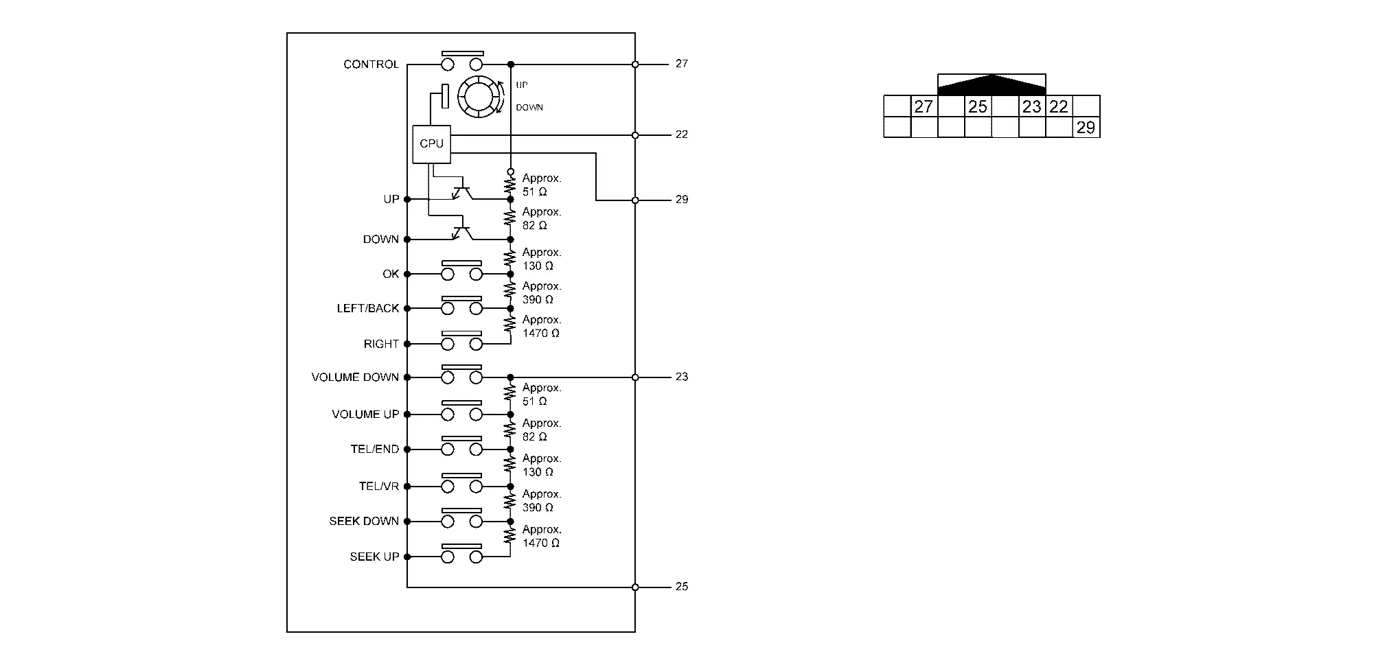
Is the inspection result normal?
YES>>Inspection End.
NO>>Replace steering switch. Refer to Removal and Installation.
Other materials:
P1c90-49 Sub Starter & Generator
DTC Description
DTC DETECTION LOGIC DTC No. CONSULT screen terms (Trouble diagnosis content) DTC detection condition
P1C90-49
Sub starter & generator
(Sub starter & generator)
Diagnosis condition
Engine running at idle
Signal (terminal)
-
Threshold
Sub starte ...
Electric Shift Control Module
Exploded View
Electric shift control module
: N·m (kg-m, in-lb) : Vehicle front
Removal and Installation
REMOVALDisconnect the negative battery terminal. Refer to Exploded View.
Remove instrument side panel LH. Refer to Exploded View.
Disconnect the harn ...
System Description. Component Parts. Drive Mode System
Drive Mode System
Component Parts Location
No. Component Function
1.
Drive mode select switch
Refer to Drive Mode Select Switch.
2.
Chassis control module
Chassis control module controls the drive mode select system.
Refer to Component Parts Location (without ProPILOT Assi ...