Nissan Rogue (T33) 2021-Present Service Manual: Type a :: Symptom Diagnosis
Head up Display Symptoms
Symptom Table
CAUTION:
If display distortion occurs after replacing the Head Up Display unit, perform calibration using CONSULT. Refer to CONSULT Function.
| Symptom | Reference |
|---|---|
| Head Up Display screen is not displayed. | Refer to Diagnosis Procedure. |
| Head Up Display brightness is not changed. | Refer to Diagnosis Procedure. |
| Head Up Display screen is not displayed in the correct position. | Refer to Diagnosis Procedure. |
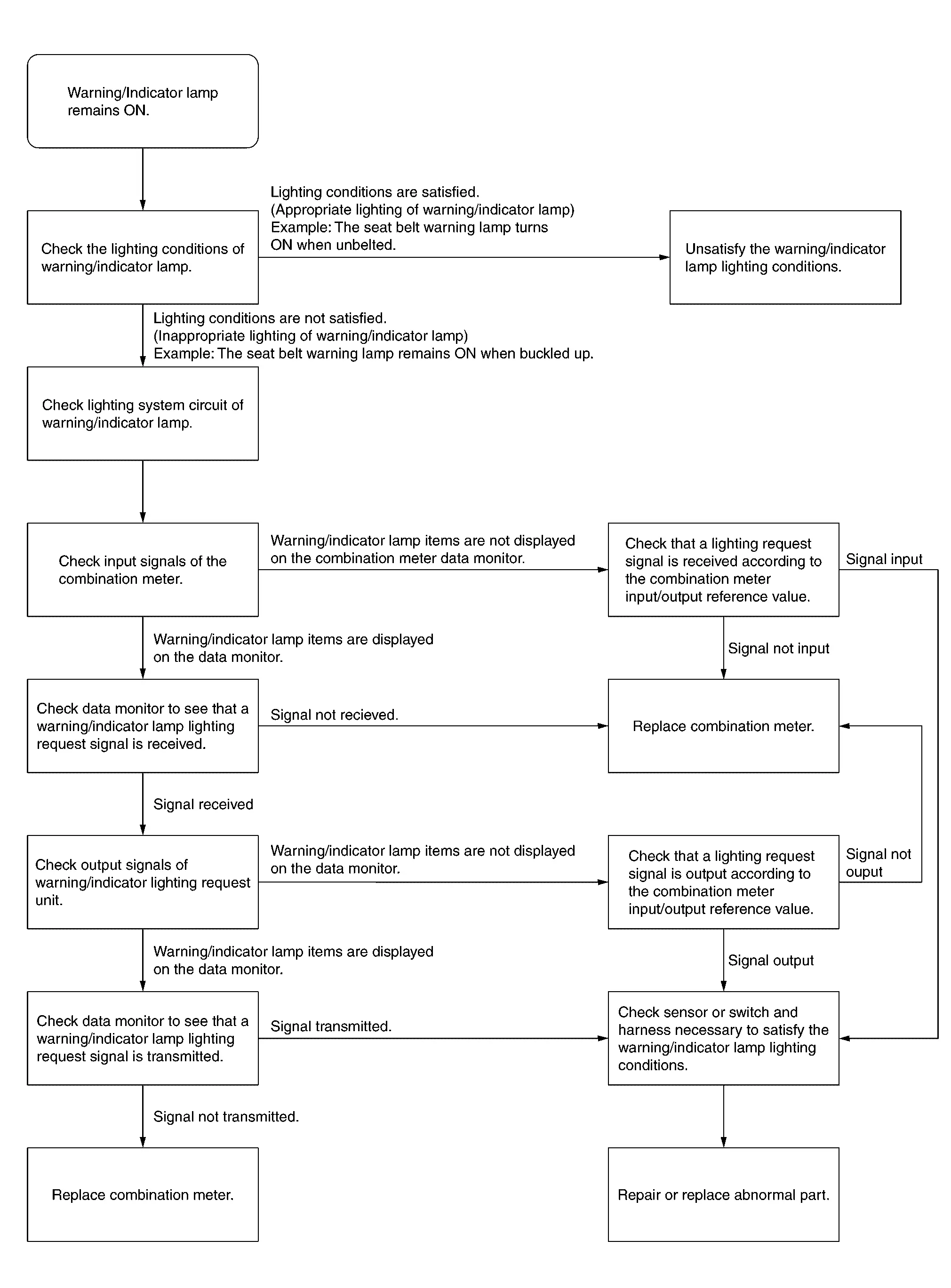
Warning/indicator Lamp Remains on
Work Flow
The Fuel Gauge Indicator Does Not Operate
Description
Fuel gauge will not indicate from a certain position.
Diagnosis Procedure
CONDUCTING THE COMBINATION METER SELF-DIAGNOSIS MODE
Perform the self-diagnosis mode of combination meter, and then check that the fuel gauge operates normally. Refer to On Board Diagnosis Function.
Is the inspection result normal?
YES>>GO TO 2.
NO>>Replace the combination meter. Refer to Removal and Installation.
CHECK FLOAT INTERFERENCE
Check that the float arm interferes with or binds to other components in the fuel tank.
Is the inspection result normal?
YES>>GO TO 3.
NO>>Repair or replace malfunctioning part.
CHECK FUEL LEVEL SENSOR SIGNAL CIRCUIT
Check the fuel level sensor signal circuit. Refer to Component Function Check.
Is the inspection result normal?
YES>>Refer to Intermittent Incident.
NO>>Repair or replace malfunctioning parts.
The Steering Switches Are Inoperative
Description
If any of the following malfunctions is found for the steering switch operation.
-
All switches are inoperative
-
The specified switch cannot be operated
Diagnosis Procedure
CHECK STEERING SWITCH SIGNAL A CIRCUIT
Check the steering switch signal A circuit. Refer to Component Function Check.
Is the inspection result normal?
YES>>GO TO 2.
NO>>Repair or replace malfunctioning parts.
CHECK STEERING SWITCH SIGNAL B CIRCUIT
Check the steering switch signal B circuit. Refer to Component Function Check.
Is the inspection result normal?
YES>>Replace combination meter. Refer to Removal and Installation.
NO>>Repair or replace malfunctioning parts.
The Illumination Control Switch Is Inoperative
Description
If any of the following malfunctions is found for the illumination control switch operation.
-
All switches are inoperative
-
The specified switch cannot be operated
Diagnosis Procedure
CHECK ILLUMINATION CONTROL SWITCH SIGNAL CIRCUIT
Check the illumination control switch signal circuit. Refer to Diagnosis Procedure.
Is the inspection result normal?
YES>>GO TO 2.
NO>>Repair harness or connector.
CHECK ILLUMINATION CONTROL SWITCH
Perform a unit check for the illumination control switch. Refer to Component Inspection.
Is the inspection result normal?
YES>>Replace combination meter. Refer to Removal and Installation.
NG>>Replace illumination control switch. Refer to Removal and Installation.
The Meter Speaker Does Not Sound
Description
The meter speaker does not sound.
Diagnosis Procedure
CHECK COMBINATION METER INPUT SIGNAL
 CONSULT
-
Select “Buzzer” in “Data monitor” mode of “M&A”.
-
Check that the function operates normally according to the following conditions:
Monitor item Condition Status Buzzer Under the condition of buzzer input ON Except above OFF
Is the inspection result normal?
YES>>GO TO 2.
NO>>Replace BCM. Refer to Removal and Installation.
CHECK METER SPEAKER CIRCUIT
Check meter speaker circuit. Refer to Diagnosis Procedure.
Is the inspection result normal?
YES>>Replace combination meter. Refer to Removal and Installation.
NO>>Repair or replace malfunctioning parts.
The Ambient Temperature Display Is Incorrect
Description
-
The displayed ambient air temperature is higher than the actual temperature.
-
The displayed ambient air temperature is lower than the actual temperature.
Diagnosis Procedure
 NOTE:
NOTE:
Check that the symptom is not applicable to the normal operating condition before starting diagnosis. Refer to Description.
CHECK AMBIENT SENSOR SIGNAL CIRCUIT
Check the ambient sensor signal circuit. Refer to Diagnosis Procedure.
Is the inspection result normal?
YES>>GO TO 2.
NO>>Repair or replace malfunctioning parts.
CHECK AMBIENT SENSOR
Check the ambient sensor. Refer to Component Inspection.
Is the inspection result normal?
YES>>Replace combination meter. Refer to Removal and Installation.
NO>>Replace ambient sensor. Refer to Removal and Installation.
Head up Display Screen Is Not Displayed
Diagnosis Procedure
CHECK HEAD UP DISPLAY SWITCH OPERATION
CONSULT
-
Ignition switch ON.
-
Select "Main switch" in "Data monitor" mode of "HEAD UP DISPLAY".
-
Check that the function operates normally according to the following conditions:
Monitor item Condition Indication Main switch Head Up Display switch Press the switch On Except above Off
Is the inspection result normal?
YES>>GO TO 2.
NO>>GO TO 3.
CHECK HEAD UP DISPLAY UNIT POWER SUPPLY CIRCUIT
Check the Head Up Display unit power supply circuit. Refer to Diagnosis Procedure.
Is the inspection result normal?
YES>>Replace Head Up Display unit. Refer to Removal and Installation.
NO>>Repair or replace malfunctioning parts.
CHECK HEAD UP DISPLAY SWITCH SIGNAL CIRCUIT
Check the head up display switch signal circuit. Refer to Diagnosis Procedure.
Is the inspection result normal?
YES>>GO TO 4.
NO>>Repair or replace harness or connector.
CHECK HEAD UP DISPLAY SWITCH
Check the Head Up Display switch. Refer to Component Inspection.
Is the inspection result normal?
YES>>Replace Head Up Display unit. Refer to Removal and Installation.
NO>>Replace Head Up Display switch. Refer to Removal and Installation.
Head up Display Brightness Is Not Changed
Diagnosis Procedure
CHECK HEAD UP DISPLAY BRIGHTNESS ADJUSTMENT SIGNAL
CONSULT
-
Select "Data Monitor" mode of "HEAD UP DISPLAY".
-
Check that the function operates normally according to the following conditions:
Monitor item Condition Indication Display brightness Press brightness adjustment on the combination meter setting screen. The display changes from (-10) to (10) Refer to Switch Name and Function.
Is the inspection result normal?
YES>>Replace Head Up Display unit. Refer to Removal and Installation.
NO>>Check Combination meter self diagnosis result. Refer to DTC Index.
Head up Display Screen Is Not Displayed in the Correct Position
Diagnosis Procedure
CHECK HEAD UP DISPLAY POSITION ADJUSTMENT SIGNAL
CONSULT
-
Select "Data Monitor" mode of "HEAD UP DISPLAY".
-
Check that the function operates normally according to the following conditions:
Monitor item Condition Indication Display up and down status Press each position adjustment on the combination meter setting screen. The display changes to (-10) - (10) Display rotation status The display changes to (-10) - (10)
Is the inspection result normal?
YES>>Replace Head Up Display unit. Refer to Removal and Installation.
NO>>Check Combination meter self diagnosis result. Refer to DTC Index.
Normal Operating Condition
Information Display
Description
DISTANCE TO EMPTY
The calculated distance to empty may differ from the actual distance to empty if the refueling amount is approximately 4  (7/8 Imp gal) or less. This is because the refuel control (moves the
fuel gauge needle quicker than normal judging that the driver is
refueling the Nissan Ariya vehicle) is not performing.
(7/8 Imp gal) or less. This is because the refuel control (moves the
fuel gauge needle quicker than normal judging that the driver is
refueling the Nissan Ariya vehicle) is not performing.
AMBIENT TEMPERATURE
The displayed ambient temperature on the information display may differ from the actual temperature because it is a corrected value calculated from the ambient sensor signal by the combination meter. Refer to System Description for details on the correction process.
Head up Display
Symptom Description
The Head Up Display unit controls and protects the backlight and display when the LED temperature becomes high. Refer to Protection Function.
Other materials:
B24a4-11 Intake Sensor
DTC Description
DTC DETECTION LOGIC DTC No.
CONSULT screen terms
(Trouble diagnosis content) DTC detection condition
B24A4-11
INTAKE SENSOR
(Intake sensor)
Diagnosis condition
Ignition switch ON
Signal (Terminal)
Intake sensor signal
Threshold
The intake sensor rec ...
Removal and Installation. Map Lamp
Exploded View
Headlining assembly
Map lamp assembly
Map lamp housing
Bulb
Lens
Map lamp finisher
: Pawl
: Metal clip
Removal and Installation
REMOVALCAUTION:
Disconnect the battery negative terminal or remove power
circuit fuse when performing t ...
P11b0 Vcr Target Angle (cold Start)
DTC Description
DTC DETECTION LOGIC DTC
CONSULT screen terms
(Trouble diagnosis content)
DTC detection condition
P11B0
00
VCR target angle (cold start)
[Variable compression ratio target angle (cold start)]
Diagnosis condition
Engine cold start
Signal (terminal)
â ...