Nissan Rogue (T33) 2021-Present Service Manual: Type a :: Removal and Installation
Combination Meter
Removal and Installation
CAUTION:
-
When replacing the combination meter, always replace it with a new one. The functions controlled by the combination meter does not operate properly in case of reuse of the combination meter from another Nissan Ariya vehicle.
-
Be sure to perform the configuration when replacing combination meter. Refer to Work Procedure.
REMOVAL
 NOTE:
NOTE:
Do not swap combination meter modules between Nissan Ariya vehicles for any reason.
Disconnect the battery cable from the negative terminal.
Remove cluster lid A. Refer to Removal and Installation.
Remove the mounting screws  of the combination meter
  .
.
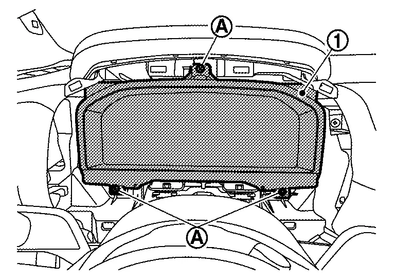
Pull the combination meter outward, then disconnect harness connectors and remove.
CAUTION:
Never damage the display.
INSTALLATION
Installation is in the reverse order of removal.
CAUTION:
-
Never damage the display.
-
When replacing the combination meter, always replace it with a new one. The functions controlled by the combination meter does not operate properly in case of reuse of the combination meter from another Nissan Ariya vehicle.
-
Be sure to perform the configuration when replacing combination meter. Refer to Work Procedure.
NOTE:
Do not swap combination meter modules between Nissan Ariya vehicles for any reason.
Meter Speaker
Removal and Installation
REMOVAL
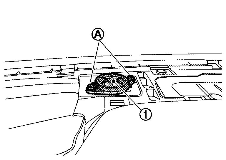
Remove instrument garnish. Refer to Removal and Installation.
Remove the meter speaker mounting screws, and remove the meter speaker .
INSTALLATION
Install in the reverse order of removal.
Steering Switches
Removal and Installation
REMOVAL
Refer to Removal and Installation.
NOTE:
Always remove steering switch together with steering wheel.
INSTALLATION
Installation is in the reverse order of removal.
Illumination Control Switch
Removal and Installation
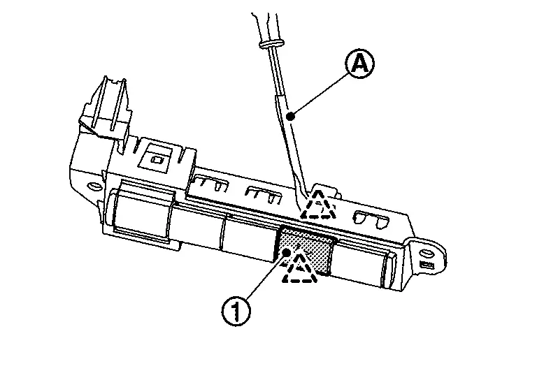
REMOVAL
Remove the instrument lower panel LH. Refer to Removal and Installation.
Remove screws to remove switch bracket .
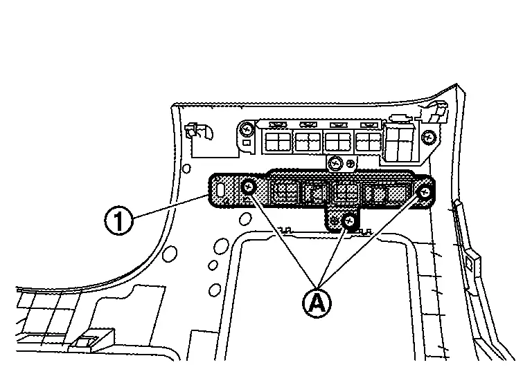
Disengage fixing pawl with removal tool to remove illumination control switch from switch bracket.
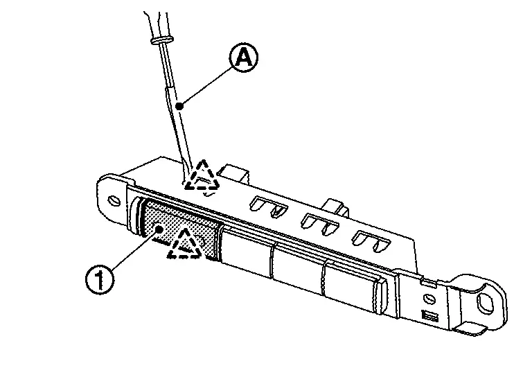
 |
ïžPawl |
INSTALLATION
Install in the reverse order of removal.
Ambient Sensor
Removal and Installation
REMOVAL
Disengage fixing pawl.
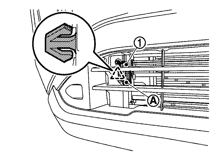
|
: Pawl |
Disconnect harness connector to remove ambient sensor .
INSTALLATION
Install in the reverse order of removal.
Oil Level Sensor
Removal and Installation
REMOVAL
Refer to Exploded View.
INSTALLATION
Install in the reverse order of removal.
Head up Display Unit
Exploded View
Exploded View
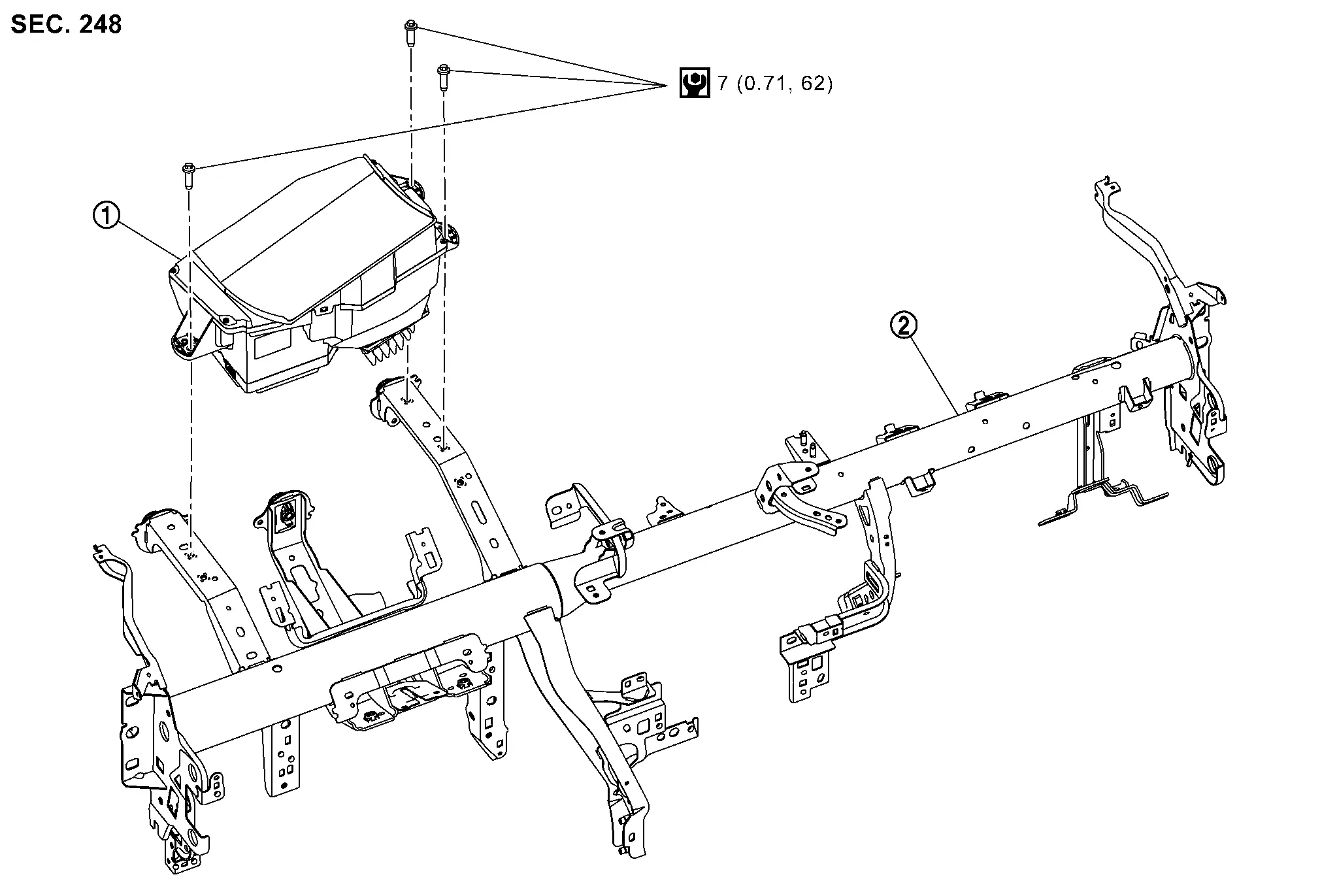
|
Head Up Display unit |  |
Steering member |
Removal and Installation
REMOVAL
-
Remove instrument panel assembly. Refer to Removal and Installation.
-
Remove Head Up Display unit mounting bolts
.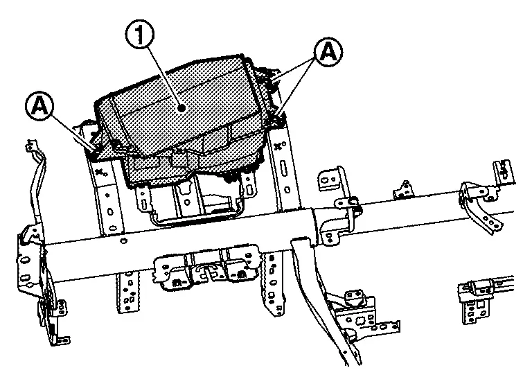
-
Disconnect the Head Up Display unit harness connector.
-
Remove Head Up Display unit
.
INSTALLATION
Installation is in the reverse order of removal.
CAUTION:
-
Never damage Head Up Display unit. if damaged for Head Up Display unit., replace it.
-
If replacing Head Up Display unit, be sure to remove protective sheet from the glass surface.
-
Be sure to perform âADDITIONAL SERVICE WHEN REPLACING HEAD UP DISPLAY UNITâ when replacing Head Up Display. For details, Refer to Work Procedure.
Head up Display Main Switch
Removal and Installation
REMOVAL
Remove the instrument lower panel LH. Refer to Removal and Installation.
Remove screws to remove switch bracket .
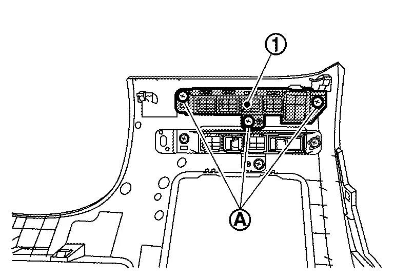
Disengage fixing pawl with removal tool to remove Head up Display main switch from switch bracket.
|
ïžPawl |
INSTALLATION
Installation is in the reverse order of removal.
Other materials:
Symptom Diagnosis. Ignition Position Warning Function Does Not Operate
Diagnosis Procedure
CHECK POWER DOOR LOCK OPERATION
Check door lock/unlock using door lock/unlock switch.
Does door lock/unlock with door lock/unlock switch?
YES>>
GO TO 2.
NO>>
Refer to Diagnosis Procedure.
CHECK DOOR SWITCH
Check front door switch (front LH).
Refer to Compo ...
Espaces de rangement et commoditÃĐs du Nissan Rogue. Porte-gobelets ergonomiques
Porte-gobelets ergonomiques
Informations et sÃĐcuritÃĐ
MISE EN GARDE
Pour ÃĐviter tout risque de brÃŧlure ou de projection de liquide dans l'habitacle du Nissan Rogue, adoptez une conduite souple et ÃĐvitez les manÅuvres brusques lorsque des boissons sont prÃĐsentes dans les supports.
...
Dtc/circuit Diagnosis. Front Washer Circuit
Component Function Check
CHECK FRONT WASHER OPERATION
When the front washer switch is turned to the ON position the front washer should operate.
Is front washer operation normal?
YES>>
Washer switch circuit is normal.
NO>>
Refer to Diagnosis Procedure.
Diagnosis Procedure
COMB ...