Nissan Rogue (T33) 2021-Present Service Manual: Transfer: Ty92a :: System Description
Component Parts
Kr15ddt
Component Parts Location
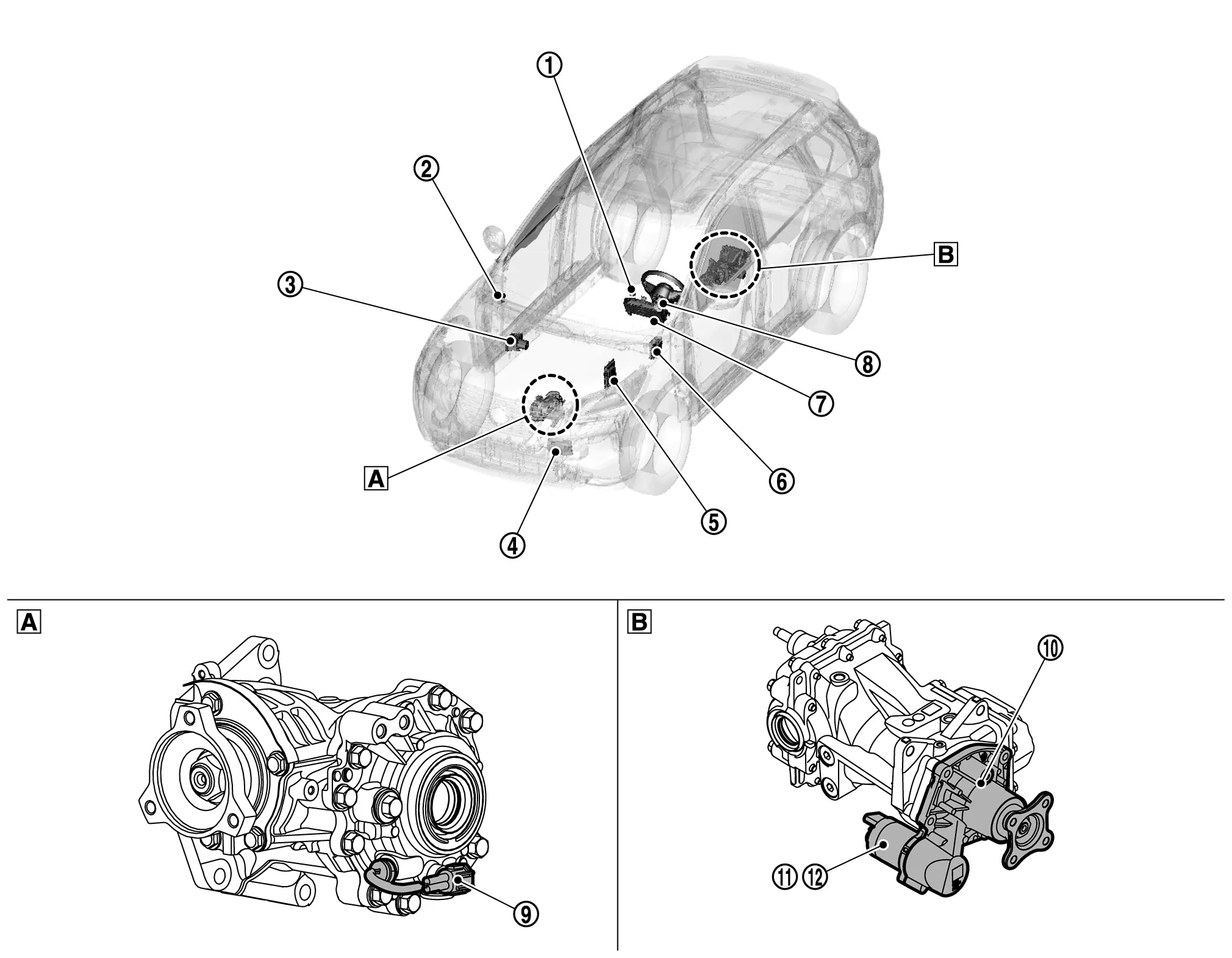
| A. | Transfer case assembly | B. | Rear final drive assembly |
| No. | Component | Function |
|---|---|---|
| 1. | Drive mode switch | Refer to Component Parts Location for detailed component location. |
| 2. | Chassis control module |
Chassis control module transmits the drive mode signal to ADAS control unit 2 via CAN communication. Refer to Component Parts Location for detailed component location. |
| 3. |
ABS actuator and electric unit (control unit) [Anti-lock Braking System actuator and electric unit (control unit)] |
Transmits/receives the signals for control of AWD system via CAN communication line to/from AWD control unit. Refer to Component Parts Location for detailed component location. |
| 4. |
TCM (Transmission Control Module) |
Transmits/receives the signals for control of AWD system via CAN communication line to/from AWD control unit. Refer to Component Parts Location for detailed component location. |
| 5. |
ECM (Engine Control Module) |
Transmits/receives the signals for control of AWD system via CAN communication line to/from AWD control unit. Refer to Component Parts Location for detailed component location. |
| 6. | BCM (Body Control Module) | Refer to Component Parts Location for detailed component location. |
| 7. |
Combination meter [AWD (all wheel drive) warning icon/display] |
Transmits/receives the signals for control of AWD system via CAN communication line to/from AWD control unit. Refer to Combination Meter (type A meter) or Combination Meter (type B meter) for detailed component location. |
| 8. | Steering angle sensor |
Transmits/receives the signals for control of AWD system via CAN communication line to/from AWD control unit. Refer to Component Parts Location for detailed component location. |
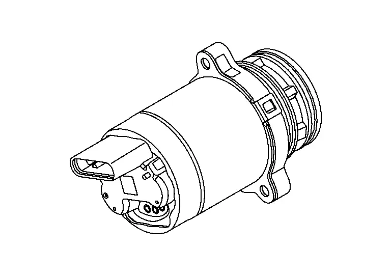
| 9. | Transfer oil temperature sensor |
Transmits transfer oil temperature to the AWD control unit. Refer to Transfer Oil Temperature Sensor. |
| 10. | Electro-hydraulic coupling | Refer to Electro-hydraulic Coupling. |
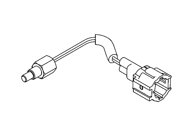
| 11. |
AWD control unit (Integrated with actuator assembly) |
Refer to AWD Control Unit. |
| 12. | Actuator assembly | Integrated into the AWD control unit and engages rear differential. Refer to Refer to AWD Control Unit. |
AWD Control Unit
-
Controls driving force distribution by signals from each sensor from front wheel driving mode (100:0) to 4-wheel driving mode (50:50).
-
Fail-safe mode is available if malfunction is detected in AWD system. For fail-safe, refer to Fail-Safe.
-
AWD control unit is integrated with actuator assembly of electro-hydraulic coupling assembly. For installation location of actuator assembly, refer to Component Parts Location.
Electro-hydraulic Coupling
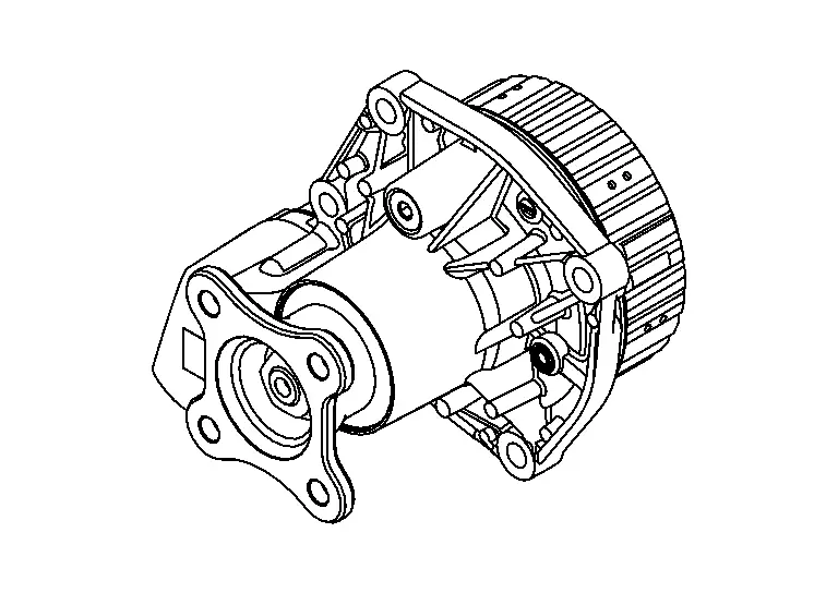
-
Electro-hydraulic coupling is installed on front of rear final drive and transmits driving force to rear final drive.
-
Electro-hydraulic coupling assembly include actuator assembly.
-
For operation, refer to Operation Description.
-
For detailed installation location, refer to Component Parts Location.
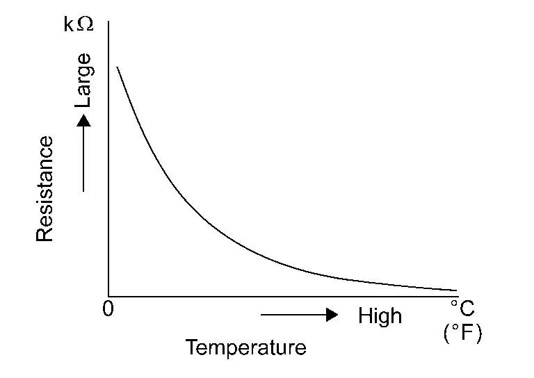
Transfer Oil Temperature Sensor
-
Transfer oil temperature sensor detects the transfer oil temperature and transmits a signal to AWD control unit.
-
The electrical resistance of the sensor decreases as temperature increases.
-
Transfer oil temperature sensor is installed on transfer case. For detailed installation location, refer to Component Parts Location.
Structure and Operation
Sectional View
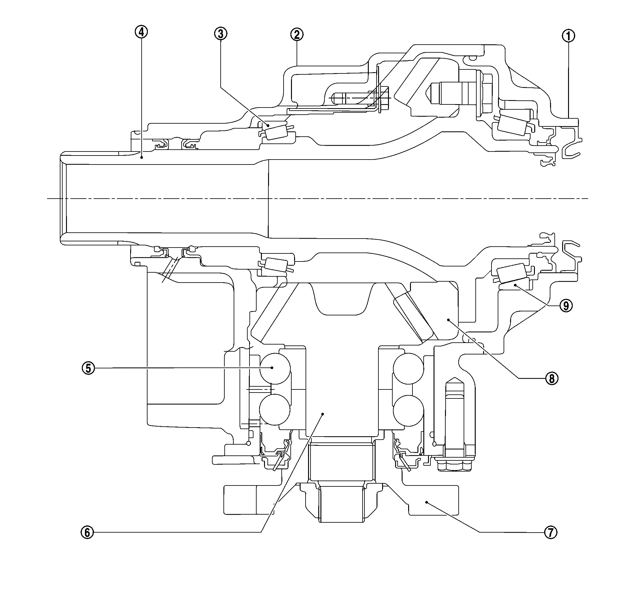
| 1. | Transfer cover | 2. | Transfer case | 3. | Ring gear bearing (transfer case side) |
| 4. | Ring gear shaft | 5. | Pinion bearing | 6. | Drive pinion |
| 7. | Companion flange | 8. | Ring gear | 9. | Ring gear bearing (transfer cover side) |
Operation Description
POWER TRANSFER DIAGRAM
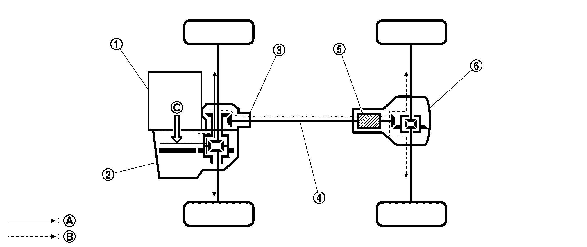
| 1. | Engine | 2. | Transaxle | 3. | Transfer |
| 4. | Propeller shaft | 5. | Electro-hydraulic coupling | 6. | Rear final drive |
| A. | Power transmission to front wheels | B. | Power transmission to rear wheels | C. | Power from engine |
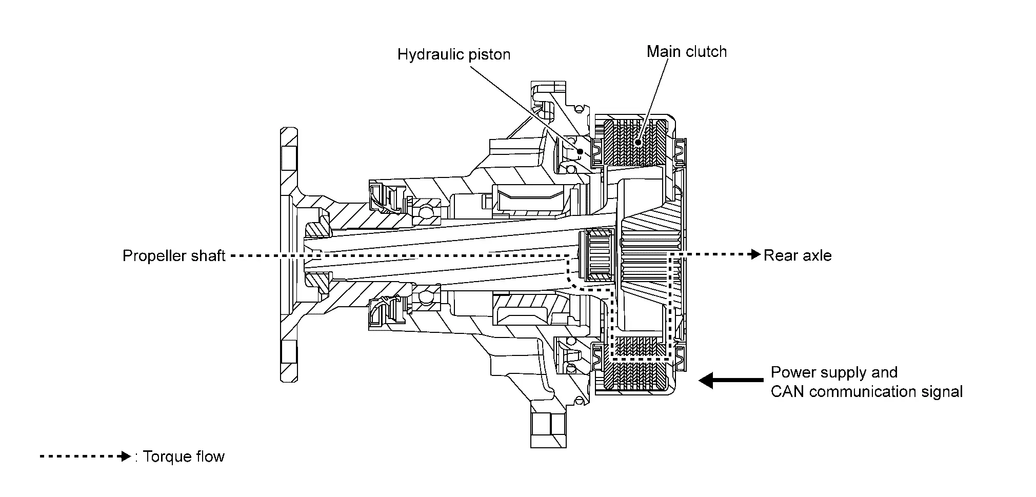
ELECTRO-HYDRAULIC COUPLING
-
AWD control unit (Integrated with actuator assembly) receives the CAN communication signal from the Nissan Ariya vehicle and judges the vehicle condition.
-
The actuator operates according to the command from the AWD control unit, and the hydraulic piston generates hydraulic pressure according to the Nissan Ariya vehicle condition.
-
The main clutch is pressed by the hydraulic pressure generated by the hydraulic piston, and clutch plates (inner side and outer side) are engaged
-
The main clutch transmits torque to rear wheels according to the hydraulic pressure from actuator.
System
Awd System
System Description
-
According to signal information from each sensor and switch, the driving torque distribution of front and rear wheels is judged, and pressing force of multiple disc clutch is controlled by electric control.
-
Driving torque distribution of front and rear wheels changes automatically between approximately 100 : 0 (2WD) and 50 : 50 (AWD) to have an optimized torque distribution adapted to road condition change.
-
The optimal driving torque is distributed according to the driving mode selected by the drive mode selector. Refer to System Description (AWD Models).
-
Fail-safe function is activated if malfunction is detected in AWD system. Refer to Fail-Safe.
-
When a high load status continues for electro-hydraulic coupling, AWD control temporarily becomes front wheel drive, according to protection function. Refer to Protection Function.
SYSTEM DIAGRAM
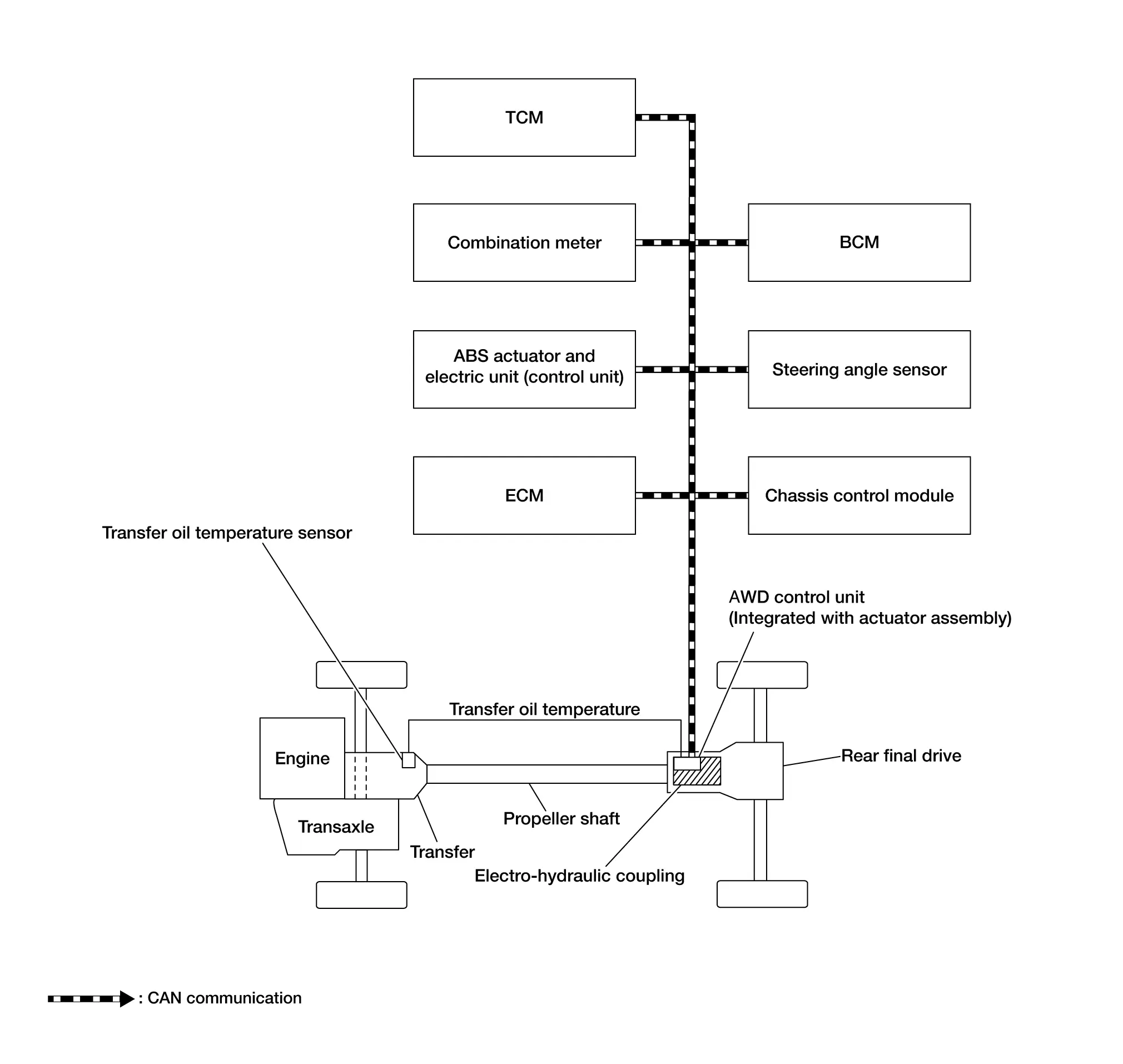
INPUT SIGNAL AND OUTPUT SIGNAL
Major signal transmission between each unit via CAN communication lines are shown in the following table.
| Component parts | Function |
|---|---|
|
AWD control unit (Integrated with actuator assembly) |
Refer to AWD Control Unit. |
| Electro-hydraulic coupling | Refer to Electro-hydraulic Coupling. |
| Transfer oil temperature sensor | Refer to Transfer Oil Temperature Sensor. |
| ECM |
Mainly transmits the following signals to AWD control unit via CAN communication.
|
| ABS actuator and electric unit (control unit) |
Mainly transmits the following signals to AWD control unit via CAN communication.
|
| Combination meter |
Mainly transmits the following signals to AWD control unit via CAN communication.
Mainly receives the following signals from AWD control unit via CAN communication.
|
| TCM |
Mainly transmits the following signals to AWD control unit via CAN communication.
|
| BCM |
Mainly transmits the following signal to AWD control unit via CAN communication.
|
| Steering angle sensor |
Mainly transmits the following signal to AWD control unit via CAN communication.
|
| Chassis control module |
Mainly transmits the following signal to AWD control unit via CAN communication.
|
Control in Each Mode
For driving modes other than AUTO mode by drive mode selector, refer to System Description (AWD Models).
AUTO MODE
-
Electronic control allows optimal distribution of torque to front/rear wheels to match road conditions.
-
Pressing force of multiple disc clutch is controlled by electric control. Driving torque distribution of front and rear wheels changes automatically between approximately 100 : 0 (2WD) and 50 : 50 (AWD) to have an optimized torque distribution adapted to road condition change.
-
Sensor inputs determine the Nissan Ariya vehicle's turning condition, and tight cornering/braking are controlled by distributing optimum torque to rear wheels.
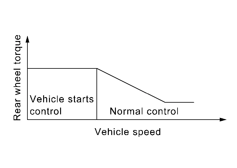
Vehicle Starts Control
-
At the start, torque distribution for front and rear wheels is fixed by electric control and stable start is achieved.
-
Makes possible stable driving, with no wheel spin, on snowy roads or other slippery surfaces.
Normal Control
-
On roads which do not require AWD, it contributes to improved fuel economy by driving in conditions close to front-wheel drive and it results in better fuel efficiency.
-
When spin occurs on front wheel, distribute optimum torque to rear wheel and keep stable driving.
-
The Nissan Ariya vehicle cornering status is judged according to information from each sensor, and the optimum torque is distributed to rear wheels for preventing tight cornering/braking symptom.
Information Display (combination Meter)
AWD Warning
DESIGN/PURPOSE
AWD warning is displayed when the AWD system has a malfunction. AWD warning indicates that the vehicle is in fail-safe mode or protection function mode.
| Symbol | Message | Condition |
|---|---|---|
|
|
AWD Error See Owner’s Manual |
AWD system malfunction. |
|
AWD High Temp. Stop Nissan Ariya vehicle |
Protection function is activated due to heavy load to electro-hydraulic coupling. (AWD system is not malfunctioning and AWD system changes to front wheel drive.) | |
|
Tire Size Incorrect See Owner’s Manual |
Large difference in diameter of front/rear tires. |

SYNCHRONIZATION WITH MASTER WARNING LAMP
Applicable
For master warning lamp, refer to Master Warning Lamp (type A meter), Master Warning Lamp (type B meter).
SYSTEM DIAGRAM
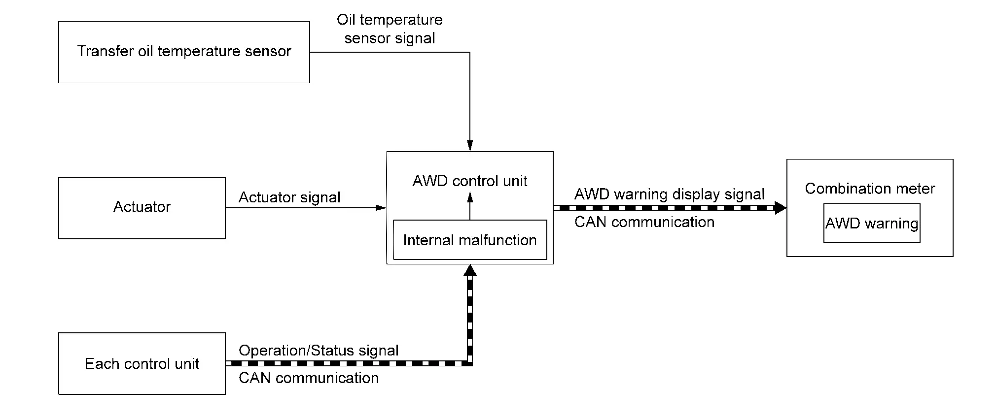
SIGNAL PATH
-
The AWD control unit judges and decides a mode from among normal mode, fail-safe mode, and protection function mode, according to signals received from each sensor, and control unit.
-
The AWD control unit transmits AWD warning display signal to the combination meter via CAN communication when judging fail-safe mode or protection function mode.
-
The combination meter displays AWD warning on the information display when receiving AWD warning display signal transmitted from the AWD control unit.
WARNING CONDITION
AWD warning is displayed when the AWD system goes into fail-safe mode or protection function mode.
WARNING CANCEL CONDITION
When any of the conditions listed below is satisfied:
-
Ignition switch is in a position other than ON.
-
AWD warning becomes invisible when the AWD system returns to normal.
AWD Torque Distribution Indicator
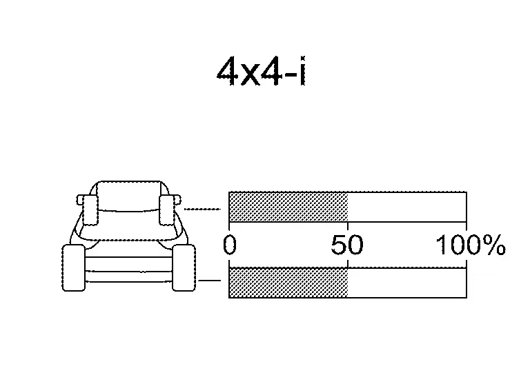
DESIGN/PURPOSE
| Design | Purpose |
|---|---|
|
|
Displays the drive torque distribution to the front and rear wheels while driving and informs the driver of this.
The driving force distribution may not match actual one. This is not a system malfunction. |
Warning/indicator/chime List
Warning/Indicator (On Information Display)
| Name | Function |
|---|---|
| AWD warning | Refer to AWD Warning. |
| AWD torque distribution indicator | Refer to AWD Torque Distribution Indicator. |
Diagnosis System (awd Control Unit)
CONSULT Function
APPLICATION ITEMS
CONSULT can display each diagnostic item using the diagnostic test modes as follows.
| Diagnosis mode | Function |
|---|---|
| Self diagnosis result | Display non-network DTC which AWD control unit memorizes* |
| ECU identification | The AWD control unit part number is displayed |
| Work supports | Changes the setting for each system function |
| Data monitor | The AWD control unit input/output signals are displayed |
| Replace ECU | Writes the Nissan Ariya vehicle specification when replacing the AWD control unit. |
| ECU Reprogramming | Allows reprogramming when replacing the AWD control unit. |
*: The following diagnosis information is erased by erasing:
-
DTC
-
Freeze frame data (FFD)
Self diagnosis result
Refer to DTC Index.
When “Current” is displayed on "Self diagnosis result".
-
The system is presently malfunctioning.
When “Past” is displayed on "Self diagnosis result".
-
System malfunction in the past is detected, but the system is presently normal.
Freeze Frame Data (FFD)
The following vehicle status is recorded when DTC is detected and is displayed:
| Freeze Frame Data Item | Description |
|---|---|
| IGN COUNTER [0 - 39] |
The number of times that ignition switch is placed ON after the DTC is detected is displayed.
|
ECU identification
AWD control unit part number can be read.
Work support
| Item | Usage |
|---|---|
| BLEED AIR & INITIALIZE OIL DETERIORATION LEVEL | Air bleeding in oil passage and initialize oil deterioration level of electro-hydraulic coupling oil of AWD control unit. |
Data monitor
 NOTE:
NOTE:
The following table includes information (items) inapplicable to this Nissan Ariya vehicle: For information (items) applicable to this vehicle, refer to CONSULT display items.
| Monitor item (Unit) | Remarks | ||
|---|---|---|---|
| Warning lamp (On/Off) | Control status of AWD warning (on information display) is displayed. | ||
| Different diameter tire monitor (mm) | Improper size tire installed condition is displayed. | ||
| Rear RH wheel speed (mph or km/h) | Wheel speed calculated by rear RH wheel sensor signal is displayed. | ||
| Rear LH wheel speed (mph or km/h) | Wheel speed calculated by rear LH wheel sensor signal is displayed. | ||
Replace ECU
Writes the vehicle specification when replacing the AWD control unit.
ECU Reprogramming
Allows reprogramming when replacing the AWD control unit.
Other materials:
P0335 Ckp Sensor 1
DTC Description
DTC DETECTION LOGIC DTC
CONSULT screen terms
(Trouble diagnosis content)
DTC detection condition
P0335
00
CKP SEN/CIRCUIT
(Crankshaft position sensor “A” circuit)
Diagnosis condition
Engine running or cranking
Signal (terminal)
Crankshaft posit ...
Wireless Charger. System Description
Component Parts
Wireless Charger
Component Parts Location
A.
Console finisher assembly
No.Component
1.
Wireless charger unit
2.
Wireless charger indicator
Wireless charger unit
Wireless charger unit
The wireless unit is located at the front of the center console.
Wirel ...
Multi Remote Ent
CONSULT Function (BCM - MULTI REMOTE ENT)
DATA MONITORNOTE:
The following table includes information (items)
inapplicable to this Nissan Ariya vehicle. For information (items)
applicable to this vehicle, refer to CONSULT display items.
Monitor Item Condition
Stop/start switch
[On/Off] ...