Nissan Rogue (T33) 2021-Present Service Manual: Timing Chain
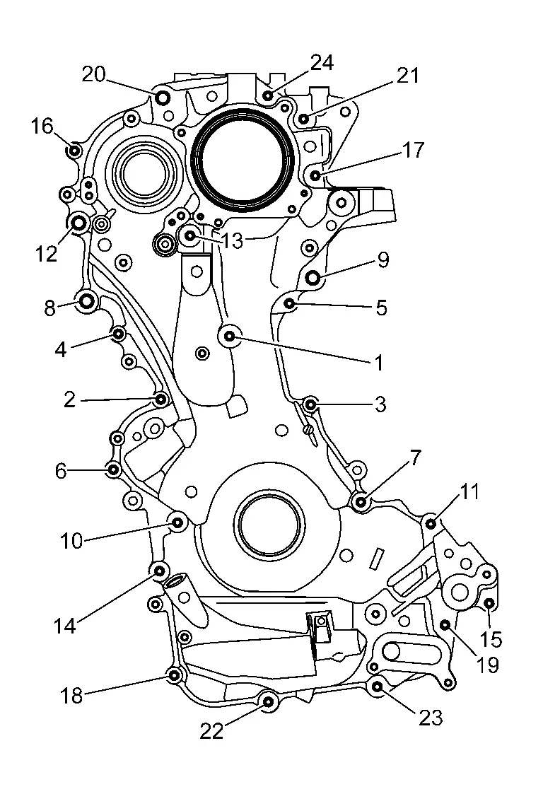
Exploded View
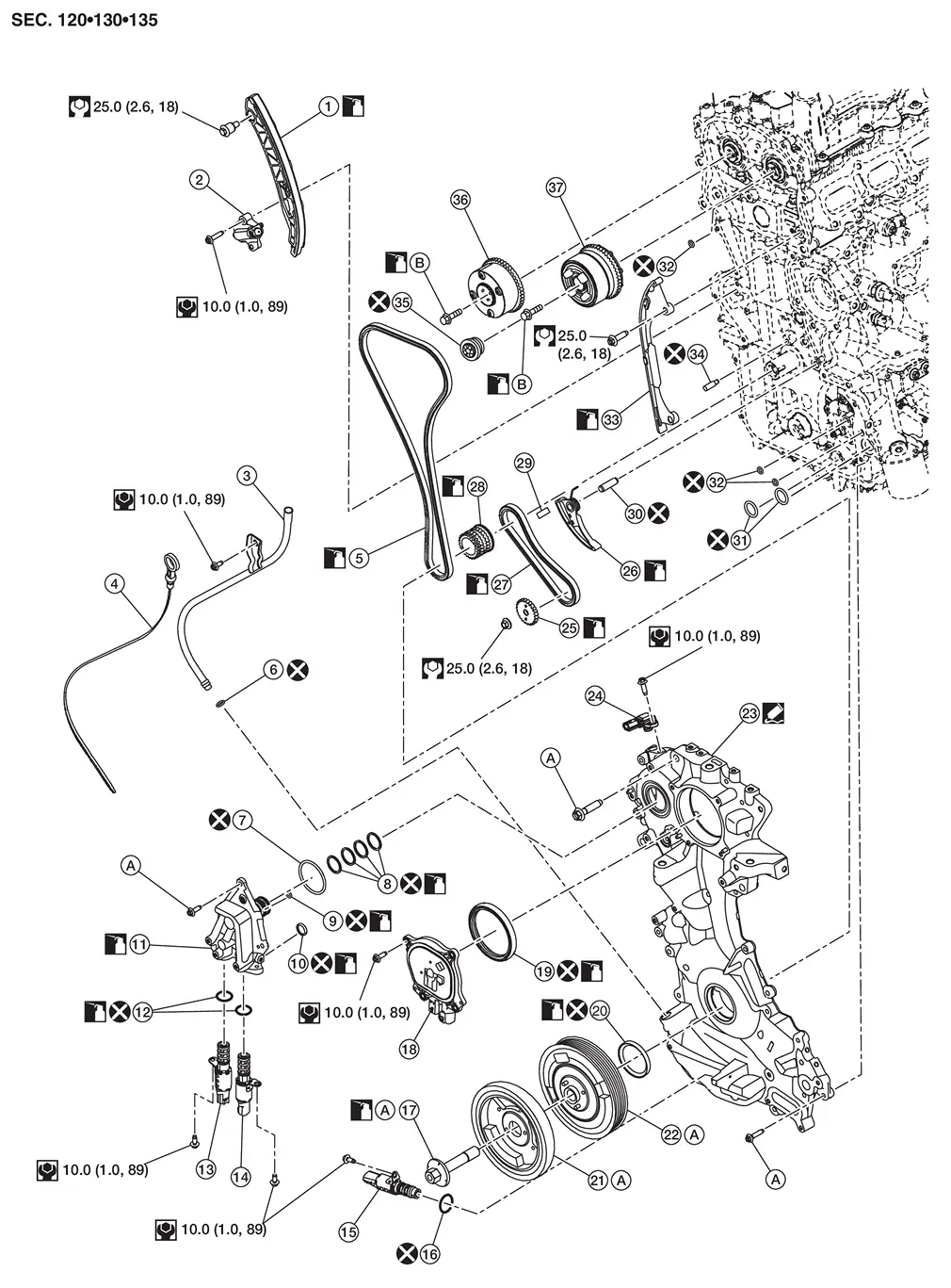
| 1. | Slack guide | 2. | Timing chain tensioner | 3. | Oil level gauge guide |
| 4. | Oil level gauge | 5. | Timing chain | 6. | O-ring |
| 7. | O-ring | 8. | O-ring | 9. | O-ring |
| 10. | Oil filter | 11. | Valve timing control cover | 12. | O-ring |
| 13. | Exhaust valve timing control solenoid valve | 14. | Exhaust valve timing intermediate lock control solenoid valve | 15. | Engine oil pressure control solenoid valve |
| 16. | O-ring | 17. | Crankshaft pulley bolt | 18. | Electric intake valve timing control actuator |
| 19. | Camshaft sprocket (INT) oil seal | 20. | Front oil seal | 21. | Crankshaft pulley damper |
| 22. | Crankshaft pulley | 23. | Front cover | 24. | Crankcase Pressure Sensor |
| 25. | Oil pump sprocket | 26. | Oil pump drive chain tensioner | 27. | Oil pump drive chain |
| 28. | Crankshaft sprocket | 29. | Crankshaft key | 30. | Tensioner arm shaft |
| 31. | O-ring | 32. | O-ring | 33. | Tension guide |
| 34. | Timing chain oil jet | 35. | Electric intake valve timing control actuator target | 36. | Camshaft sprocket (EXH) |
| 37. | Camshaft sprocket (INT) | A | Comply with the assembly procedure when tightening. Refer to Removal and Installation. | B | Comply with the assembly procedure when tightening. Refer to Removal and Installation. |
Removal and Installation
TIMING CHAIN
REMOVAL
 NOTE:
NOTE:
When removing the timing chain, remove the engine assembly from the Nissan Ariya vehicle.
Remove drive belt and then remove drive belt auto-tensioner. Refer to Removal and Installation.
Disconnect exhaust valve timing control valve harness connectors.
Remove exhaust valve timing control valve.
Loosen valve timing control cover bolts in reverse of the sequence shown and remove valve timing control cover.
Disconnect electric valve timing control actuator harness connectors.
Loosen electric valve timing control actuator bolts and remove electric valve timing control actuator.
Disconnect engine oil pressure control solenoid valve harness connector.
Loosen engine oil pressure control solenoid valve bolt and remove engine oil pressure control solenoid valve.
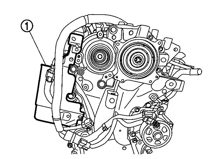
Remove the harness bracket (1).
Remove the oil cooler. Refer toRemoval and Installation.
Remove the engine oil level gauge guide
Remove the sub starter & generator and compressor bracket. Refer to Removal and Installation.
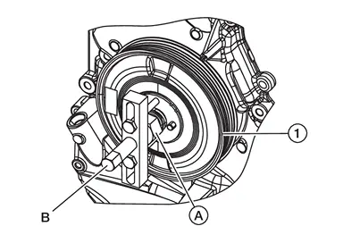
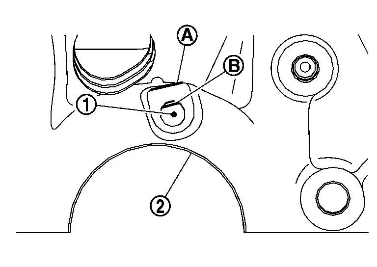
Set No. 1 cylinder at TDC on its exhaust stroke using the following procedure:Remove the rocker cover. Refer to Removal and Installation. Rotate the crankshaft pulley (1) clockwise to align timing mark [grooved line without color (B) ] with timing indicator (A).
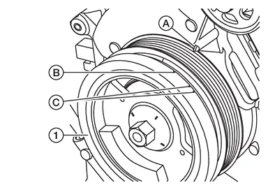
| C. |
: White paint mark (Not use for service) |
| 1. | : Camshaft (EXH) |
| 2. | : Camshaft (INT) |
 |
: Cylinder head side |
Remove crankshaft pulley using the following procedure:Loosen crankshaft pulley bolt.
CAUTION:
Do not remove the crankshaft pulley bolt as it is used as a supporting point for a suitable puller.
NOTE:
There should be approximately a 5 mm (0,20 in) gap between the flange on crankshaft pulley bolt and crankshaft pulley damper.
Attach a suitable puller (A) to the threaded holes on the crankshaft pulley damper (1) and remove crankshaft pulley damper.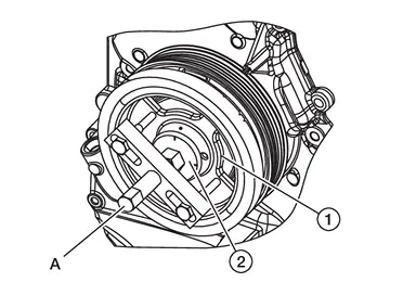
CAUTION:
-
Do not use a claw or hook style puller because damage to crankshaft pulley damper may occur.
-
Do not allow the bolts for the suitable puller to thread through crankshaft pulley damper and contact crankshaft pulley because damage to crankshaft pulley may occur.
| (2) | : Crankshaft pulley bolt |
CAUTION:
Do not use a claw or hook style puller because damage to crankshaft pulley damper may occur.
| Thread | Length | |
| Bolt | M16x1.5 | 100 mm (1.38 in) |
Remove front cover using the following procedure:Loosen front cover bolts in reverse of the sequence shown.
CAUTION:
Do not damage the front cover.
Remove the front cover.
CAUTION:
Do not reuse O-ring.
Remove front oil seal using suitable tool.
CAUTION:
-
Do not damage the front cover.
-
Do not reuse front oil seal.
Remove camshaft sprocket (INT) oil seal using suitable tool.
CAUTION:
-
Do not damage the front cover.
-
Do not reuse camshaft sprocket (INT) oil seal.
Remove timing chain tensioner using the following procedure:Push in timing chain tensioner plunger. Insert a suitable tool (A) into the body hole, and then secure it with the plunger pushed in.
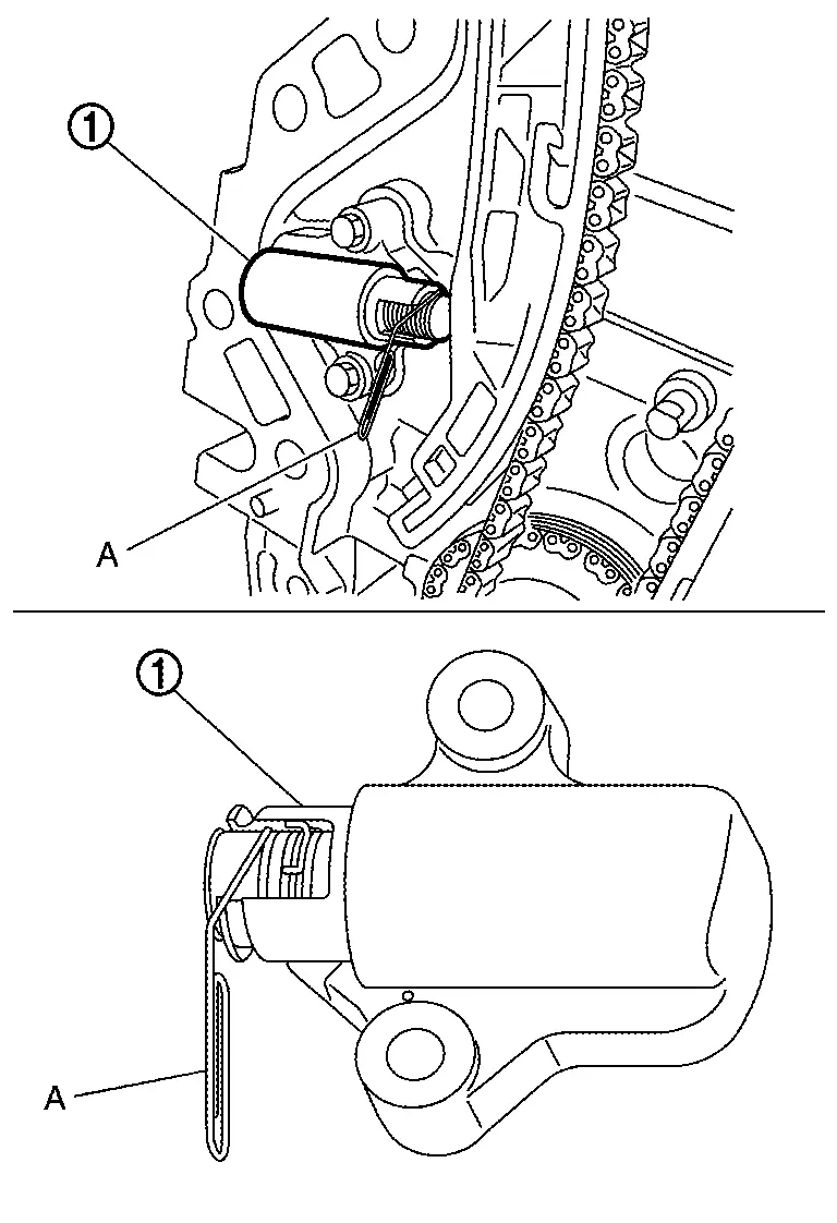
| 1. | : Timing chain tensioner |
CAUTION:
Do not remove suitable tool (A) from timing chain tensioner when removed from Nissan Ariya vehicle. If timing chain tensioner plunger becomes fully extended, replace timing chain tensioner.
Remove slack guide (2), timing chain tension guide (3) and timing chain (1).
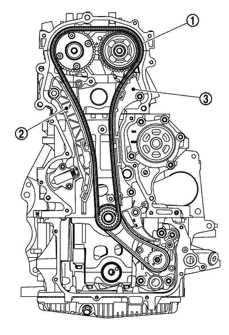
CAUTION:
Do not rotate the crankshaft and camshafts individually while timing chain is removed. It causes interference between valve and piston.
Release oil pump drive chain tensioner spring from hole (A) in cylinder block and remove oil pump drive chain tensioner (1).
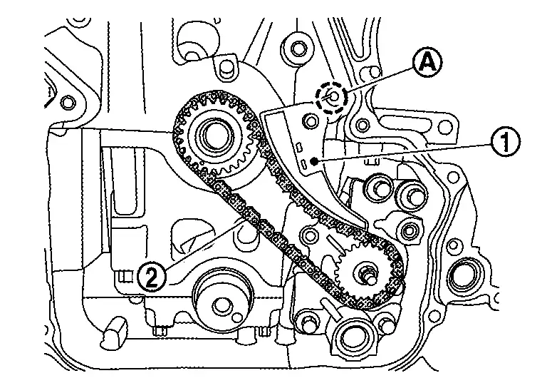
| 2. | : Oil pump drive chain |
Use a torx socket to hold the end of the oil pump shaft (1) and loosen the oil pump sprocket mounting nut (A).
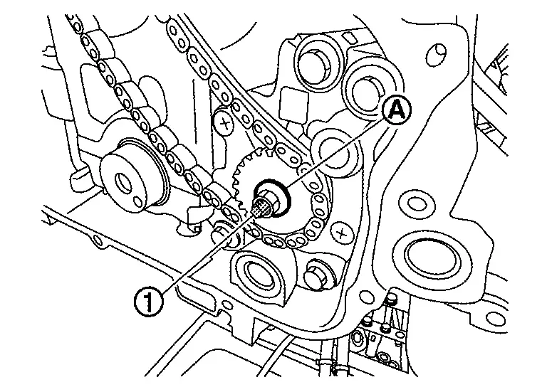
Remove the crank sprocket, oil pump drive chain, and oil pump sprocket, at the same time.
INSTALLATION
CAUTION:
-
Do not reuse oil pump drive chain tensioner shaft or timing chain oil jet.
-
Do not reuse O-rings.
NOTE:
The illustration shows the relationship between the matching mark on each timing chain and that on the corresponding sprocket, with the components installed.
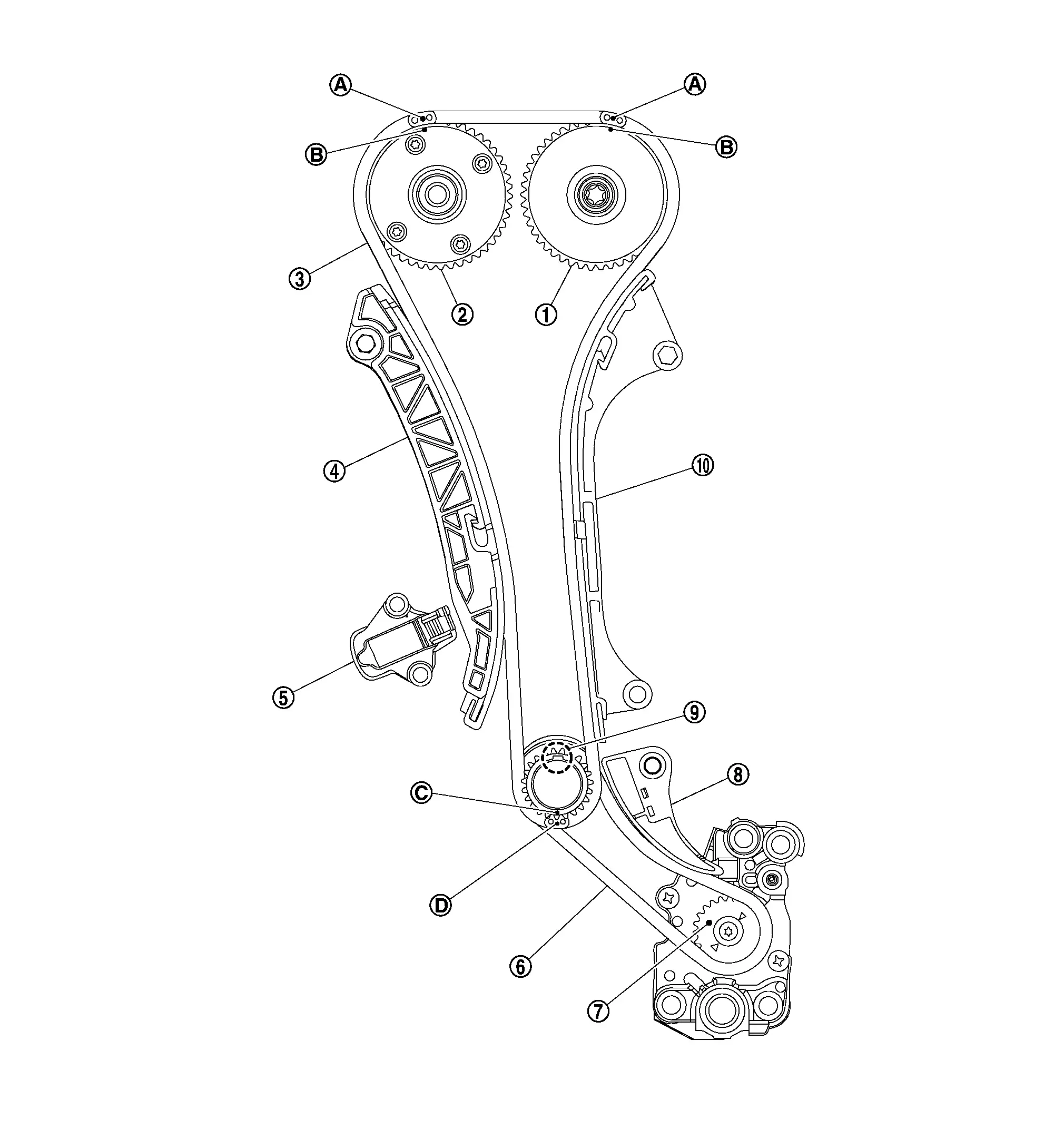
| 1. | Camshaft sprocket (INT) | 2. | Camshaft sprocket (EXH) | 3. | Timing chain |
| 4. | Slack guide | 5. | Timing chain tensioner | 6. | Oil pump drive chain |
| 7. | Oil pump drive sprocket | 8. | Oil pump drive chain tensioner | 9. | Crankshaft key |
| 10. | Tension guide | — | — | — | — |
| A. | Mating mark (blue link) | B. | Mating mark | C. | Mating mark |
| D. | Mating mark (yellow link) | — | — | — | — |
If removed, install the oil pump drive chain tensioner shaft (1) to specified height (A).
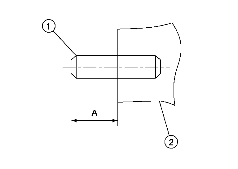
| Height (A) | : 17.6 – 18.3 mm (0.0693 – 0.720 in) |
| 2. | : Engine block |
Install the timing chain oil jet (1) so that the section of cylinder block side (A) and the section of timing chain oil jet side (B) become parallel with each other.
| 2. | : Engine block |
Install the oil pump drive chain, crankshaft sprocket and oil pump drive chain sprocket onto the engine as an assembly.
Using a suitable tool, secure the oil pump shaft (1) and tighten the oil pump nut (A).
Install the oil pump drive chain tensioner (1) onto the oil pump drive chain tensioner shaft and insert the spring from hole (A) in cylinder block.
| 2. | : Oil pump drive chain |
Align the matching marks of each sprocket with the matching marks of timing chain.
-
If these matching marks are not aligned, rotate the camshaft slightly by holding the hexagonal portion to correct the position.
CAUTION:
Check matching mark position of each sprocket and timing chain again after installing the timing chain.
Install the timing chain tension guide (3) and the slack guide (2).
| 1. | : Timing chain |
Install the timing chain tensioner (1).
-
Securely pull out the suitable tool (A) after installing the timing chain tensioner.
CAUTION:
Do not remove suitable tool (A) from timing chain tensioner when removed from Nissan Ariya vehicle. If timing chain tensioner plunger becomes fully extended, replace timing chain tensioner.
Check matching mark position of timing chain and each sprocket again.
Install front oil seal. Refer to Removal and Installation.
Install camshaft sprocket (INT) oil seal using suitable tool.
Install front cover with the following procedure:Apply RTV Silicone Sealant (equivalent product) to the positions shown in the figure between the cylinder block and upper/lower bonded parts, making sure that there are no breaks or overlaps. Refer to Precautions For Engine Service.
-
Use Genuine RTV Silicone Sealant or an equivalent. Refer to Recommended Chemical Products and Sealants.
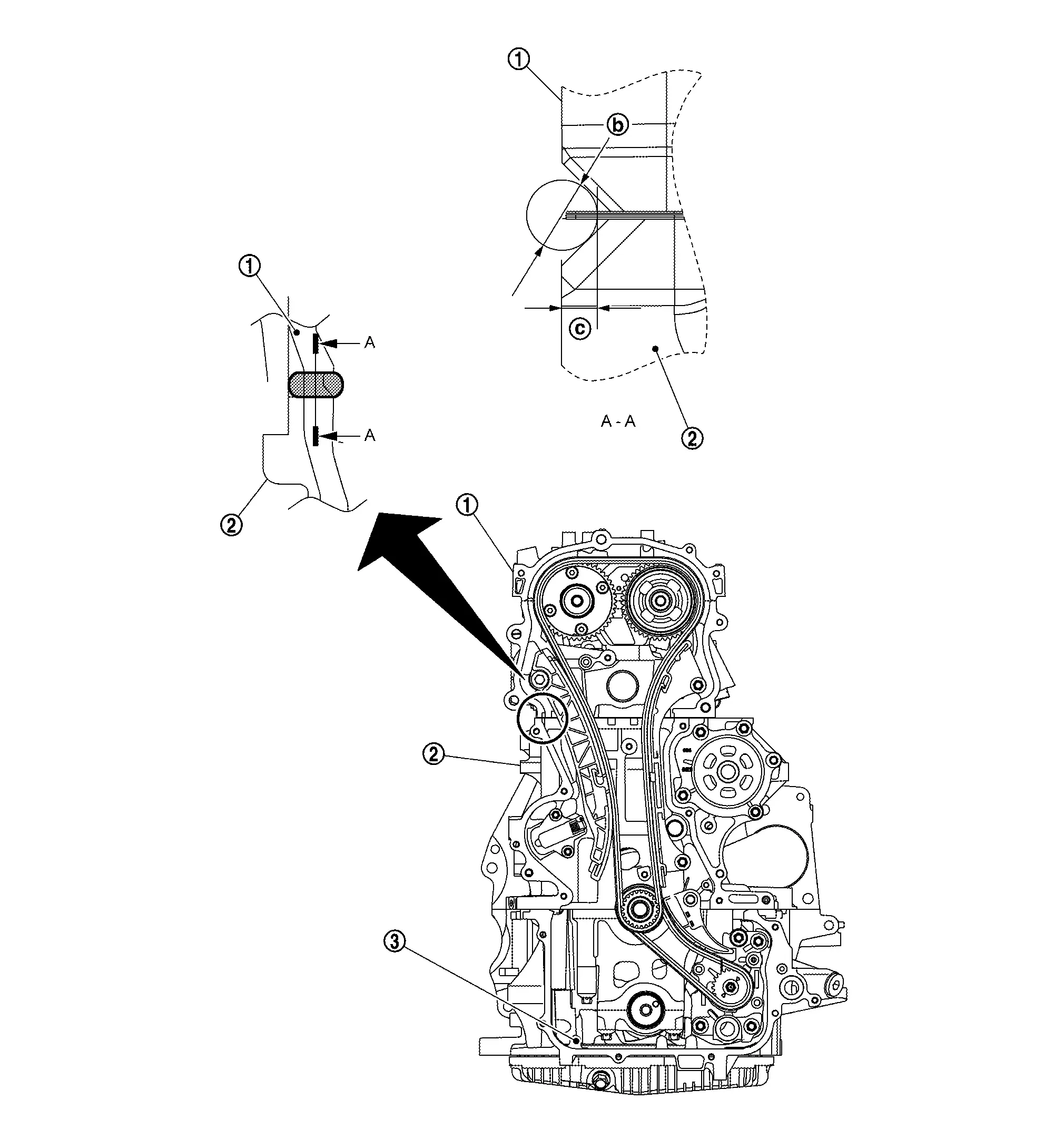
| 1. | Cylinder head | 2. | Cylinder block | 3. | Oil pan upper |
| b | φ 7.2 – 14.0 mm | C | 3.6 mm |
-
Use Genuine RTV Silicone Sealant or an equivalent. Refer to Recommended Chemical Products and Sealants.
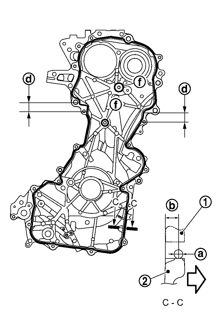
| a | : φ2.7 – 3.7 mm (0.106 – 0.146 in) |
| b | : 4.0 – 5.6 mm (0.157 – 0.222 in) |
| d | : 30 mm (1.18 in) Apply liquid gasket φ6.0 – 7.0 mm (0.236 – 0.146 in) between this area. |
| E | : Liquid gasket |
| f | : 11.8 - 13.4 mm (0.465 - 0.528 in) |
|
: Engine outer side |
-
Refer to the following for the installation position of bolts.
No. 1, 2, 3, 4, 5, 6, 7, 10, 11, 13, 14, 15, 16, 17, 18, 19, 21, 22, 23, 24 : 10.0 N·m (1.0 kg-m, 89 in-lb) No. 8, 9, 12, 20 : 55.0 N·m (5.6 kg-m, 41 ft-lb)
CAUTION:
-
The components must be installed within 5 minutes of the liquid gasket application.
-
Be sure to wipe off any excessive liquid gasket.
Install valve timing control cover using the following procedure:Install new O-rings onto valve timing control cover.
CAUTION:
Do not reuse O-rings.
Tighten the valve timing control cover bolts to the specified torque in the sequence shown.
Install exhaust valve timing control solenoid valve.
Install electric valve timing control actuator.
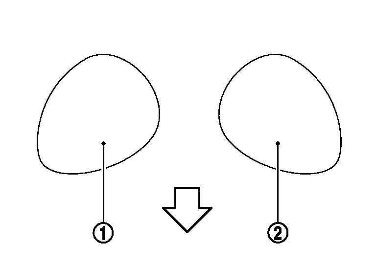
Install crankshaft pulley using the following procedure:Align holes in crankshaft pulley damper (1) with pins in crankshaft pulley (2) and press until click sound is heard from circlip (B).
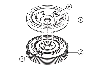
| (A) | : Crankshaft key position indicator |
CAUTION:
Do not damage front oil seal lip portion.
Secure crankshaft pulley with a pulley holder. Apply new engine oil to thread and seat surfaces of crankshaft pulley bolt. Tighten crankshaft pulley bolt to the specified torque.| Crankshaft pulley bolt | : 29.4 N·m (3.0 kg-m, 22 ft-lb) |
CAUTION:
Check and confirm the tightening angle using angle wrench [SST: KV10112100 (BT8653-A)]. Avoid judgment by visual inspection without Tool.
| Tightening angle | : 100° - 106° |
Installation of the remaining components is in the reverse order of removal.
CAUTION:
-
If timing chain removed or replaced, perform "ELECTRIC IVT CONTROL ACTUATOR POSITION LEARNING". Refer to Description.
-
If intake/exhaust camshaft sprocket removed or replaced, perform "ELECTRIC IVT CONTROL ACTUATOR POSITION LEARNING". Refer to Description.
VALVE TIMING CONTROL COVER
REMOVAL
Remove front tire (RH). Refer to Removal and Installation.
Remove splash guard. Refer to Removal and Installation.
Disconnect harness connectors from exhaust valve timing control solenoid valve.
Remove exhaust valve timing control solenoid valve.
Support the engine and transaxle using a suitable jack.
CAUTION:
-
Do not damage oil pan (lower) or transaxle oil pan when supporting engine.
-
Place piece of wood or equivalent as the supporting surface and secure in a stable condition.
Remove engine mounting insulator (RH). Refer to Removal and Installation.
Loosen valve timing control cover bolts in reverse of the sequence shown and remove valve timing control cover.
CAUTION:
-
Do not damage mating surface.
-
The liquid gasket used at the factory is very strong, remove valve timing control cover using a suitable tool.
-
Do not reuse filter or O-rings.
INSTALLATION
Installation in the reverse order of removal.
Inspection
INSPECTION AFTER REMOVAL
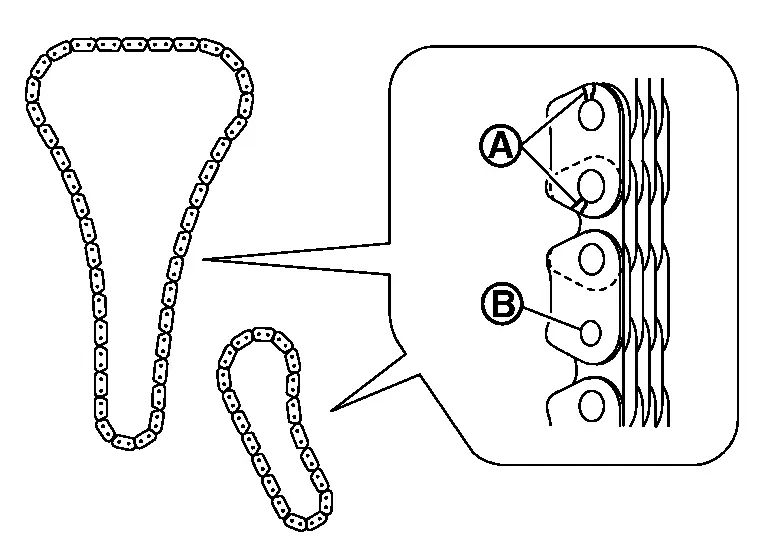
Timing Chain
Check for cracks  and any excessive wear
  at link plates and roller links of timing chain.
Replace timing chain if necessary.
.
INSPECTION AFTER INSTALLATION
Inspection for Leakage
The following are procedures for checking fluid leakage, lubricant leakage, and exhaust gas leakage.
-
Before starting engine, check oil/fluid levels including engine coolant and engine oil. If less than required quantity, fill to the specified level. Refer to Fluids and Lubricants.
-
Use procedure below to check for fuel leakage:
-
Turn ignition switch “ON” (with engine stopped). With fuel pressure applied to fuel piping, check for fuel leakage at connection points.
-
Start engine. With engine speed increased, check again for fuel leakage at connection points.
-
-
Run engine to check for unusual noise and vibration.
NOTE:
If hydraulic pressure inside timing chain tensioner drops after removal/installation, slack in guide may generate a pounding noise during and just after the engine start. However, this does not indicate an unusualness. Noise will stop after hydraulic pressure rises.
-
Warm up engine thoroughly to check that there is no leakage of fuel, or any oil/fluids including engine oil and engine coolant.
-
Bleed air from lines and hoses of applicable lines, such as in cooling system.
-
After cooling down engine, again check oil/fluid levels including engine oil and engine coolant. Refill to the specified level, if necessary.
Summary of the inspection items: Items Before starting engine Engine running After engine stopped Engine coolant Level Leakage Level Engine oil Level Leakage Level Transmission / transaxle fluid AT & CVT Models Leakage Level / Leakage Leakage MT Models Level / Leakage Leakage Level / Leakage Other oils and fluids* Level Leakage Level Fuel Leakage Leakage Leakage Exhaust gases — Leakage — *: Power steering fluid, brake fluid, etc.
Other materials:
P0011 Ivt Control
DTC Description
DTC DETECTION LOGIC DTC
CONSULT screen terms
(Trouble diagnosis content)
DTC detection condition
P0011
00
INT/V TIM CONT-B1
(“A” Camshaft position - timing over-advanced or system performance bank 1)
Diagnosis condition
Engine running
Signal (term ...
Engine oil
Checking engine oil level
Park the vehicle on a level area and apply the parking brake.
Warm up the engine to operating temperature.
Shut the engine off and wait at least 10 minutes.
Remove the dipstick, wipe it clean, then fully reinsert it.
Remove the dipstick again and check the oil le ...
Dtc/circuit Diagnosis. U1327-52 Mac Key Update
DTC Description
DTC DETECTION LOGIC DTC No.
CONSULT screen items
(Trouble diagnosis content) DTC Detection Condition
U1327-52
MAC key update
(Message authentication code key update)
Diagnosis condition
-
Signal (terminal)
-
Threshold
MAC key writing is incomplete. ...