Nissan Rogue (T33) 2021-Present Service Manual: Camshaft
Exploded View
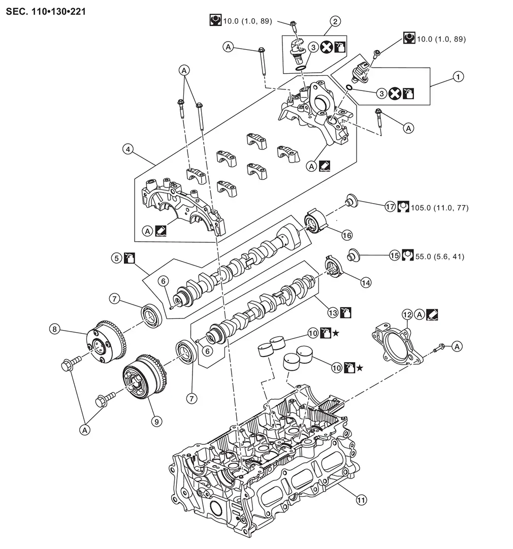
| 1. | Intake camshaft position sensor | 2. | Exhaust camshaft position sensor | 3. | O-ring |
| 4. | Camshaft bracket | 5. | Camshaft (EXH) | 6. | Dowel pin |
| 7. | Camshaft bearing | 8. | Camshaft sprocket (EXH) | 9. | Camshaft sprocket (INT) |
| 10. | Valve lifter | 11. | Cylinder head | 12. | Rear camshaft bracket |
| 13. | Camshaft (INT) | 14. | Signal plate (INT) | 15. | Signal plate bolt |
| 16. | Signal plate (EXH) | 17. | Signal plate bolt | A. | Refer to Removal and Installation. |
 |
: Select with proper thickness. | ||||
Removal and Installation
CAUTION:
The rotating direction in the text indicates all directions seen from the engine front.
REMOVAL
Remove the intake manifold. Refer to Removal and Installation.
Remove the multi-way control valve. Refer to Removal and Installation.
Remove the high pressure fuel pump. Refer to Removal and Installation.
For models without ProPILOT Assist 2.1, remove the vacuum pump. Refer to Removal and Installation.
For models with ProPILOT Assist 2.1, remove bolts in reverse of the sequence shown and remove the rear camshaft bracket.
Remove the front cover and timing chain. Refer to Removal and Installation.
 NOTE:
NOTE:
Removal of oil pump drive related part is not necessary.
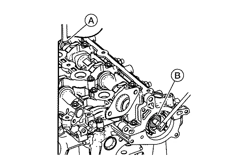
Remove oil feed tube mounting bolt  .
.
Remove heat insulator  .
.
Remove oil feed tube  .
.
Remove the electric valve timing control actuator target from the camshaft sprocket (INT).
CAUTION:
Do not reuse electric valve timing control actuator target.
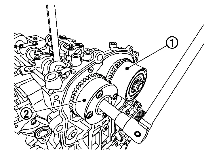
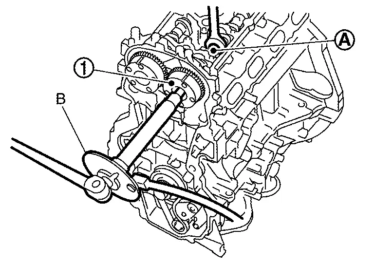
Secure the hexagonal part of the camshaft using a suitable tool and remove the bolts and camshaft sprockets [INT  and EXH ].
CAUTION:
-
Do not rotate crankshaft or camshaft while timing chain is removed. It causes interference between valve and piston.
-
When loosening the bolts, do not secure the camshaft with anything other than the camshaft hexagonal part or with tensioning the timing chain.
If necessary, secure the hexagonal part of the camshaft (EXH) and remove the bolt  for the signal plate (EXH).
Remove the EGR cooler. Refer to Removal and Installation.
Remove cover (right) mounting bolt .
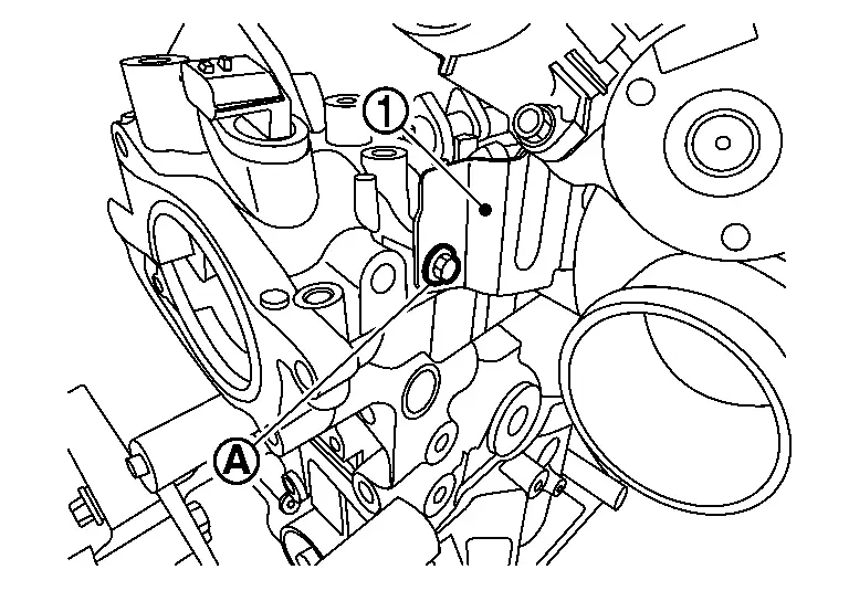
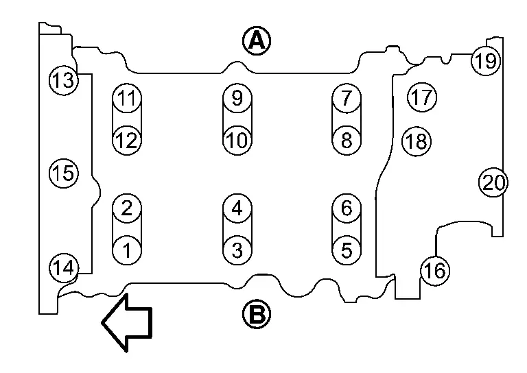
Remove camshaft bracket using the following procedure:Loosen camshaft bracket bolts in reverse of the sequence shown.
|
: Exhaust side |
|
: Intake side |
 |
: Engine front |
CAUTION:
-
Do not damage the mating surface.
-
The liquid gasket used at the factory is very strong. Pry only in the areas shown.
Remove camshafts.
Remove valve lifters (if necessary).
-
Identify installation positions, and store them without mixing them up.
Remove signal plate (INT) from camshaft (if necessary).
Remove camshaft bearing (if necessary).
INSTALLATION
CAUTION:
Do not reuse O-rings.
Install valve lifters (if necessary).
-
Install them in the original positions.
Install the signal plate (INT) (if necessary).
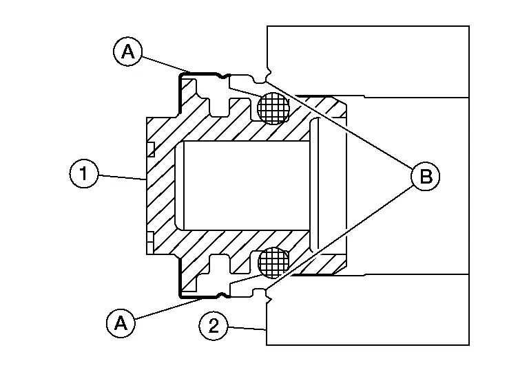
Press the camshaft bearing until it hits the camshaft mounting surface to mount it.
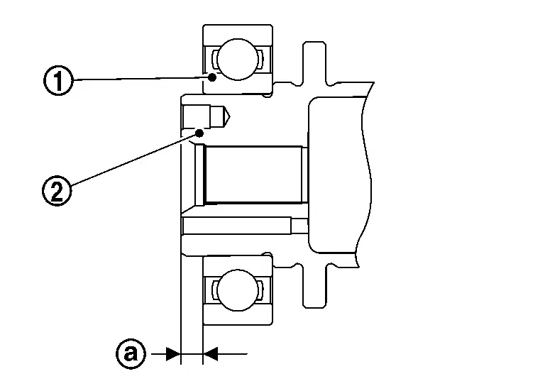
 |
: 3.3 â 4.0 mm (0.13 â 0.16 in) |
|
: Camshaft |
NOTE:
Check that the camshaft bearing is as shown in the figure.
Install camshafts.
-
Clean camshaft journal to remove any foreign material.
-
Distinguish between the camshaft (INT)
and the camshaft (EXH) by looking at the different shapes of the front and rear ends of the camshaft or using the identification colors or .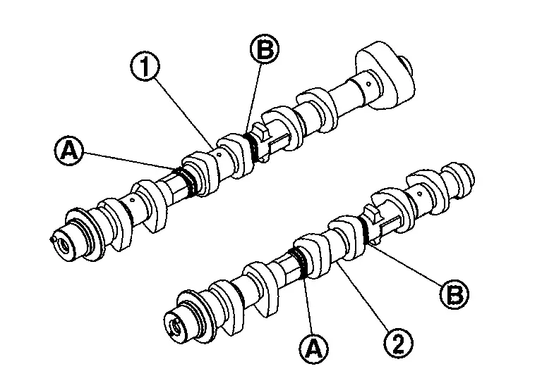
Identification color Camshaft (EXH) â Yellow Camshaft (INT) Yellow â -
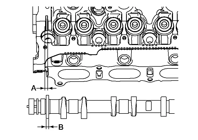
Install camshafts so that camshaft dowel pins
on the front side are positioned as shown. NOTE:
NOTE:
Though camshaft does not stop at the positions as shown, for the placement of cam nose, it is generally accepted camshaft is placed for the same direction of the figure.
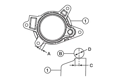
Install camshaft bracket using the following procedure:Remove foreign
material completely from camshaft bracket backside and from cylinder
head installation face. Apply a bead of liquid gasket to camshaft
bracket as shown.
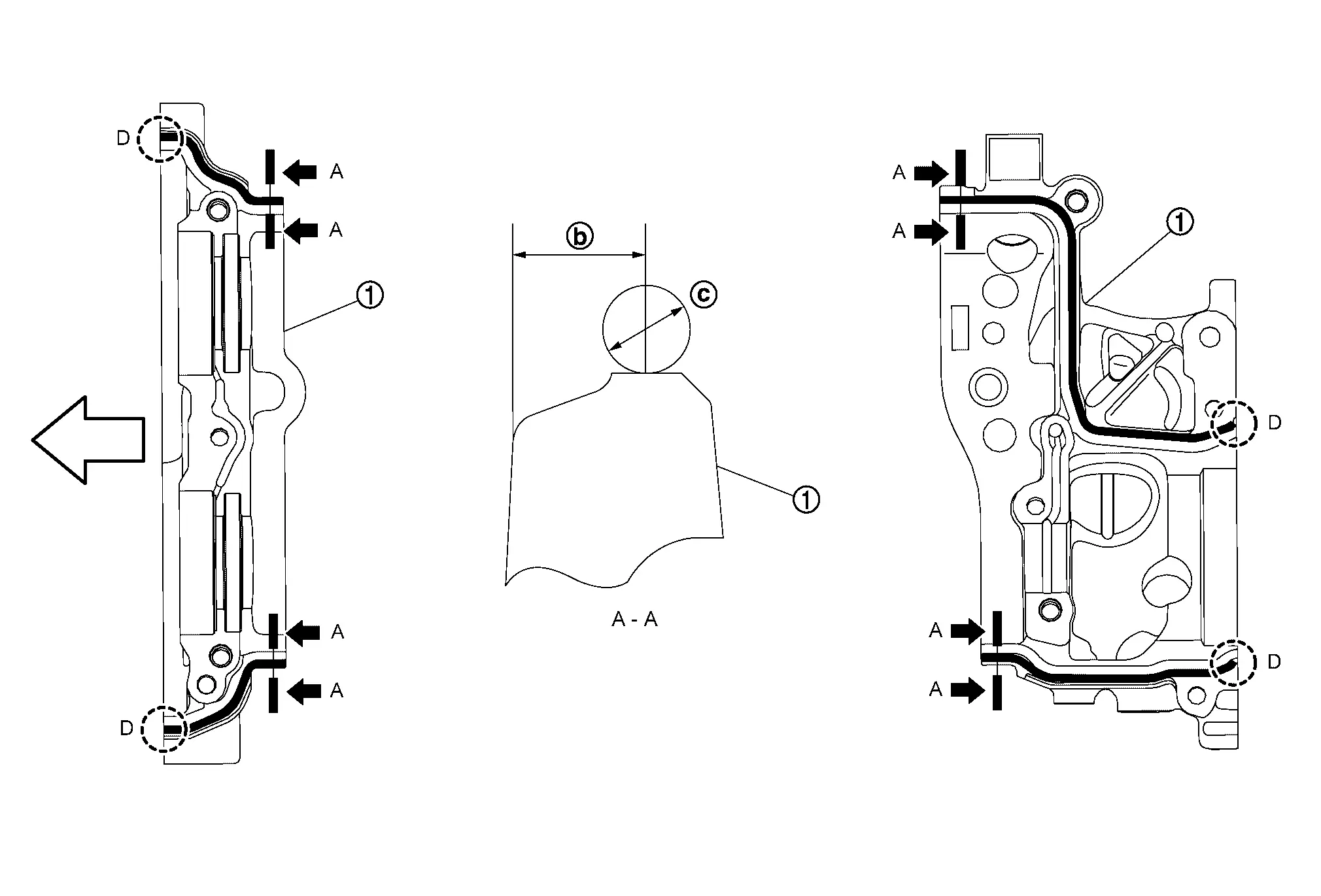
|
: Camshaft bracket |
 |
: 4.0 â 5.6 mm (0.16 â 0.22 in) |
 |
: 2.7 â 3.7 mm (0.106 â 0.146 in) |
| D | : Remove liquid gasket hat protrudes at locations shown. |
|
: Engine front |
Use Genuine RTV Silicone Sealant or an equivalent. Refer toRecommended Chemical Products and Sealants.
CAUTION:
-
The components must be installed within 5 minutes of the liquid gasket application.
-
Do not re-tighten bolts after the 5 minutes have elapsed.
-
Allow 30 minutes for the liquid gasket to set before adding oil to the engine.
NOTE:
Remove liquid gasket that protrudes at locations ( ) shown.
-
Install the No. 2 to No. 4 camshaft brackets by referring to the identification symbol on the topãsurface.
: EXH side : INT side : Engine front -
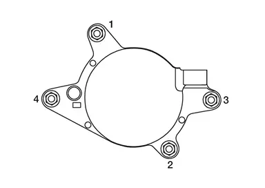
Tighten camshaft bracket bolts to the specified torque in the sequence shown using the following procedure.
: EXH side : INT side : Engine front
| Step 1 | : 1.96 N·m (0.20 kg-m, 17 in-lb) |
| Step 2 | : 5.88 N·m (0.60 kg-m, 52 in-lb |
| Step 3 | : 10.41N·m (1.1 kg-m, 8 ft-lb) |
Install the camshaft sprocket to the camshaft using the following procedure:Tighten camshaft sprocket bolts using the following steps:
-
Secure the hexagonal part of camshaft using a angle wrench [SST: KV10112100 (BT8653-A)] (B). to tighten camshaft sprocket bolt.
-
Tighten camshaft sprocket bolt to the specified torque.
Camshaft sprocket bolt : 35.0 N·m (3.6 kg-m, 26 ft-lb) -
Tighten camshaft sprocket bolt by the specified angle.
CAUTION:
Check the tightening angle by using angle wrench [SST: KV10112100 (BT8653-A)] (B). Do not judge by visual inspection without Tool.
Tightening angle : 28° - 33° : Camshaft sprocket : Camshaft hexagonal part
Install timing chain and related parts. Refer to Removal and Installation.
Install the electric valve timing control actuator target into the camshaft sprocket (INT) until the metal ring clips into the groove in the sprocket.
CAUTION:
Do not reuse electric valve timing control actuator target.
NOTE:
Apply new engine oil to the electric valve timing control actuator target O-ring if necessary. Make sure that no engine oil adheres to front face of camshaft sprocket (INT).
|
: Electric valve timing control actuator target |
|
: Electric valve timing control actuator |
If removed, install the signal plate (EXH) by securing the hexagonal part of the camshaft (EXH).
NOTE:
The signal plate (EXH) can only be installed in one orientation, make sure to align tabs on signal plate (EXH) with grooves in camshaft (EXH).
|
: Signal plate bolt |
Install high pressure fuel pump. Refer to Removal and Installation.
Install the union bolt for the turbocharger oil supply line. Refer to Removal and Installation.
Install the multi-way control valve. Refer to Removal and Installation.
For models without ProPILOT Assist 2.1, install the vacuum pump. Refer to Removal and Installation.
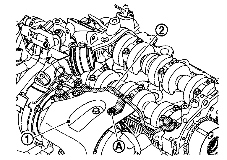
For models with ProPILOT Assist 2.1, install the rear camshaft bracket using the following procedure:Remove foreign material completely from rear camshaft bracket backside and from cylinder head installation face. Apply a bead of liquid gasket (B) to rear camshaft bracket (1) as shown.
| (A) | : Location for overlap of liquid gasket |
| (C) | : 0.5 â 2.1 mm (0.020 â 0.083 in) |
| (D) | : 3.4 â 4.4 mm (0.134 â 0.173 in) |
Use Genuine RTV Silicone Sealant or an equivalent. Refer toRecommended Chemical Products and Sealants.
CAUTION:
-
The components must be installed within 5 minutes of the liquid gasket application.
-
Do not re-tighten bolts after the 5 minutes have elapsed.
-
Allow 30 minutes for the liquid gasket to set before adding oil to the engine.
| Rear camshaft bracket bolts | : 10.0 N·m (1.0 kg-m, 89 in-lb) |
Inspect and adjust valve clearance. Refer to Inspection and Adjustment.
Installation of the remaining components is in the reverse order of removal.
CAUTION:
-
If intake/exhaust camshaft sprocket removed or replaced, perform "ELECTRIC IVT CONTROL ACTUATOR POSITION LEARNING". Refer to Description.
-
If intake/exhaust camshaft removed or replaced, perform "ELECTRIC IVT CONTROL ACTUATOR POSITION LEARNING". Refer to Description.
-
If intake camshaft position sensor replaced, perform "ELECTRIC IVT CONTROL ACTUATOR POSITION LEARNING". Refer to Description.
-
If exhaust camshaft position sensor replaced, perform "ELECTRIC IVT CONTROL ACTUATOR POSITION LEARNING". Refer to Description.
Inspection
INSPECTION AFTER REMOVAL
Camshaft Runout
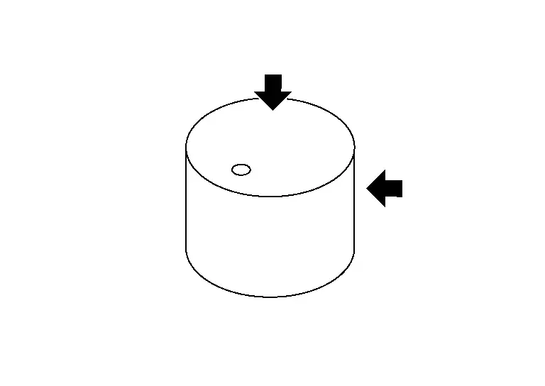
Put V-block on a precise flat table, and support No. 2 and 5 journal of camshaft.
CAUTION:
Do not support No. 1 journal (on the side of camshaft sprocket) because it has a different diameter from the other four locations.
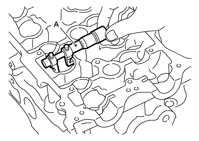
Set suitable tool (A) vertically to No. 3 journal.
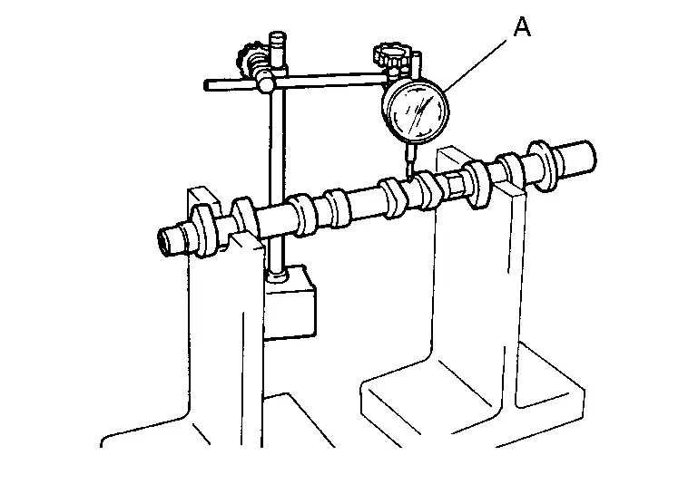
Turn camshaft to one direction with hands, and measure the camshaft runout on suitable tool. (Total indicator reading)
| Standard and Limit | : Camshaft. |
If it exceeds the limit, replace camshaft.
Camshaft Cam Height
Measure the camshaft cam height with a suitable tool (A).
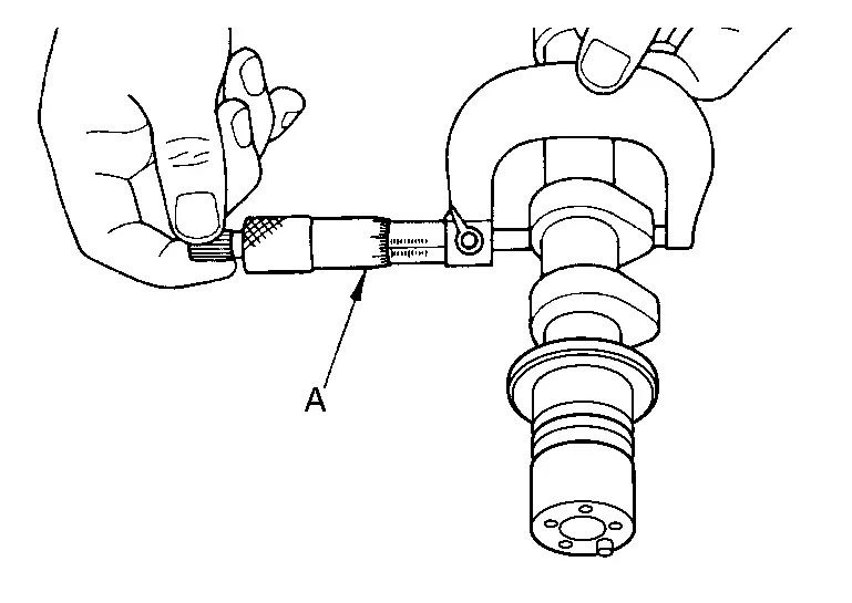
| Standard and Limit | : Refer to Camshaft. |
If it exceeds the limit, replace camshaft.
Camshaft Journal Oil Clearance
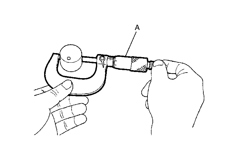
CAMSHAFT JOURNAL OUTER DIAMETER
Measure the outer diameter of camshaft journal with a suitable tool (A).
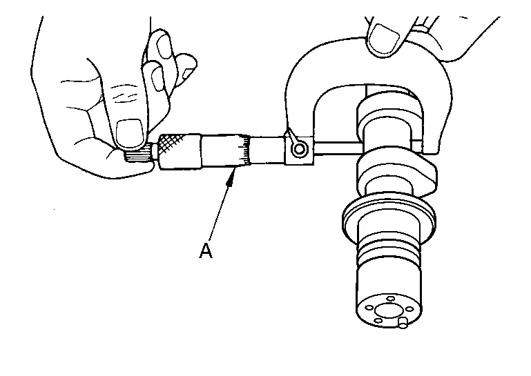
| Standard | : Refer to Camshaft. |
CAMSHAFT BRACKET INNER DIAMETER
-
Tighten camshaft bracket bolts to specified torque. Refer to Removal and Installation.
-
Measure the inner diameter of camshaft bracket with a suitable tool (A).
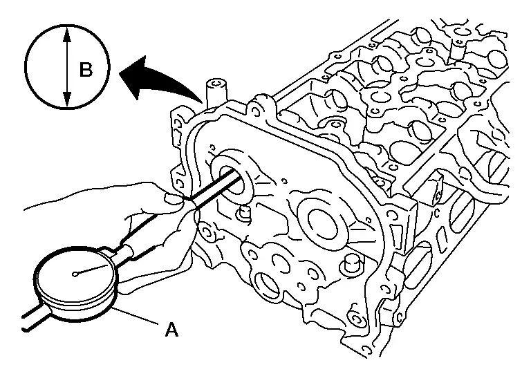
Standard : Refer to Camshaft. (B) : Measuring direction of inner diameter
CAMSHAFT JOURNAL OIL CLEARANCE
-
(Oil clearance) = (Camshaft bracket inner diameter) â (Camshaft journal diameter)
Standard and Limit : Refer to Camshaft. -
If it exceeds the limit, replace camshaft or cylinder head, or both.
NOTE:
Camshaft bracket cannot be replaced as a single part, because it is machined together with cylinder head. Replace whole cylinder head assembly.
Camshaft End Play
Install camshaft in cylinder head. Refer to Removal and Installation.
Install suitable tool in thrust direction on front end of camshaft. Read the end play of suitable tool (A) when camshaft is moved forward/backward (in direction to axis).
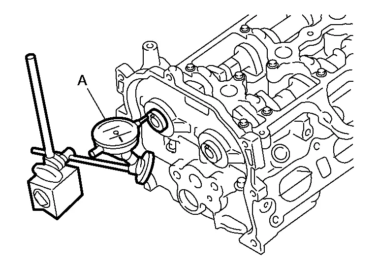
| Standard and Limit | : Refer to Camshaft. |
-
Measure the following parts if out of the standard:
-
Dimension (A) for groove of cylinder head No. 1 journal
Standard : 4.000 - 4.030 mm (0.1575 - 0.1587 in) -
Dimension (B) for camshaft flange
Standard : 3.877 - 3.925 mm (0.1526 - 0.1545 in)
-
-
Refer to the standards above, and then replace camshaft and/or cylinder head.
Camshaft Sprocket Runout
Put V-block on precise flat table, and support No. 2 and 5 journals of camshaft.
CAUTION:
Do not support No. 1 journal (on the side of camshaft sprocket) because it has a different diameter from the other four locations.
Measure the camshaft sprocket runout with a suitable tool (A). (Total indicator reading)
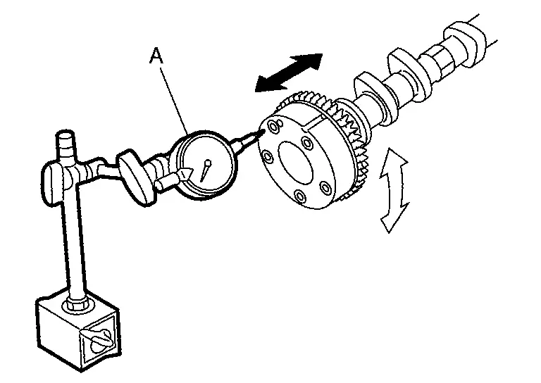
| Limit | : Refer to Camshaft . |
-
If it exceeds the limit, replace camshaft sprocket.
Valve Lifter
Check if surface of valve lifter has any wear or cracks.
-
If anything above is found, replace valve lifter. Refer to Camshaft.
Valve Lifter Clearance
VALVE LIFTER OUTER DIAMETER
-
Measure the outer diameter of valve lifter with a suitable tool (A).
Standard : Refer to Camshaft.
VALVE LIFTER HOLE DIAMETER
Measure the inner diameter of valve lifter hole of cylinder head with a suitable tool (A).
| Standard | : Refer to Camshaft. |
VALVE LIFTER CLEARANCE
-
(Valve lifter clearance) = (Valve lifter hole diameter) â (Valve lifter outer diameter)
Standard : Camshaft. -
If out of the standard, referring to the standard of valve lifter outer diameter and valve lifter hole diameter, replace either or both valve lifter and cylinder head.
INSPECTION AFTER INSTALLATION
Inspection of Camshaft Sprocket (EXH) Oil Groove
CAUTION:
-
Perform this inspection only when DTC P0014 is detected in self-diagnostic results of CONSULT and it is directed according to inspection procedure of EC section. Refer to DTC Description. (P0014)
-
Check when engine is cold so as to prevent burns by the splashing engine oil.
Check engine oil level. Refer to Inspection.
Perform the following procedure so as to prevent the engine from being unintentionally started while checking.Release the fuel pressure. Refer to Work Procedure. Remove intake manifold. Refer to Removal and Installation. Disconnect the harness connectors from the ignition coils and fuel injector. Support the bottom surface of engine using a transmission jack, and then remove the engine mounting bracket (RH) and engine mounting insulator (RH). Refer to Removal and Installation.
Remove exhaust valve timing control solenoid valve. Refer to Removal and Installation.
-
Lift the front side of the engine with a jack base to remove intake or exhaust valve timing control solenoid valve.
Clean the mounting area of intake or exhaust valve timing control solenoid valve, and then insert a clean waste with no oil adhesion into the oil hole of the cylinder head.
Install engine mounting insulator (RH) and engine mounting bracket (RH). (After the removal of intake or exhaust valve timing control solenoid valve and insertion of a waste into the oil hole.)
Perform cranking to check that engine oil comes out from the oil hole (mounting hole of intake or exhaust valve timing control solenoid valve) of cylinder head.
-
Regarding the engine oil check, judge it by the amount of oil adhered to the waste inserted into the oil hole.
WARNING:
-
Do not insert fingers into the oil hole.
-
Do not touch rotating parts (crankshaft pulley, etc.).
CAUTION:
-
Do not perform cranking without installing the engine mounting insulator (RH) and engine mounting bracket (RH).
-
Prevent splashing by using a shop cloth so as to prevent the worker from injury from engine oil and so as to prevent engine oil contamination.
-
Prevent splashing by using a shop cloth so as to prevent engine oil from being splashed to engine and Nissan Ariya vehicle. Especially, be careful not to apply engine oil to rubber parts of engine mounting insulator, etc. Wipe engine oil off immediately if it is splashed.
Perform the following inspection if engine oil does not come out from intake or exhaust valve timing control solenoid valve oil hole of the cylinder head.
-
Clean oil groove between oil strainer and exhaust valve timing control solenoid valve. Refer to Engine Lubrication System.
Remove components between exhaust valve timing control solenoid valve and camshaft sprocket (EXH), and then check each oil groove for clogging.
-
Clean oil groove if necessary. Refer to Engine Lubrication System.
After inspection, installation is in the reverse order removal.
INSPECTION AFTER INSTALLATION
Inspection for Leakage
The following are procedures for checking fluid leakage, lubricant leakage, and exhaust gas leakage.
-
Before starting engine, check oil/fluid levels including engine coolant and engine oil. If less than required quantity, fill to the specified level. Refer to Fluids and Lubricants.
-
Use procedure below to check for fuel leakage:
-
Turn ignition switch âONâ (with engine stopped). With fuel pressure applied to fuel piping, check for fuel leakage at connection points.
-
Start engine. With engine speed increased, check again for fuel leakage at connection points.
-
-
Run engine to check for unusual noise and vibration.
NOTE:
If hydraulic pressure inside timing chain tensioner drops after removal/installation, slack in guide may generate a pounding noise during and just after the engine start. However, this does not indicate an unusualness. Noise will stop after hydraulic pressure rises.
-
Warm up engine thoroughly to check that there is no leakage of fuel, or any oil/fluids including engine oil and engine coolant.
-
Bleed air from lines and hoses of applicable lines, such as in cooling system.
-
After cooling down engine, again check oil/fluid levels including engine oil and engine coolant. Refill to the specified level, if necessary.
Summary of the inspection items: Items Before starting engine Engine running After engine stopped Engine coolant Level Leakage Level Engine oil Level Leakage Level Transmission / transaxle fluid AT & CVT Models Leakage Level / Leakage Leakage MT Models Level / Leakage Leakage Level / Leakage Other oils and fluids* Level Leakage Level Fuel Leakage Leakage Leakage Exhaust gases â Leakage â *: Power steering fluid, brake fluid, etc.
Other materials:
Dtc/circuit Diagnosis. Drive Mode Select Switch Circuit
Diagnosis Procedure
CHECK DRIVE MODE SELECT SWITCH SIGNAL CIRCUIT
Ignition switch OFF.
Disconnect drive mode select switch harness connector and BCM harness connector.
Check the continuity between drive mode select switch harness connector and BCM harness connector.
2WD models with ...
Air Cleaner and Air Duct
Exploded View
1.
Air duct (Inlet)
2.
Clip
3.
Mounting rubber
4.
Mounting rubber
5.
Bracket
6.
Clip
7.
Air cleaner body
8.
Mounting rubber
9.
Collar
10.
Air cleaner filter
11.
Air cleaner cover
12.
Mass air flow sensor
...
Fonctionnement du systÃĻme LDW
TÃĐmoin LDW (affichÃĐ sur lâÃĐcran dâinformations du vÃĐhicule)
Ãcran dâinformations du vÃĐhicule
Commandes au volant (cÃītÃĐ gauche)
Le systÃĻme LDW du Nissan Rogue active la fonction dâalerte sortie de voie lorsque la vitesse du vÃĐhicule atteint environ 60 km/h (37 mi ...