Nissan Rogue (T33) 2021-Present Service Manual: Three Way Catalyst
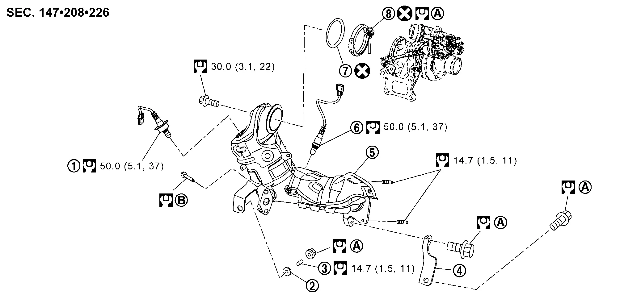
Exploded View
 |
Air fuel ratio (A/F) sensor 1 |  |
Manifold washer |  |
Stud bolt |
 |
Catalyst support bracket |  |
Three way catalyst |  |
Heated oxygen sensor 2 |
 |
Turbo gasket (OUT) |  |
V-band clamp | ||
 |
Comply with the assembly procedure when tightening. Refer to Removal and Installation. |  |
Comply with the assembly procedure when tightening. Refer to Removal and Installation. | ||
 |
: N┬Ęm (kg-m, ft-lb) | ||||
 |
: Always replace after every disassembly. | ||||
Removal and Installation
2WD
REMOVAL
Remove cowl top extension. Refer to Removal and Installation.
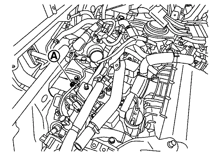
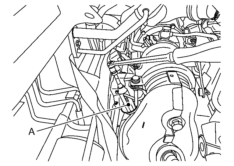
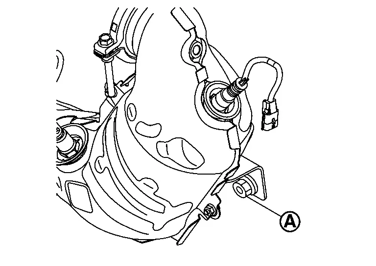
Remove oil feed tube bracket mounting bolt (A).
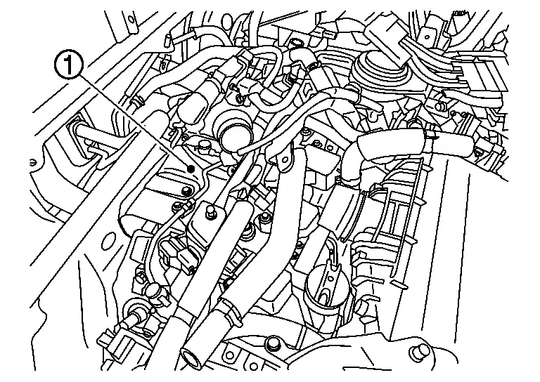
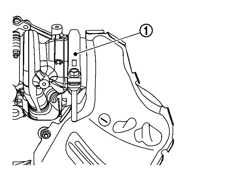
Remove turbocharger heat insulator (1).
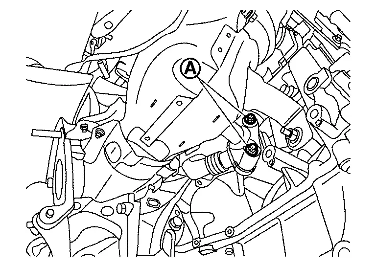
Disconnect the air fuel ratio (A/F) sensor 1 harness connector and then remove the air fuel ratio (A/F) sensor 1 using heated oxygen sensor wrench [SST:KV10117100 (NI-36471-A)] (A).
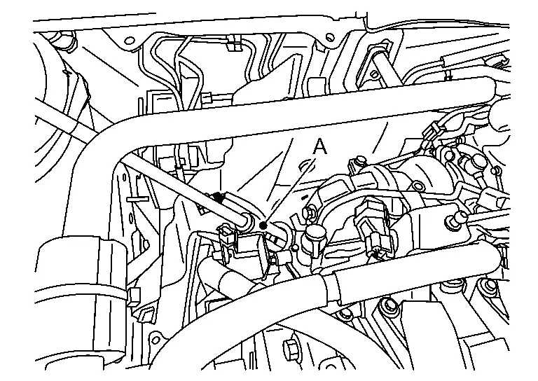
Disconnect the heated oxygen sensor 2 harness connector and then remove the heated oxygen sensor 2 using heated oxygen sensor wrench [SST:KV10117100 (NI-36471-A)] (A).
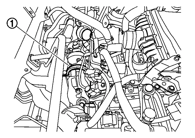
Loosen V-band clamp (1).
Remove front tube. Refer to Exploded View.
Remove drive shaft (RH) . Refer to Removal and Installation.
Remove drive shaft support bearing. Refer to Disassembly and Assembly.
Remove front suspension member. Refer to Removal and Installation.
Remove mounting bolt (A). Refer to Removal and Installation.
Remove catalyst support bracket.
Disconnect three way catalyst mounting nut, and remove from underside of the Nissan Ariya vehicle.
INSTALLATION
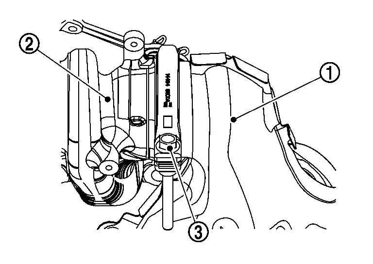
Install the three way catalyst (1) to the turbocharger (2) and hand tighten the V-band clamp (3).
CAUTION:
Do not reuse gasket and V-band clamp.
 NOTE:
NOTE:
Locate mark (A) on turbo charger housing (1) must be in between paints (B) V-band clamp (2).
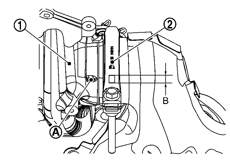
Tighten the nut (A) the temporary tightening.
Tighten the V-band clamp (1) the specified torque.
| V-band clamp |
: 15 N┬Ęm (1.5 kg-m, 11 ft-lb) |
Tighten the nut (A) the specified torque.
| Nut |
: 43.0 N┬Ęm (4.4 kg-m, 32 ft-lb) |
Tighten the catalyst support bracket bolts to the specified torque.
| Catalyst support bracket bolts |
: 50.5 N┬Ęm (5.2 kg-m, 37 ft-lb) |
CAUTION:
-
Before installing the air fuel ratio (A/F) sensor 1 and Heated oxygen sensor 2, clean the threads using oxygen sensor thread cleaner tool and apply anti-seize lubricant or equivalent.
Oxygen sensor thread cleaner :ŌĆāŌĆöŌĆā(NI-43897-18) -
Do not over-tighten the air fuel ratio (A/F) sensor 1 and Heated oxygen sensor 2. Doing so may cause damage, resulting in a malfunction and the MIL coming on.
Install in the reverse order of removal after this step.
AWD
REMOVAL
Remove cowl top extension. Refer to Removal and Installation.
Remove oil feed tube bracket mounting bolt (A).
Remove turbocharger insulator (1).
Disconnect the air fuel ratio (A/F) sensor 1 harness connector and then remove the air fuel ratio (A/F) sensor 1 using heated oxygen sensor wrench [SST:KV10117100 (NI-36471-A)] (A).
Disconnect the heated oxygen sensor 2 harness connector and then remove the heated oxygen sensor 2 using heated oxygen sensor wrench [SST:KV10117100 (NI-36471-A)] (A).
Loosen V-band clamp (1).
Remove front tube. Refer to Exploded View.
Remove propeller shaft.
Remove drive shaft (RH) . Refer to Removal and Installation.
Remove drive shaft support bearing. Refer to Disassembly and Assembly.
Remove transfer.
Remove front suspension member. Refer to Removal and Installation.
Remove mounting bolt (A). Refer to Removal and Installation.
Remove catalyst support bracket.
Disconnect three way catalyst mounting nut, and remove from underside of the Nissan Ariya vehicle.
INSTALLATION
Install the three way catalyst (1) to the turbocharger (2) and hand tighten the V-band clamp (3).
CAUTION:
Do not reuse gasket and V-band clamp.
NOTE:
Locate mark (A) on turbo charger housing (1) must be in between paints (B) V-band clamp (2).
Tighten the nut (A) the temporary tightening.
Tighten the V-band clamp (1) the specified torque.
| V-band clamp |
: 15 N┬Ęm (1.5 kg-m, 11 ft-lb) |
Tighten the nut (A) the specified torque.
| Nut |
: 43.0 N┬Ęm (4.4 kg-m, 32 ft-lb) |
Tighten the catalyst support bracket bolts to the specified torque.
| Catalyst support bracket bolts |
: 50.5 N┬Ęm (5.2 kg-m, 37 ft-lb) |
CAUTION:
-
Before installing the air fuel ratio (A/F) sensor 1 and Heated oxygen sensor 2, clean the threads using oxygen sensor thread cleaner tool and apply anti-seize lubricant or equivalent.
Oxygen sensor thread cleaner :ŌĆāŌĆöŌĆā(NI-43897-18) -
Do not over-tighten the air fuel ratio (A/F) sensor 1 and Heated oxygen sensor 2. Doing so may cause damage, resulting in a malfunction and the MIL coming on.
Install in the reverse order of removal after this step.
Inspection
Check the joint of parts with the engine in running state.
Check that there are no leaks of exhaust gas and abnormal sound.
Other materials:
B3a70 Intelligent Battery Sensor
DTC Description
DTC DETECTION LOGIC DTC
CONSULT screen terms
(Trouble diagnosis content)
DTC detection condition
B3A70
00
IBS Battery Temp Sensor Failure (Open Circuit)
[IBS battery temp sensor failure (Open circuit)]
Diagnosis condition
Ignition switch ON
Batte ...
Trunk
CONSULT Function (BCM - TRUNK)
DATA MONITORNOTE:
The following table includes information (items)
inapplicable to this Nissan Ariya vehicle. For information (items)
applicable to this vehicle, refer to CONSULT display items.
Monitor Item
[Unit] Condition
Back door/trunk lid switch
[O ...
P2128 App Sensor
DTC Description
DTC DETECTION LOGIC DTC
CONSULT screen terms
(Trouble diagnosis content)
DTC detection condition
P2128
00
APP SEN 2/CIRC
(Throttle/Pedal position sensor/switch E circuit high)
Diagnosis condition
Engine running at idle
Signal (terminal)
Accelerator ...