Nissan Rogue (T33) 2021-Present Service Manual: Turbocharger
Exploded View
CAUTION:
Never disassemble or remove components beyond the configuration shown in the figure.
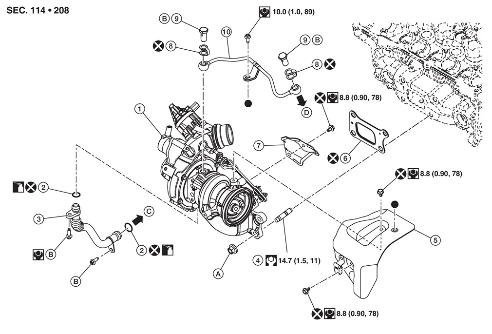
| 1. | Turbocharger | 2. | O-ring | 3. | Turbocharger oil outlet pipe |
| 4. | Stud bolt | 5. | Turbocharger heat insulator 1 | 6. | Turbocharger gasket |
| 7. | Turbocharger heat insulator 2 | 8. | Eye bolt gasket | 9. | Eye bolt |
| 10. | Oil feed tube | A. | Refer to Removal and Installation | B. | Refer to Removal and Installation. |
| C. | To cylinder block. Refer to Exploded View. | D. | To camshaft bracket. Refer to Exploded View. | ||
 |
: Indicates that the parts are connected at points with same symbols in actual Nissan Ariya vehicle. | ||||
Removal and Installation
REMOVAL
Drain engine coolant. Refer to Draining.
Remove air inlet hose. Refer to Removal and Installation.
Remove air duct. Refer to Removal and Installation.
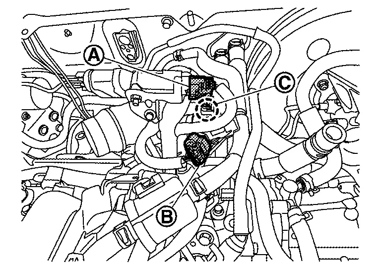
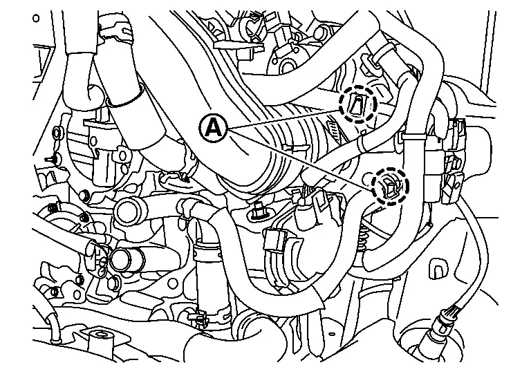
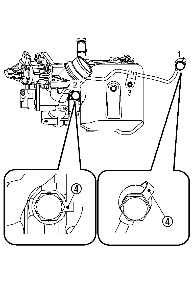
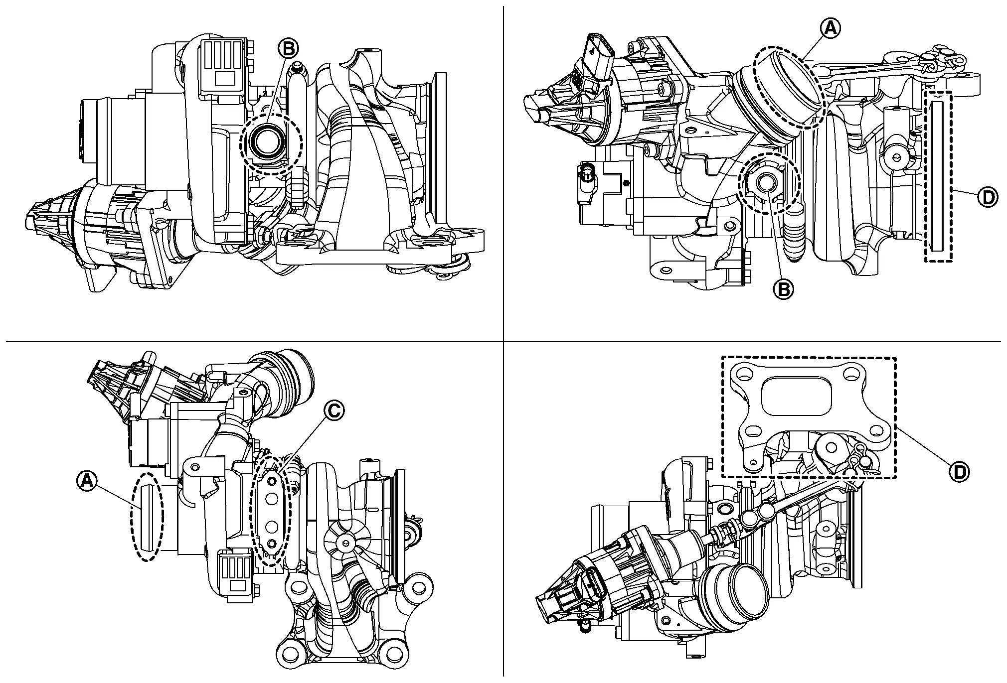
Disconnect EGR differential pressure sensor harness connector (A), turbocharger bypass control valve harness connector (B) and electric wastegate control actuator harness connector (C).
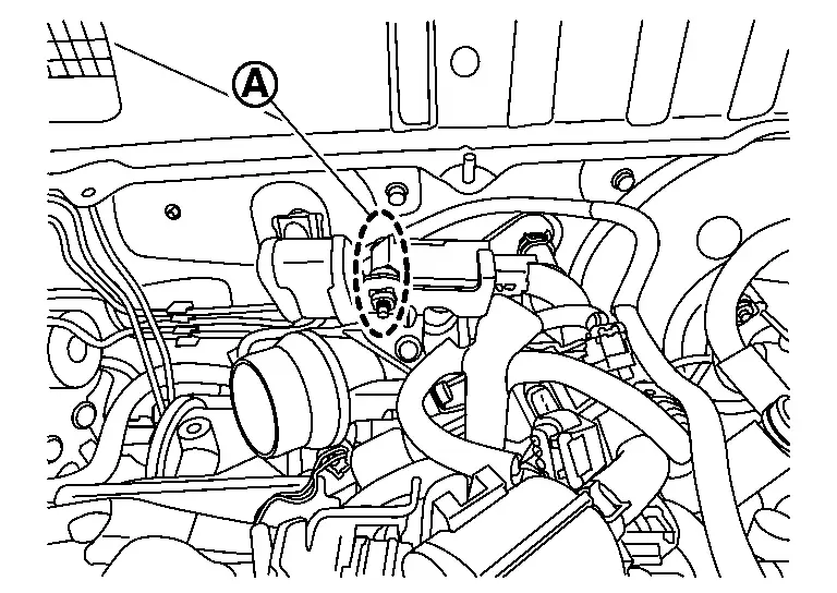
Remove EGR differential pressure sensor mounting bolt (A).
Disconnect harness connector clip and hose in the following procedure.Disconnect the heated oxygen sensor 2 harness connector (B) and EGR temperature sensor harness connector (C).
| A | : Engine back side | ||||
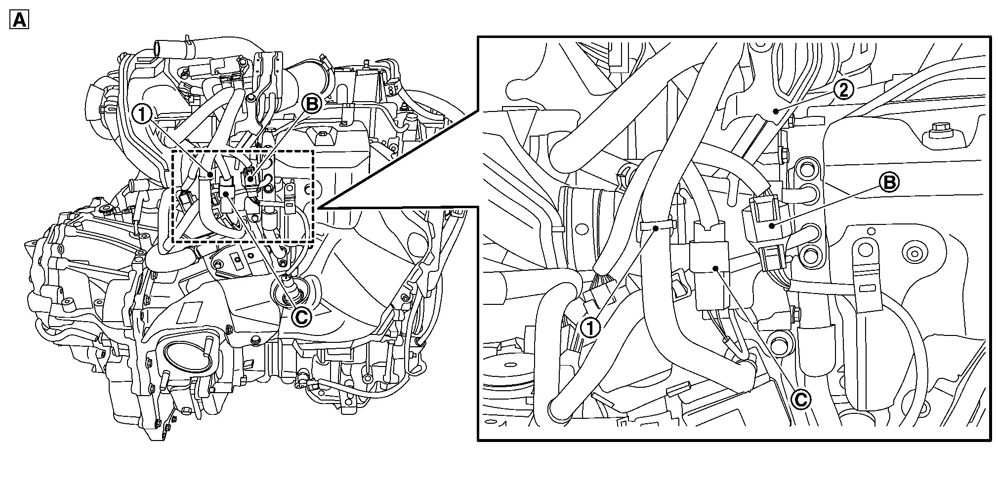
Disconnect water hoses from water pipe bracket side (A).
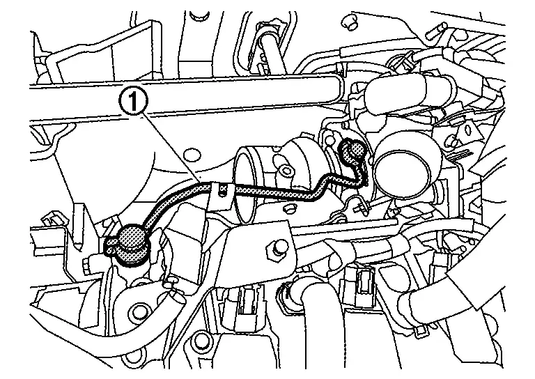
Remove oil pipe (1).
Remove three way catalyst.
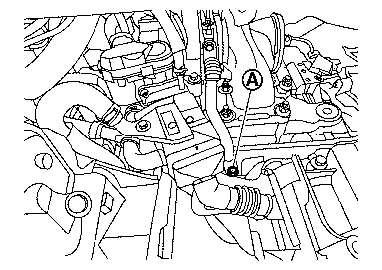
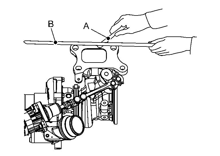
Remove bolt (A) on the underside of the turbocharger oil outlet pipe.
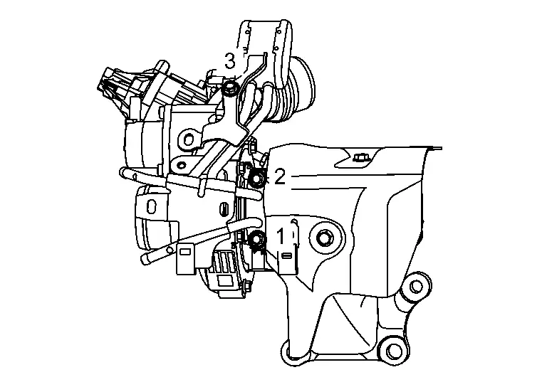
Loosen turbocharger bolts in reverse of the sequence.
CAUTION:
Do not reuse turbocharger gasket.
 NOTE:
NOTE:
Disregard 5, 6, 7, 8 during removal.
Disconnect on the underside of the turbocharger oil outlet pipe from cylinder block.
Remove turbocharger assembly from the underside of the Nissan Ariya vehicle.
CAUTION:
Do not carry or support turbocharger assembly from electric wastegate control actuator, electric wastegate control rod, electric wastegate control lever or turbocharger bypass control valve because damage to turbocharger assembly could occur.
Disconnect mounting bolt on the turbocharger assembly side of the turbocharger oil outlet pipe, and remove the turbocharger oil outlet pipe.
If necessary, remove the water pipe bracket.
CAUTION:
Do not reuse eye bolt gaskets.
INSTALLATION
Note the following and install in the reverse order of removal.
CAUTION:
-
Do not reuse eye bolt gaskets.
-
Do not reuse air inlet tube gasket.
-
Do not reuse oil outlet tube gasket.
-
Do not reuse O-ring.
-
If turbocharger has been replaced, perform "TURBOCHARGER WASTEGATE CONTROL SOLENOID VALVE DATA INITIALIZATION" and use CONSULT to individually check the functions of the turbocharger system. (TURBOCHARGER WASTEGATE CONTROL SOLENOID VALVE DATA INITIALIZATION)
-
TURBOCHARGER WASTEGATE CONTROL SOLENOID VALVE DATA INITIALIZATION: Refer to Description.
-
Individually check: Refer to Component Inspection.
-
-
Check the engine oil level. Refer to Inspection.
-
Refill the engine coolant. Refilling.
-
If the air fuel (A/F) ratio sensor 1 is replaced, perform "AIR FUEL RATIO INITIAL LEARNING". Refer to Description.
-
Tighten the turbocharger nuts to the specified torque in the sequence shown.
CAUTION:
Do not reuse turbocharger gasket.
Turbocharger nuts 
: 30.5 N·m (3.1 kg-m, 22 ft-lb) -
Install the turbocharger oil outlet pipe to turbocharger.
NOTE:
Apply clean engine oil to O-ring before installing turbocharger oil outlet pipe.
Turbocharger oil outlet pipe bolt : 10 N·m (1.0 kg-m, 89 in-lb) -
Tighten the turbocharger oil outlet pipe bolt to cylinder block side.
NOTE:
Apply clean engine oil to O-ring before installing turbocharger oil outlet pipe.
Turbocharger oil outlet pipe bolt : 10 N·m (1.0 kg-m, 89 in-lb) -
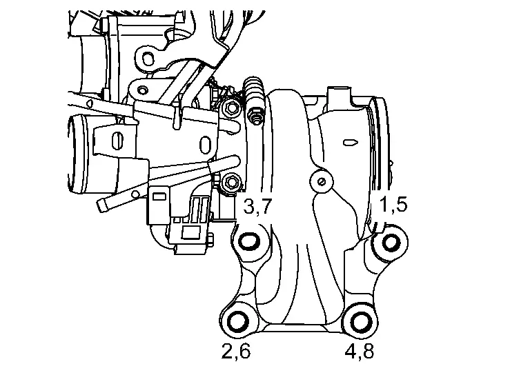
Install the oil feed tube as follows:
-
Tighten eye bolts in order number of as shown in the figure (temporary).
 NOTE:
NOTE:
When tightening the eye bolts, make sure the eye bolt gaskets (4) are in the positions as shown in the figure.
-
Tighten eye bolts in order number of as shown in the figure (specified torque).
NOTE:
When tightening the eye bolts, make sure the eye bolt gaskets (4) are in the positions as shown in the figure.
Oil feed tube eye bolt : 25.0 N·m (2.6 kg-m, 18ft-lb)
-
-
Tighten the water pipe 3 to the specified torque in the sequence shown.
CAUTION:
Do not reuse turbocharger gasket.
Turbocharger nuts 
: 10.0 N·m (1.0 kg-m, 89 in-lb)
Inspection
INSPECTION PROCEDURE
Turbocharger Trouble Diagnosis [Oil Leaks, Smoke (white/blue), Lack of Power, Poor Acceleration, Unusual Noise]
Check that the engine oil amount is the specified level.
Interview the customer about whether the engine oil is cooled down by idling after driving.
Diagnosis
-
Refer to the table below and check each of the parts.
-
For the inspection methods, refer to "INSPECTION AFTER REMOVAL."
| Inspection location | Check result | Symptoms likely to occur when the results shown on the left exist. | |||
| Oil leaks | Smoke | Noise |
Low power Poor acceleration |
||
| Turbine wheel | Oil is leaking. |  |
 |
|
|
| Carbon deposits are observed. | |
|
 |
|
|
| There are marks from rubbing against housing. | |
|
|
|
|
| Vane is bent or broken. | |
|
|||
| Compressor wheel | Inside of intake port is badly stained with oil. | |
|
||
| There are marks from rubbing against housing. | |
|
|
|
|
| Vane is bent or broken. | |
|
|||
| Rotor shaft | Heavy feel or catching when turned by hand. | |
|
|
|
| Cannot be turned by hand. | |
||||
| Excessively loose bearing. | |
|
|
|
|
| Oil return port | Carbon or sludge deposit in oil drain port. | |
|
|
|
|
: Highly possible. | |
: Possible. | |
: May exist. |
INSPECT ION AFTER REMOVAL
Perform the following checks. If any adhering material is found, perform cleaning. If any irregularities are found, or if the value is outside the standard, replace the turbocharger.
-
Refer to the figure for the names of parts and the locations for visual inspection.
-
If the compressor wheel, turbine wheel, rotor shaft, or other internal part is damaged, check the following paths and completely remove all fragments and other foreign material for preventing secondary malfunctions.
Intake side: From turbocharger to charge air cooler
From turbocharger to air cleanerExhaust side: From turbocharger to catalyst
Cleaning Work
-
Clean before checking.
-
Use engine conditioner to clean the oil feed
 and return
  ports.
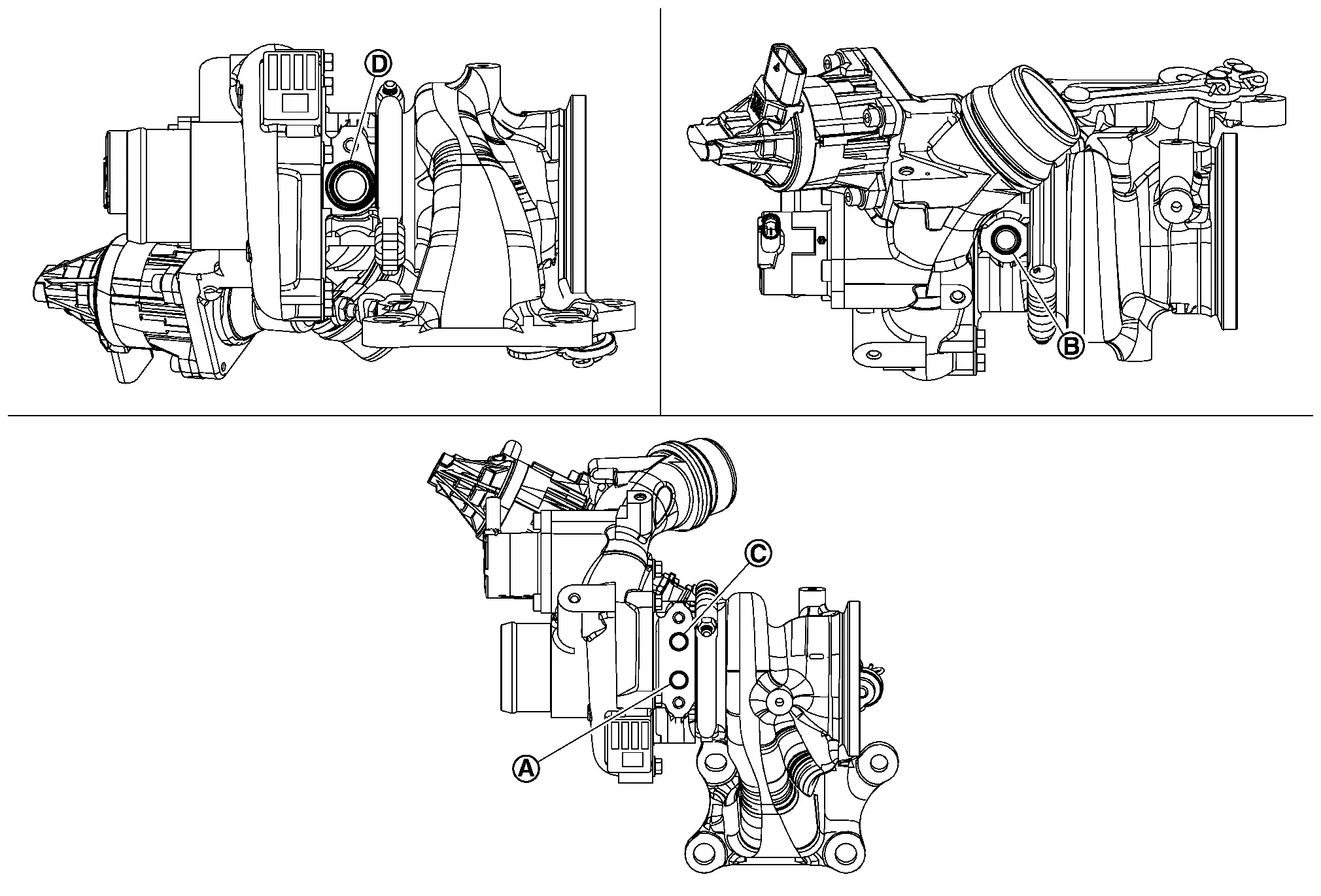
-
Use radiator cleaner to clean the water feed
 and return
  ports.
-
-
After cleaning, air-blow using an air gun.
-
Air-blow the compressor wheel, turbine wheel, compressor housing, and turbine housing.
Turbine Wheel and Compressor Wheel
-
Check visually, and by other means, for adhering oil.
-
Check visually, and by other means, for adhering carbon.
-
Check for bent or broken vanes.
-
Check for interference with the housing.
Rotor Shaft
-
Rotate rotor shaft
by hand and check that it turns smoothly without resistance or sticking.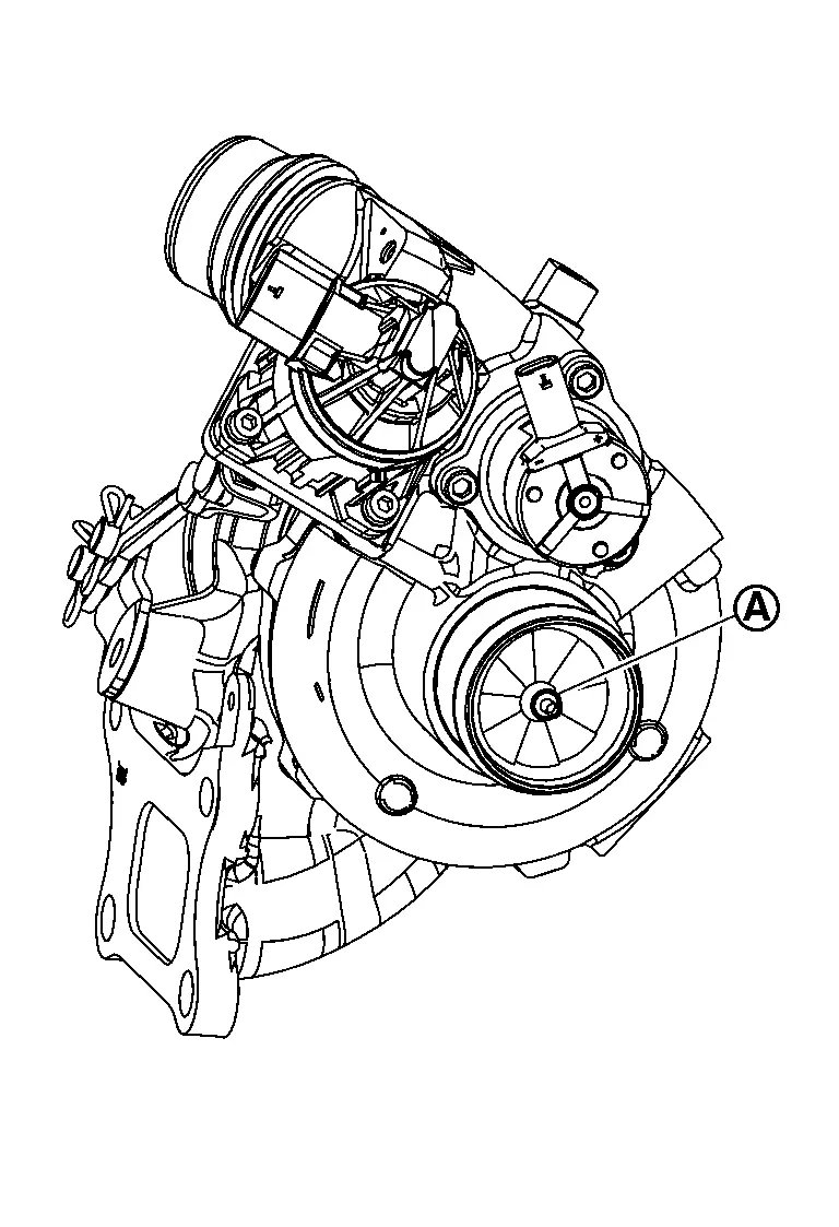
-
Shake rotor shaft vertically and horizontally and check for looseness.
Surface Distortion
-
Using suitable tool (A) and suitable tool (B), check the surface distortion of turbocharger mating surface.
Limit : Turbocharger -
If it exceeds the limit, replace turbocharger.
INSPECTION AFTER INSTALLATION
Start the engine and increase the engine speed. Check for engine oil leaks, exhaust gas leaks and engine coolant leaks.
|
Location to check for air leaks | |
Location to check for engine oil leaks | |
Location to check for engine coolant leaks |
|
Location to check for exhaust gas leaks |
Other materials:
Dtc/circuit Diagnosis. B2906-11 Recliner Sensor
DTC Description
DTC DETECTION LOGIC DTC No.
CONSULT screen items
(Trouble diagnosis content) DTC detection condition
B2906-11
Recliner Sensor
Diagnosis condition
The Recliner Sensor signal is shorted to ground
Signal (terminal)
Reclining Motor (terminal #5)
Threshold
...
System Description. System (back Door Opener System)
System Description
SYSTEM DIAGRAM Component Function
Back door opener switch
Refer to Back Door Opener Switch.
Back door opener actuator
Refer to Back Door Lock Assembly.
ABS actuator and electric unit (control unit)
Transmit Nissan Ariya vehicle speed signal to BCM via CAN c ...
Component Parts
Brake Control System
Component Parts Location
A.
Engine Room (LH Side)
No. Component Function
1.
Steering angle sensor
Refer to Steering Angle Sensor.
2.
Combination Meter
Refer to Component Parts Location (Type A Meter) or Component Parts Location (Type B Meter) f ...