Nissan Rogue (T33) 2021-Present Service Manual: High Pressure Fuel Pump and Fuel Hose
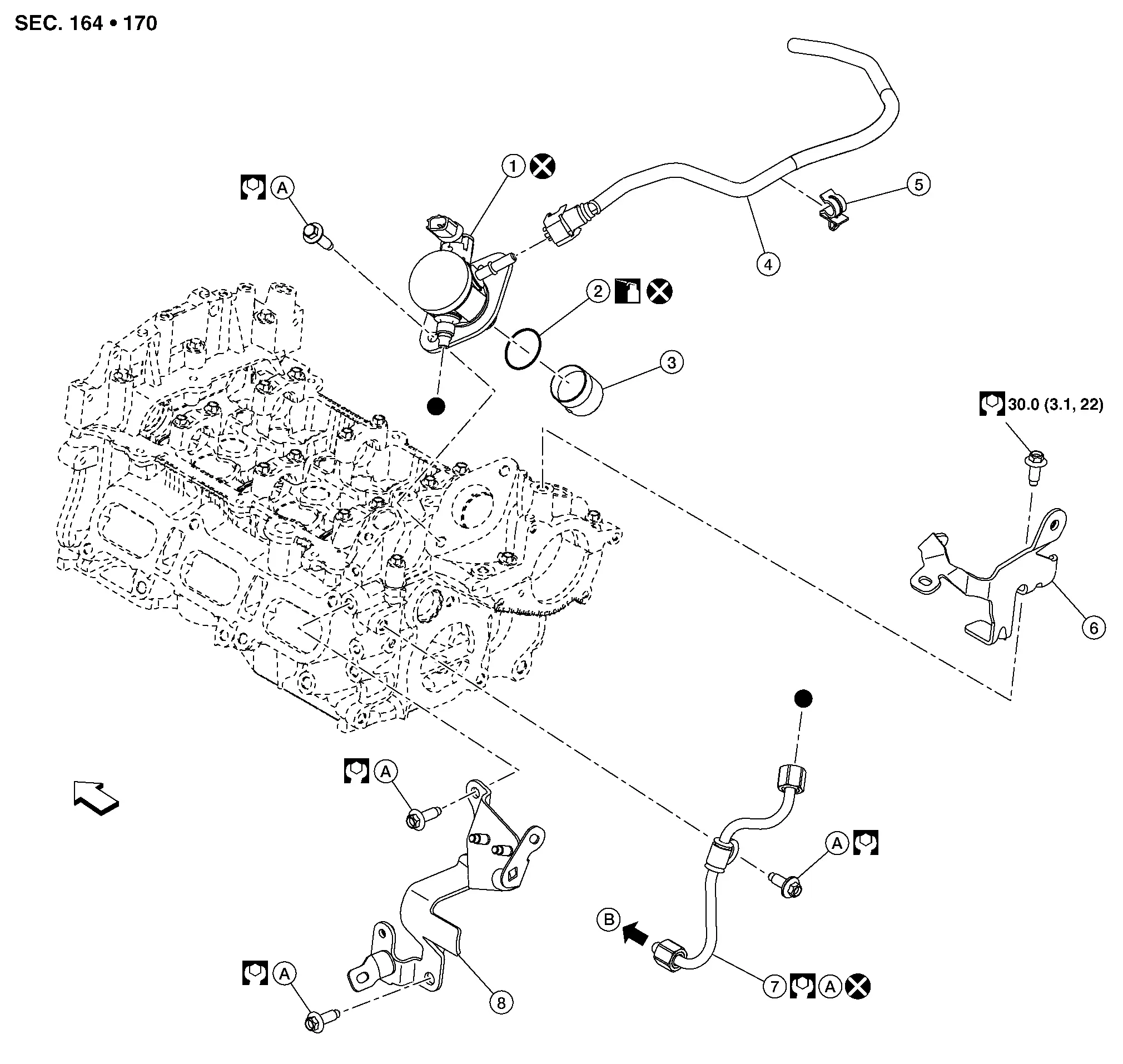
Exploded View
CAUTION:
Never remove or disassemble parts unless instructed as shown in the figure.
 |
High pressure fuel pump |  |
O-ring |  |
High pressure fuel pump lifter |
 |
Fuel hose |  |
Clip |  |
Bracket 1 |
 |
High pressure fuel tube |  |
Bracket 2 | ||
 |
Comply with the installation procedure when tightening. Refer to Removal and Installation. |  |
To high pressure fuel rail. Refer to Exploded View. | ||
| : Engine front. | |||||
 |
: N·m (kg-m, ft-lb) | ||||
 |
: Should be lubricated with oil. | ||||
 |
: Always replace after every disassembly. | ||||
 |
: Indicates that the parts are connected at points with same symbols in actual Nissan Ariya vehicle. | ||||
Removal and Installation
REMOVAL
WARNING:
-
Be sure to read Precaution for Handling High Pressure Fuel System when working on the high pressure fuel system.
-
Put a “CAUTION: FLAMMABLE” sign in the workshop.
-
Be sure to work in a well ventilated area and furnish workshop with a CO2 fire extinguisher.
-
Never smoke while servicing fuel system. Keep open flames and sparks away from the work area.
-
To avoid the danger of being scalded, never drain engine coolant when engine is hot.
Release fuel pressure. Refer to Work Procedure.
Remove engine cover. Refer to Removal and Installation. (With engine cover models)
Remove air cleaner assembly. Refer to Removal and Installation.
Remove intake manifold. Refer to Removal and Installation.
Remove purge pump assembly. Refer to Removal and Installation.
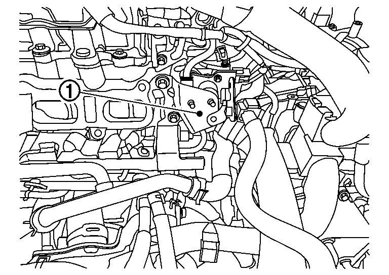
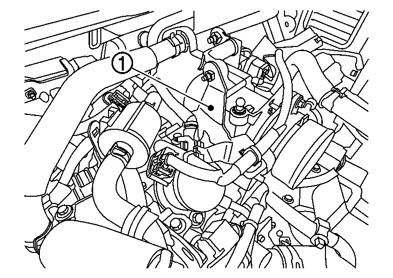
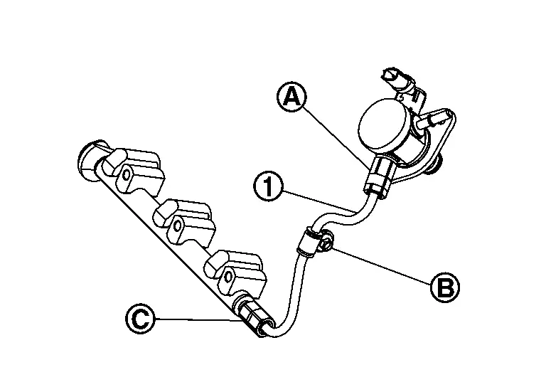
Remove bracket 2 (1).
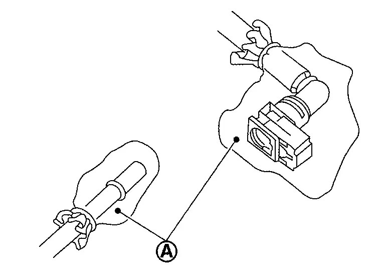
Disconnect quick connector (A) with the following procedure.Disconnect fuel feed hose (2) from bracket hose clamp (1).
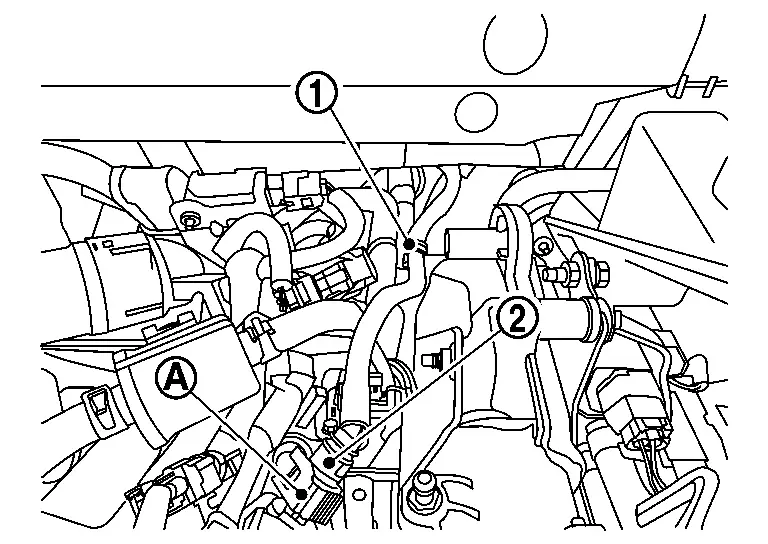
 NOTE:
NOTE:
If the fuel feed hose is stuck, hold the fuel pipe by hand and disconnect it by pushing and pulling.
CAUTION:
-
Keep parts away from heat source. Especially, be careful when welding is performed around them.
-
Never expose parts to battery electrolyte or other acids.
-
Never bend or twist connection between quick connector and fuel feed hose during installation/removal.
-
Pull quick connector holding .
-
Never remove the retainer.
-
Prepare a tray and waste beforehand as fuel leaks out.
-
Never pull with lateral force applied. O-ring inside quick connector may be damaged.
-
To prevent damage to each joint and protect it from the entry of foreign matter, cover the joint with plastic bag (A) or an equivalent.
Disconnect high pressure fuel pump harness connector.
Remove bracket 1 (1).
Remove multi way control valve.
Remove high pressure fuel tube.
CAUTION:
Do not reuse high pressure fuel tube.
Disconnect high pressure fuel pump harness connector from the high pressure fuel pump.
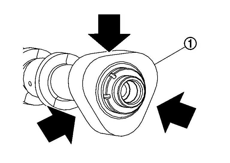
Remove high pressure fuel pump (1) and lifter.
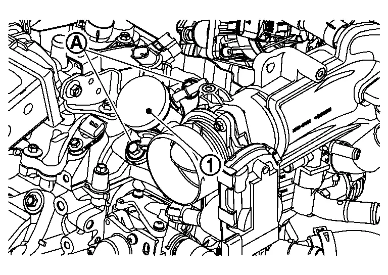
CAUTION:
-
To prevent damage to high pressure fuel pump and camshaft bracket, loosen bolt (A) alternately by one turn at a time until the reaction force applied on the high pressure fuel pump disappears.
-
Do not reuse O-rings.
INSTALLATION
CAUTION:
-
Do not reuse O-rings.
-
To prevent damage to parts due to generated abnormal stress and eccentric load, always observe the installation procedure.
Install high pressure fuel pump according to the following procedure.Check the orientation of pump cam from the mounting area (view arrow) of high pressure fuel pump.
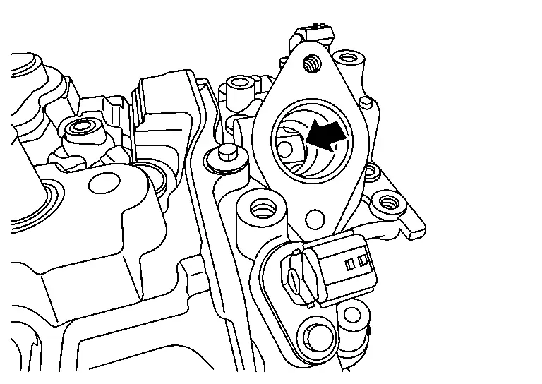
|
: Camshaft (EXH) |
NOTE:
For BDC area, anywhere within the area indicated by arrow can be accepted.
Install O-ring to high pressure fuel pump. When handing new O-ring, paying attention to the following caution items:CAUTION:
-
Do not reuse O-ring.
-
Handle O-ring with bare hands. Never wear gloves.
-
Lubricate O-ring with new engine oil.
-
Never clean O-ring with solvent.
-
Check that O-ring and its mating part are free of foreign material.
-
Never damage O-ring with tools and fingernails during the installation. In addition, twisting or stretching O-ring is not allowed. If O-ring is stretched during the installation to high pressure fuel pump, never install high pressure fuel pump immediately.
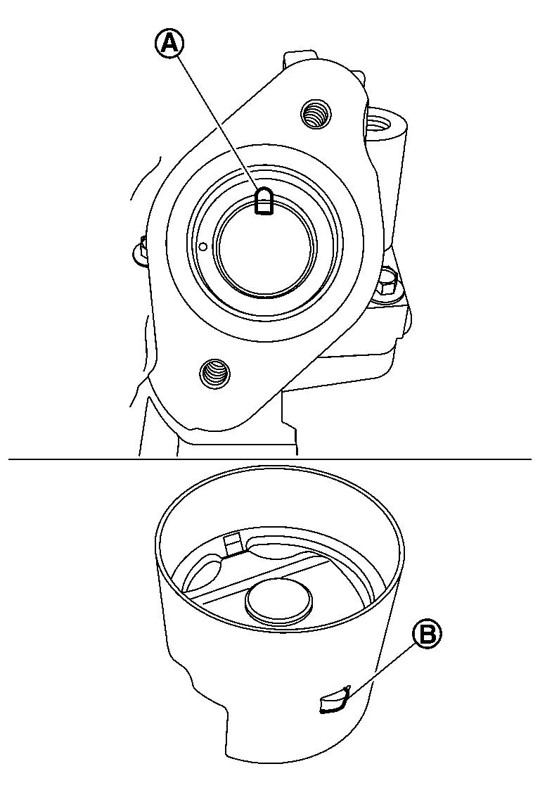
NOTE:
When installing high pressure fuel pump lifter, note the orientation of protrusion (B) and cutout (A) in camshaft bracket, they should be aligned.
Apply oil to the fitting area of high pressure fuel pump O-ring and camshaft bracket side to install high pressure fuel pump. Install high pressure fuel pump. To prevent damage to high pressure fuel pump and camshaft bracket, the following instructions must be observed.-
Tighten the high pressure fuel pump bolt (A) until it hits the high pressure fuel pump (1).
-
Tighten bolts (A) by alternating sides one turn at a time until high pressure fuel pump (1) in to camshaft bracket.
-
Tighten high pressure fuel pump bolts to the specified torque.
high pressure fuel pump bolts : 30.0 N·m (3.1 kg-m, 22ft-lb)
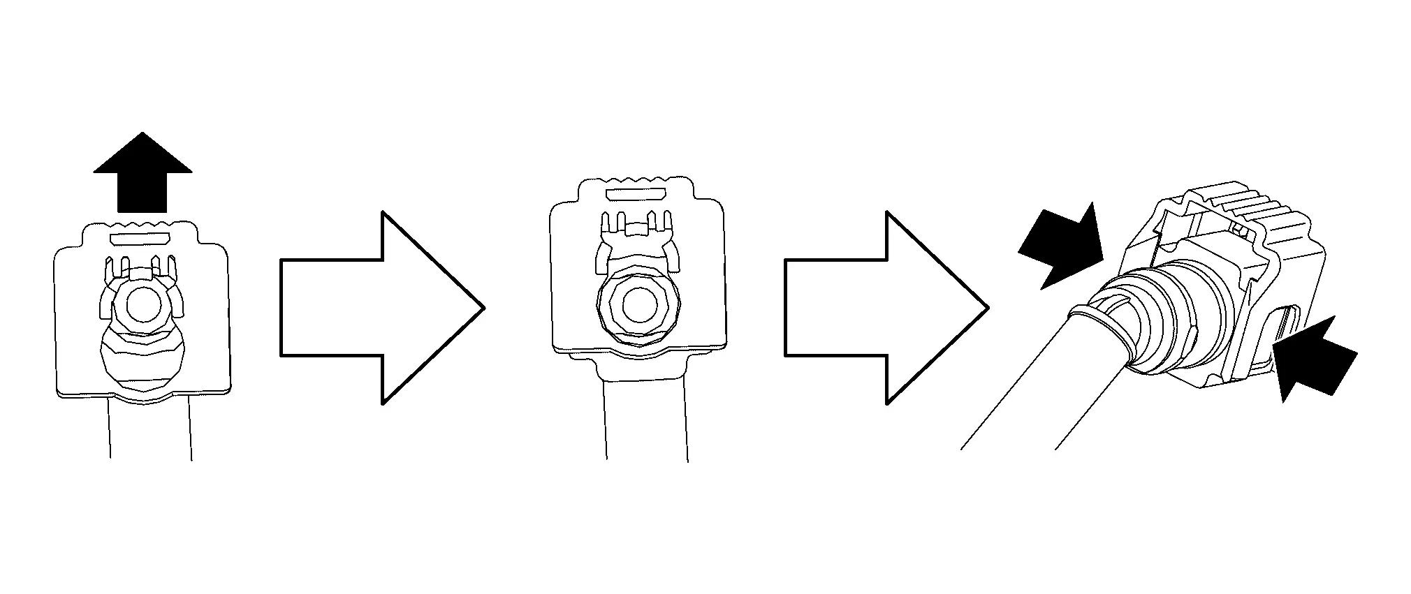
Connect fuel feed hose with the following procedure, and them install the fuel feed hose.Check no foreign substances are deposited in and around matching pipe and quick connector, and no damage on them. Quick connector shall be inserted gradually, aligning with the axis of the matching pipe. Insert the retainer until it clicks and check the retainer is locked. After insertion, pull the connector and check that the connector is locked.
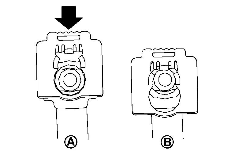
| A | : Unlock position |
| B | : Lock position |
CAUTION:
If retainer cannot be installed smoothly, quick connector may be have not been installed correctly. Check connection again.
Install the fuel tube with the following procedure.
CAUTION:
-
When removing high pressure fuel tube, always replace high pressure fuel pump and high pressure fuel rail together with high pressure fuel tube.
-
Never reuse high pressure fuel tube, high pressure fuel pump and high pressure fuel rail.
CAUTION:
When temporarily tightening flare nut, place pipe in the center of the nut inner diameter.
Temporarily tighten the high pressure fuel tube bracket mounting bolt (B). Tighten flare nut (A) to the specified torque. |
: 10 N·m (1.0 kg-m, 89 in-lb) |
CAUTION:
Before tightening, check that the tool is attached at a 90° angle to the flare nut when working.
Tighten flare nut (C) to the specified torque. |
: 10 N·m (1.0 kg-m, 89 in-lb) |
CAUTION:
Before tightening, check that the tool is attached at a 90° angle to the flare nut when working.
Tighten the high pressure fuel tube bracket mounting bolt (B) specified torque. |
: 25.0 N·m (2.6 kg-m, 18 ft-lb) |
| Specified Angle | : 60° - 65° |
NOTE:
After performing angle tightening for high pressure fuel tube flare nuts, check the torque of the flare nuts. If the torque is less than 27 Nm (2.8 kg-m, 20 ft-lb) or more than 61 Nm (6.2 kg-m, 45 ft-lb), it is necessary to replace the high pressure fuel pump, high pressure fuel tube and high pressure fuel rail.
Again tighten flare nut (C) to the specified angle.| Specified Angle | : 60° - 65° |
NOTE:
After performing angle tightening for high pressure fuel tube flare nuts, check the torque of the flare nuts. If the torque is less than 27 Nm (2.8 kg-m, 20 ft-lb) or more than 61 Nm (6.2 kg-m, 45 ft-lb), it is necessary to replace the high pressure fuel pump, high pressure fuel tube and high pressure fuel rail.
Install in the reverse order of removal after this step.
CAUTION:
After checking fuel leakage, maintain ten minutes of idling to bleed the fuel line.
Inspection
INSPECTION AFTER INSTALLATION
Check for Fuel Leakage
Turn ignition switch “ON” (with the engine stopped). With fuel pressure applied to fuel piping, check that there is no fuel leakage at connection points.
NOTE:
Use mirrors for checking at points out of clear sight.
Start the engine. With engine speed increased, check again that there is no fuel leakage at connection points.
CAUTION:
Never touch the engine immediately after it is stopped because the engine is extremely hot.
Other materials:
Dtc/circuit Diagnosis. Rear Window Defogger Switch
Component Function Check
CHECK REAR WINDOW DEFOGGER SWITCH FUNCTION
Check that the indicator lamp of rear window defogger illuminates when rear window defogger switch ON.
Is the inspection result normal?
YES>>
Rear window defogger switch function is OK.
NO>>
Refer to Diagnosis P ...
Electric Shift Control Module
Exploded View
Electric shift control module
: N·m (kg-m, in-lb) : Vehicle front
Removal and Installation
REMOVALDisconnect the negative battery terminal. Refer to Exploded View.
Remove instrument side panel LH. Refer to Exploded View.
Disconnect the harn ...
Symptom Diagnosis. Ignition Position Warning Function Does Not Operate
Diagnosis Procedure
CHECK POWER DOOR LOCK OPERATION
Check door lock/unlock using door lock/unlock switch.
Does door lock/unlock with door lock/unlock switch?
YES>>
GO TO 2.
NO>>
Refer to Diagnosis Procedure.
CHECK DOOR SWITCH
Check front door switch (front LH).
Refer to Compo ...