Nissan Rogue (T33) 2021-Present Service Manual: Fuel Injector and Fuel Tube
Exploded View
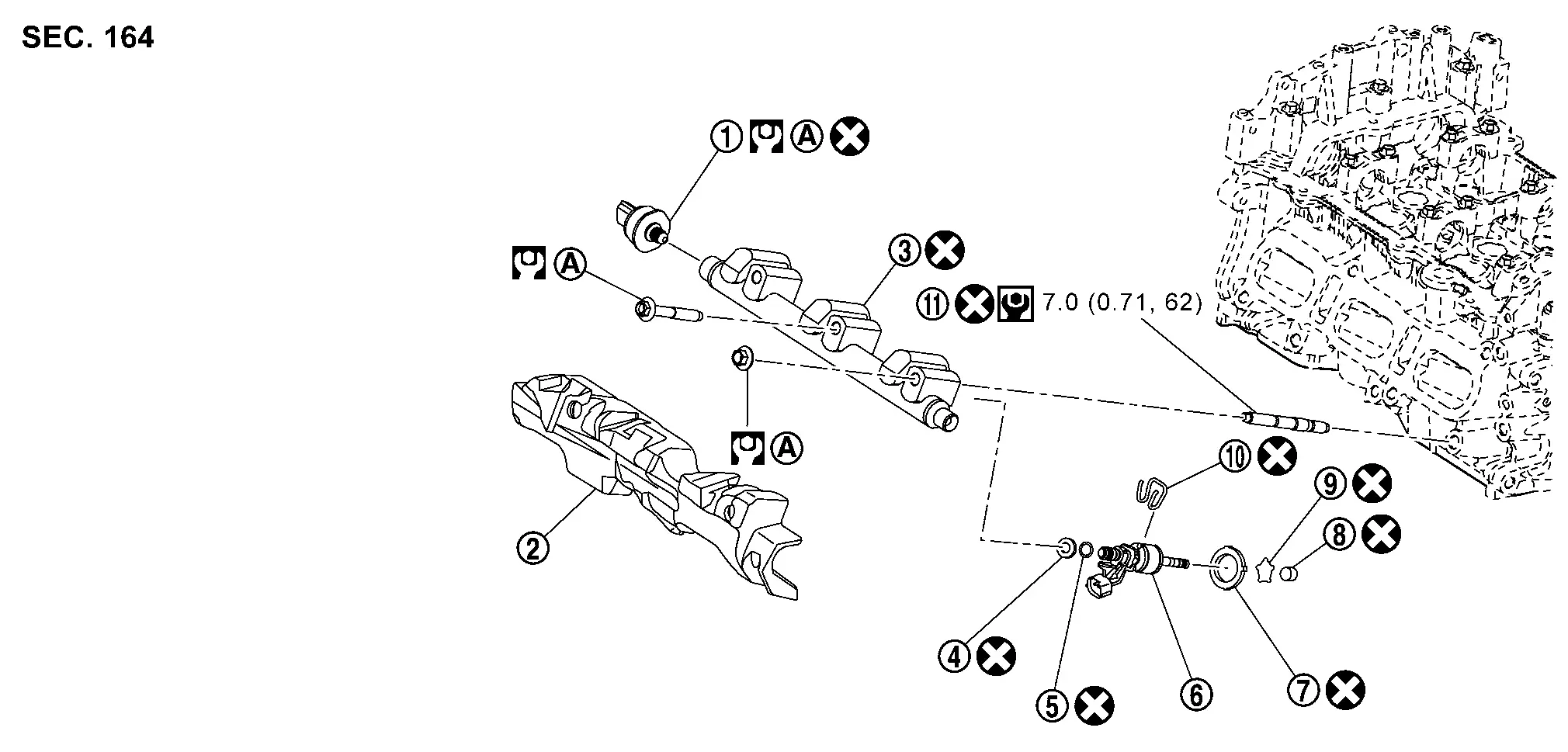
 |
Fuel rail pressure sensor |  |
High pressure fuel rail insulator |  |
High pressure fuel rail |
 |
O-ring (black) |  |
Support disc |  |
Fuel injector |
 |
Decoupling element |  |
Valve seat |  |
Retaining ring spring |
 |
Holding down appliance |  |
Stud bolt | ||
 |
Comply with the installation procedure when tightening. Refer to Removal and Installation. | ||||
 |
: N·m (kg-m, ft-lb) | ||||
 |
: N·m (kg-m, in-lb) | ||||
 |
: Always replace after every disassembly. | ||||
CAUTION:
Do not remove or disassemble parts unless instructed as shown.
Removal and Installation
WARNING:
-
Put a âCAUTION: FLAMMABLEâ sign in the workshop.
-
Be sure to work in a well ventilated area and furnish workshop with a CO2 fire extinguisher.
-
Never smoke while servicing fuel system. Keep open flames and sparks away from the work area.
REMOVAL
Release the fuel pressure. Refer to Work Procedure.
Drain engine coolant. Refer to Draining.
Disconnect the battery negative terminal. Refer to Removal and Installation.
Remove intake manifold. Refer to Removal and Installation.
Remove multi way control valve. Refer to Removal and Installation.
Remove high pressure fuel rail insulator.
Remove high pressure fuel tube. Refer to Removal and Installation.
Remove heater pipe. Refer to Removal and Installation.
Disconnect harness connector from fuel injector.
Remove the sub starter & generator and compressor bracket. Refer to Removal and Installation.
Disconnect harness connector from fuel rail pressure sensor.
Remove fuel rail pressure sensor if necessary.
Remove high pressure fuel rail and fuel injector assembly.
-
Loosen mounting bolts and nuts in the reverse order of as shown in the figure.
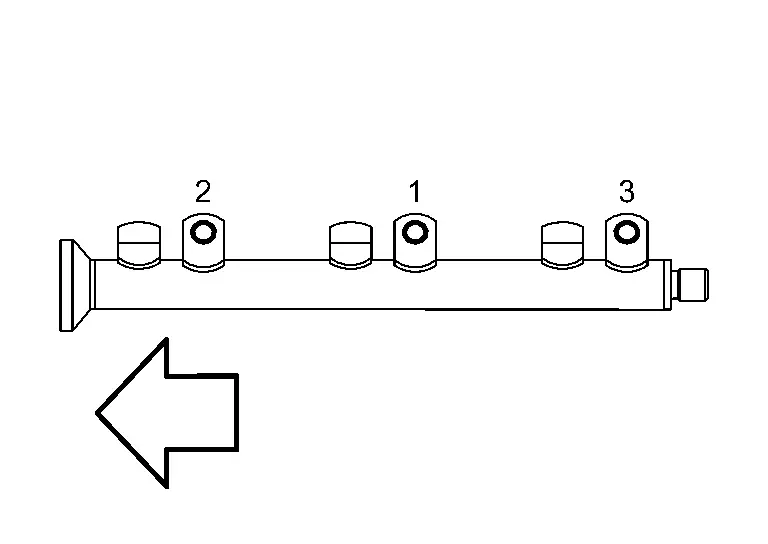

: Engine front
CAUTION:
-
When removing, be careful to avoid any interference with fuel injector.
-
Use a shop cloth to absorb any fuel leakage from high pressure fuel rail.
Remove fuel injector from cylinder head as per the following.
CAUTION:
-
Be careful with remaining fuel that may go out from fuel rail.
-
Be careful not to damage injector nozzles during removal.
-
Never bump or drop fuel injector.
-
Never disassemble fuel injector.
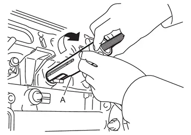
-
Remove injector holder.
-
Install Tool (A) to the injector connector side so that cutout
 of injector remover faces the injector connector side.
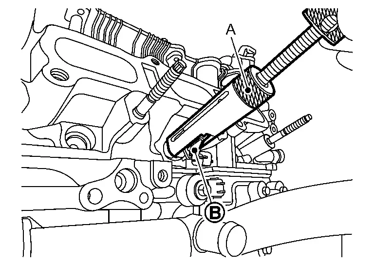
Tool : KV101296S0 (NI-53166) -
Hook pawl portion (B) of Tool (A) to groove portion (C) of injector.
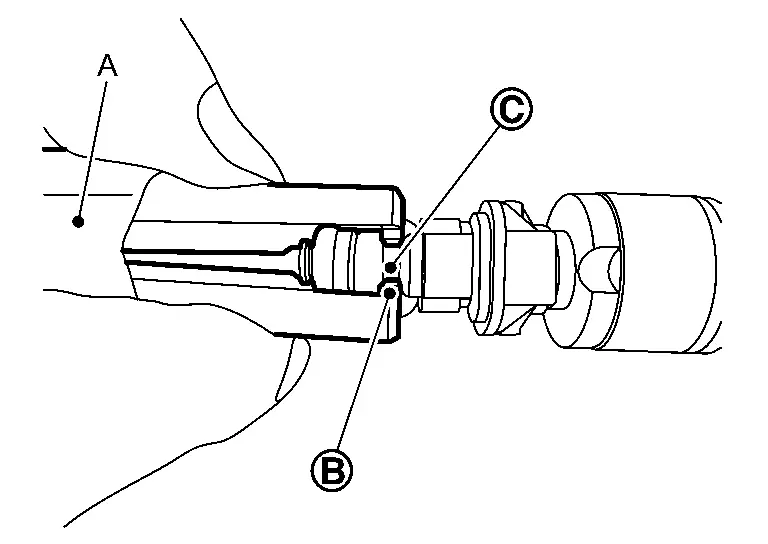
Tool : KV101296S0 (NI-53166) -
Press down body portion of Tool (A) until it contacts cylinder head.
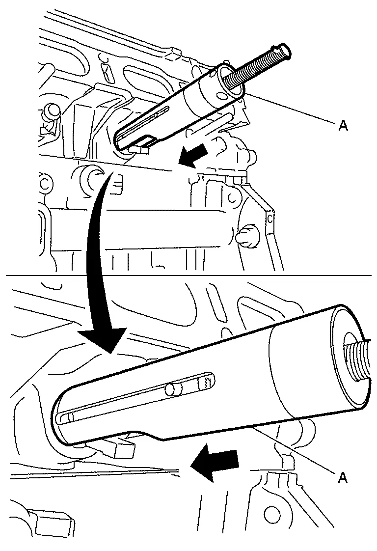
Tool : KV101296S0 (NI-53166) -
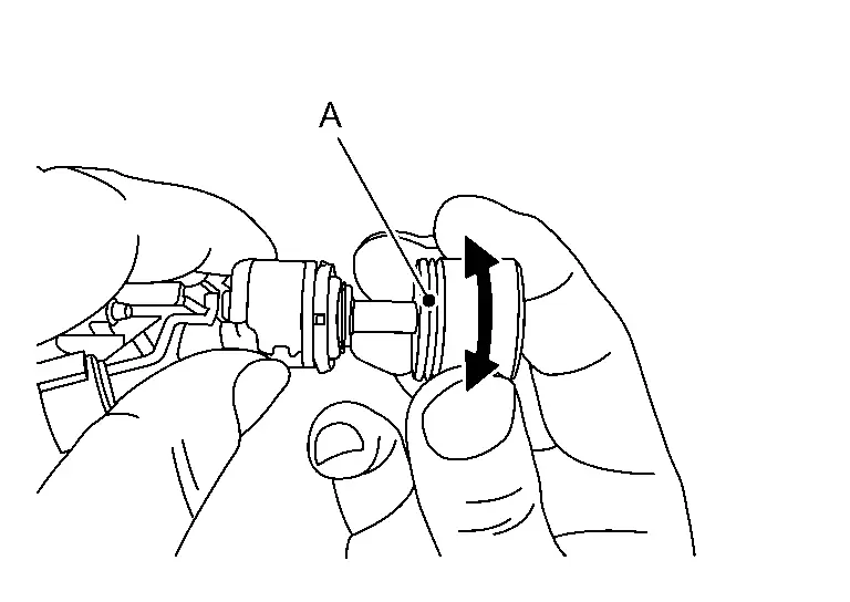
Tighten Tool clockwise and remove injector from cylinder head.
Tool : KV101296S0 (NI-53166) -
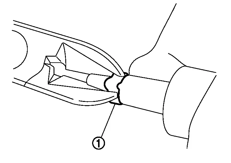
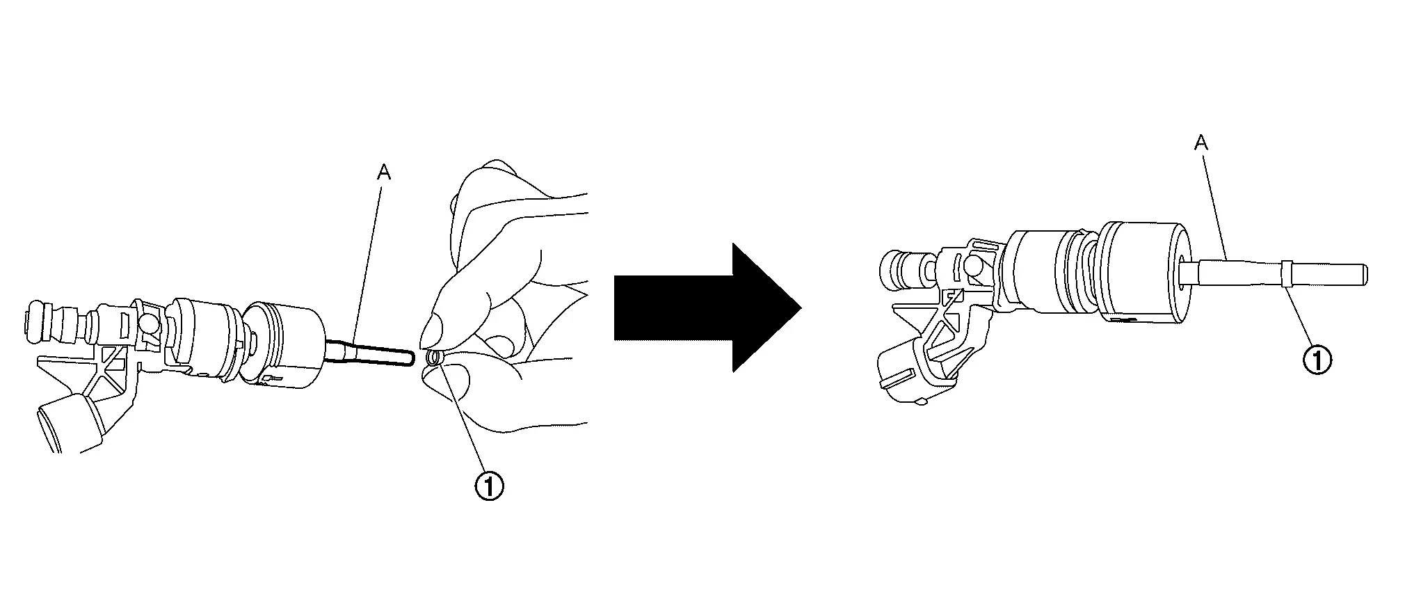
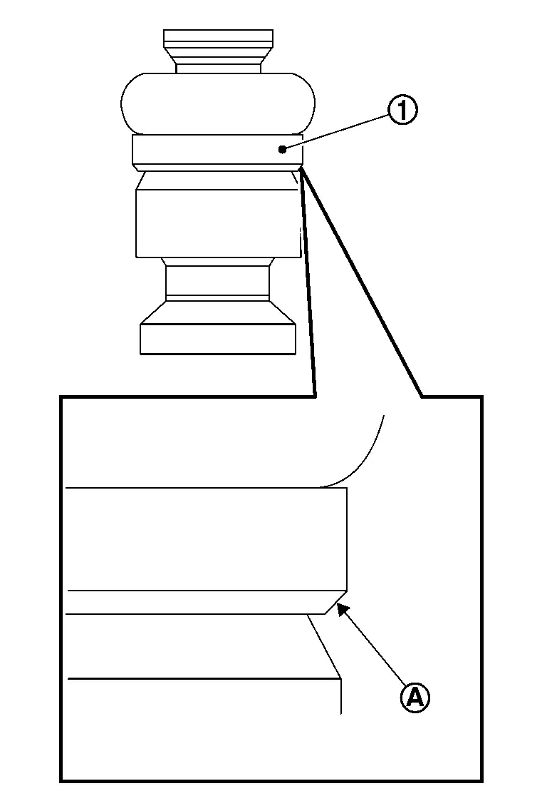
Cut seal ring (1) while pinching it. Be careful not to damage injector.
Remove the high pressure fuel rail stud bolt from the cylinder head if necessary.
INSTALLATION
If removed, replace the high pressure fuel rail stud bolt.
Install seal ring to fuel injector using the following procedure:
CAUTION:
-
Handle seal ring with bare hands. Do not wear gloves.
-
Do not apply engine oil to seal ring.
-
Do not clean seal ring with solvent.
-
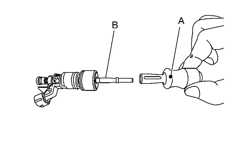
Point the injector mark (B) side of the Tool (A) in the direction of the fuel injector (1) and insert the injector seal drift in to the fuel injector.
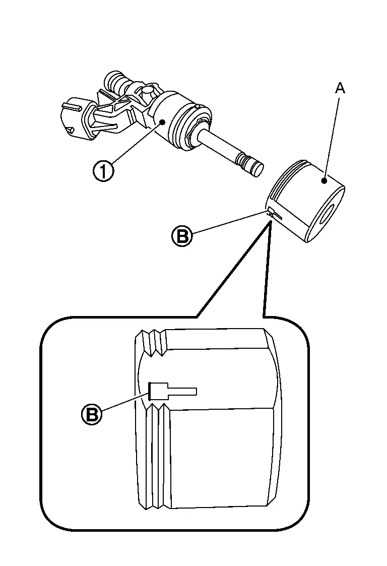
Tool : KV10119990 (NI-53151) -
Install Tool (A) to fuel injector (1).
Tool : KV10119990 (NI-53151) -
Set seal ring (1) into Tool (A).
Tool : KV10119990 (NI-53151) -
Set Tool (A) into Tool (B).
Tool : KV10119990 (NI-53151) -
Install seal ring (1) to the fuel injector by pushing it in, in the direction of the arrow with Tool (A)
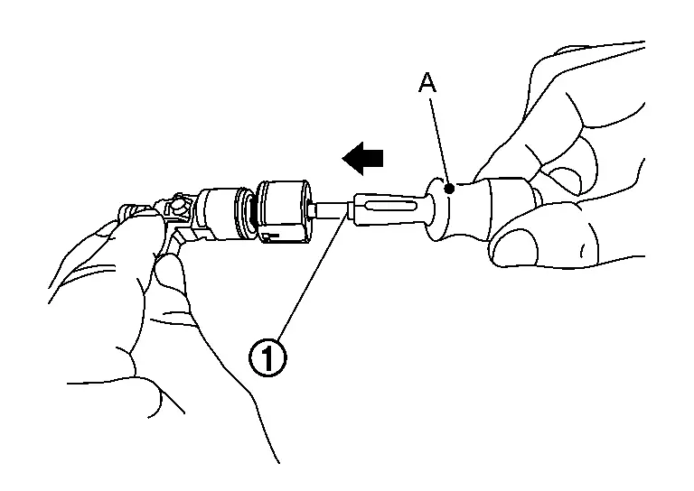
CAUTION:
Be careful that seal ring does not exceed the groove portion of fuel injector.
Tool : KV10119990 (NI-53151) -
Rotate clockwise and counterclockwise by 90° while pressing seal ring to fit it by Tool (A).
 NOTE:
NOTE:
This is done to correct any elongation of the seal ring caused by installation and for preventing sticking when inserting fuel injector into cylinder head.
Tool : KV10119990 (NI-53151)
Install O-ring and backup ring to fuel injector.
CAUTION:
-
Do not reuse O-ring.
-
Handle O-ring with bare hands. Do not wear gloves.
-
Lubricate O-ring with new engine oil.
-
Do not allow engine oil into fuel passage of fuel injector.
-
Do not clean O-ring with solvent.
-
Check that O-ring and its mating part are free of foreign material.
-
When installing O-ring , be careful not to scratch it with tool or fingernails. Also be careful not to twist or stretch O-ring. If O-ring was stretched while it was being attached, do not insert it quickly into high pressure fuel rail.
-
Insert new O-ring straight into fuel rail. Do not decenter or twist it.
-
Always install the backup ring (1) in the right direction as instructed.
Install fuel injector (1) to fuel rail (2) as per the following:
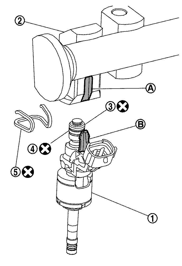
|
: O-ring (black) |
|
: Backup ring |
CAUTION:
-
Never reuse fuel injector holder. Replace it with a new one.
-
Be careful to keep fuel injector holder from interfering with O-ring. If interference occurs, replace O-ring.
-
Insert it while matching it to the axial center.
-
Insert so that protrusion (A) of fuel injector is aligned to cutout (B).
-
Check that protrusions of fuel injectors and fuel rail are aligned with cutouts of clips after installation.
Install fuel rail and fuel injector assembly to cylinder head.
-
Tighten mounting bolts and nuts in two steps in numerical order as shown in the figure.
: Engine front 1st step : 10.0 N·m (1.0 kg-m, 89 in-lb) 2nd step : 26.5 N·m (2.7 kg-m, 20 ft-lb)
Install the fuel rail pressure sensor if necessary using the following procedure:
CAUTION:
-
Do not reuse fuel rail pressure sensor.
-
Do not use fuel rail pressure sensor that has been dropped.
-
Check that high pressure fuel rail and fuel rail pressure sensor screw have no damage, foreign matter, or stains.
-
Do not use a tool on the fuel rail while tightening the fuel pressure sensor or fuel rail damage could result.
-
Do not scratch or crack high pressure fuel rail when installing fuel rail pressure sensor.
-
Apply engine oil to the threaded portion and front edge of the fuel rail pressure sensor.
-
Before tightening fuel rail pressure sensor, securely install a hexagon tool.
-
Lubricate fuel rail pressure sensor threads with clean engine oil.
CAUTION:
Check that high pressure fuel rail and fuel rail pressure sensor threads have no damage or foreign matter.
-
Tighten fuel rail pressure sensor to the specified torque.
Fuel rail pressure sensor : 10.0 N·m (1.0 kg-m, 89 in-lb) -
Tighten fuel rail pressure sensor to the specified angle using angle wrench [SST:KV10112100 (BT8653-A)].
CAUTION:
-
To check tightening angle, use Tool. Do not judge the angle by visual inspection.
-
The torque value for the angle tightening must be 60 N·m (6.1 kg-m, 44 ft-lb) or less.
-
If torque value reaches 60 N·m (6.1 kg-m, 44 ft-lb), then replace the fuel rail pressure sensor and high pressure fuel rail with a new one.
Tightening angle : 35°
-
Connect the fuel rail pressure sensor harness connector.
Connect the fuel injector harness connector.
Install fuel rail insulator.
CAUTION:
-
As covering part of fuel tube connector at the back end of common rail can easily move because of its shape, do not remove it before installation.
-
Install the insulator so that it is placed under lower side of intake manifold flange.
Install the high pressure fuel tube. Refer to Removal and Installation.
Install the high pressure fuel rail protector using the following procedure:
-
Hand tighten the bolts (A) in as shown in the figure (temporarily).
-
Tighten the bolts in order number of to shown in the figure (specified torque).
High pressure fuel rail protector bolts : 25.0 N·m (2.6 kg-m, 18 ft-lb)
Installation of the remaining components is in the reverse order of removal.
CAUTION:
If fuel injector replaced, perform "FUEL INJECTOR OFFSET LEARNING". Refer to Description.
Inspection
Check for Fuel Leaks
Turn ignition switch âONâ (with the engine stopped). With fuel pressure applied to fuel piping, check that there are no fuel leaks at connection points.
NOTE:
Use mirrors for checking at points out of clear sight.
Start the engine. With engine speed increased, check again that there are no fuel leaks at connection points.
CAUTION:
Do not touch the engine immediately after stopped, as the engine becomes extremely hot.
Other materials:
U0402 Can Communication
DTC Description
DTC DETECTION LOGIC DTC
CONSULT screen terms
(Trouble diagnosis content)
DTC detection condition
U0402
00
Invalid data (TCM)
(Invalid Data Received From TCM)
Diagnosis condition
Ignition switch ON
Signal (terminal)
â
Threshold
When ECM is ...
Entretien gÃĐnÃĐral
Informations de base
Lors de lâutilisation normale de votre Nissan Rogue, les opÃĐrations dâentretien gÃĐnÃĐral doivent Être rÃĐalisÃĐes rÃĐguliÃĻrement et avec rigueur, conformÃĐment aux instructions dÃĐcrites dans cette section. Toute apparition de bruits anormaux, de vibrations inhabituelle ...
Basic Inspection. Additional Service When Replacing Air Bag Diagnosis Sensor Unit
Description
After replaced air bag diagnosis sensor unit, it is necessary to
perform control unit configuration with CONSULT. For details, refer to
Work Procedure.
Work Procedure
REPLACE AIR BAG DIAGNOSIS SENSOR UNIT
Replace air bag diagnosis sensor unit. Refer to Removal and Installation.
...