Nissan Rogue (T33) 2021-Present Service Manual: Ignition Coil, Spark Plug and Rocker Cover
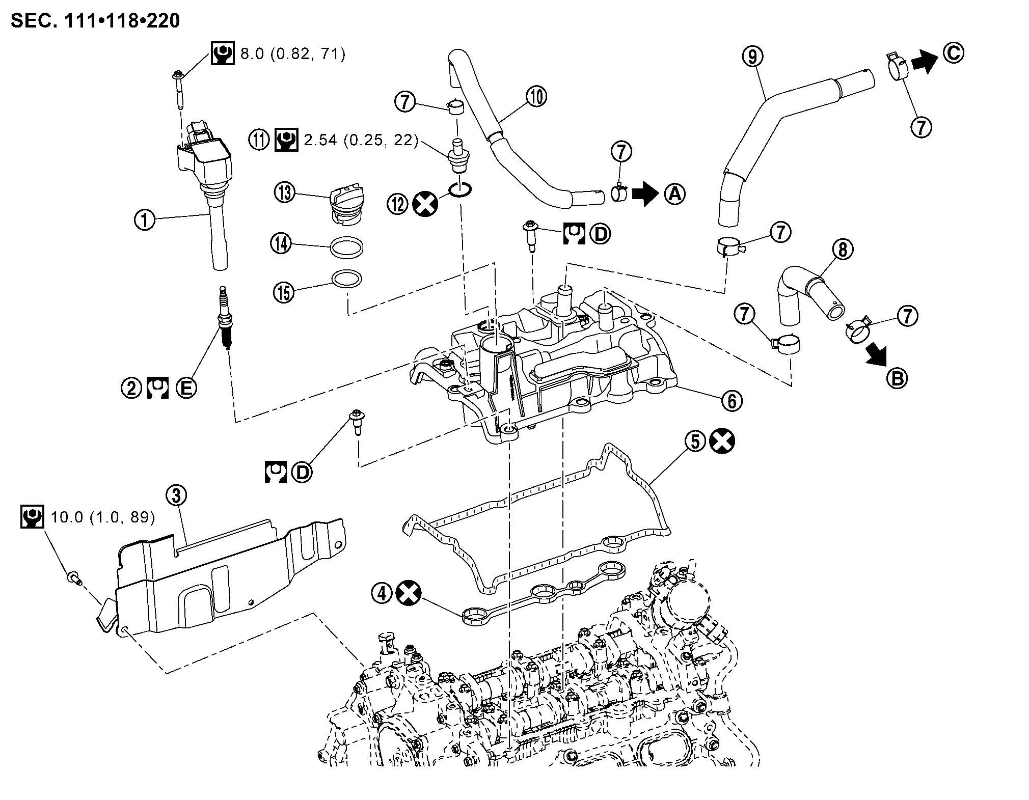
Exploded View
 |
Ignition coil |  |
Spark plug |  |
Cover (right) |
 |
Rocker cover gasket |  |
Rocker cover gasket |  |
Rocker cover |
 |
Clamp |  |
Resonator hose |  |
Turbo hose |
 |
Blow-by hose |  |
PCV valve |  |
O-ring |
 |
Oil filler cap |  |
Oil filler gasket 1 |  |
Oil filler gasket 2 |
 |
To Intake manifold. Refer to Exploded View. |  |
To Resonator. Refer to Exploded View. |  |
To Air duct. Refer to Exploded View. |
 |
Comply with the installation procedure when tightening. Refer to Removal and Installation. |  |
Comply with the installation procedure when tightening. Refer to Removal and Installation. | ||
 |
: N·m (kg-m, ft-lb) | ||||
 |
: N·m (kg-m, in-lb) | ||||
 |
: Always replace after every disassembly. | ||||
Removal and Installation
REMOVAL
Removal charge air cooler. Refer to Removal and Installation.
Disconnect the harness connectors from the ignition coils.
Remove the ignition coils.
Disconnect the harness clip from the rocker cover and reposition harness.
Remove the PCV hose and blow-by hose from the rocker cover.
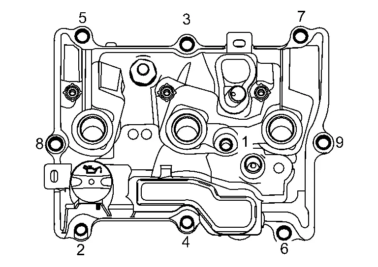
Loosen the rocker cover bolts in reverse of the sequence shown.
Remove the rocker cover and rocker cover gasket.
CAUTION:
-
Do not reuse rocker cover gasket.
-
Do not drop or shock rocker cover.
-
Discard any rocker cover which has been dropped or shocked.
Remove the oil filler cap if necessary.
Remove the PCV valve if necessary.
CAUTION:
Do not reuse O-ring.
INSTALLATION
Apply liquid gasket to the positions shown.
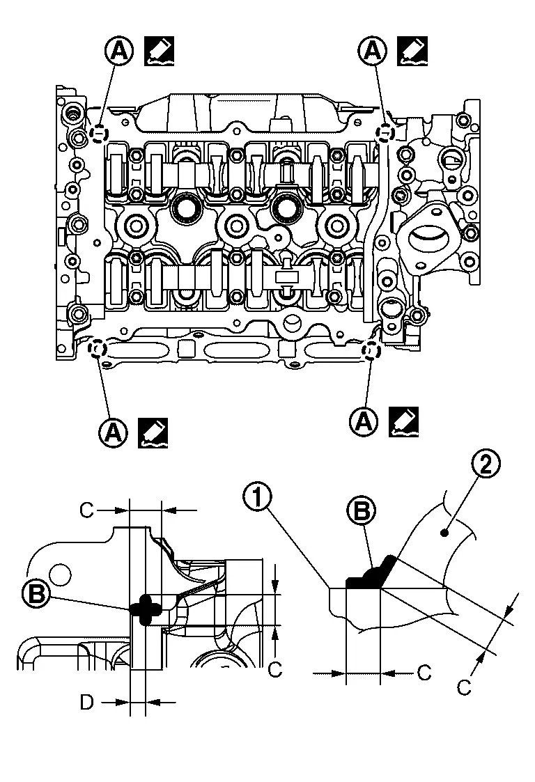
-
Use Genuine RTV Silicone Sealant or an equivalent. Refer to Recommended Chemical Products and Sealants.
|
: Cylinder head |
|
: Camshaft bracket |
| C | : 10 mm (0.39 in) |
| D | : 4 mm (0.16 in) (Application position of liquid gasket from the end surface of the camshaft bracket) |
Install rocker cover gasket to rocker cover.
CAUTION:
-
Do not reuse rocker cover gasket.
-
Do not drop or shock rocker cover.
-
Discard any rocker cover which has been dropped or shocked.
 NOTE:
NOTE:
Make sure rocker cover gasket is securely installed in the groove in the rocker cover.
Install the rocker cover and tighten the bolts to the specified torque in the sequence shown.
| Step 1 |
: 1.96 N·m (0.20 kg-m, 17 in-lb) |
| Step 2 |
: 8.33 N·m (0.85 kg-m, 74 in-lb) |
Install the cover (right) and tighten the bolts to the specified torque in the sequence shown.
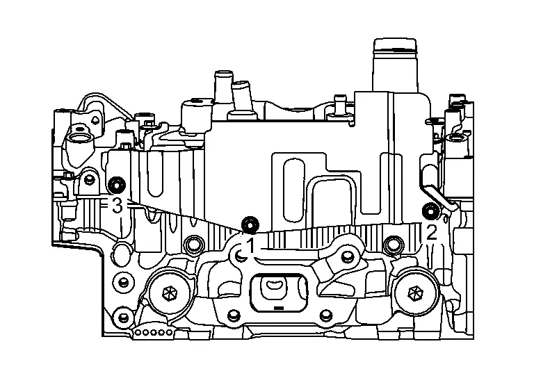
| Cover (right) bolts |
: 10.0 N·m (1.0 kg-m, 89 in-lb) |
Installation of the remaining components is in the reverse order of removal.
Other materials:
Fonctionnement du système
Capteurs sonar centraux
Capteurs sonar d’angle
Capteurs sonar latéraux (si le véhicule en est équipé)
Le système informe le conducteur par des alertes visuelles et sonores de la présence :
D’obstacles situés à l’avant lorsque le levier de vitesses est en position D (c ...
Basic Inspection. Calibration of Automatic Back Door Position Information
Description
When the following work is performed, it is necessary to perform
initial setting of automatic back door position information to operate
automatic back door system. Refer to Work Procedure.
After removing and installing, or replacing automatic back door control unit
After rem ...
Component Parts
Automatic Air Conditioning System
Component Parts Location
A.
Instrument panel
B.
Left front of Nissan Ariya vehicle
C.
Right side of blower unit assembly
D.
Right side of heater and cooling unit assembly
E.
Left side of heater and cooling unit assembly
...