Nissan Rogue (T33) 2021-Present Service Manual: Component Parts
Automatic Air Conditioning System
Component Parts Location
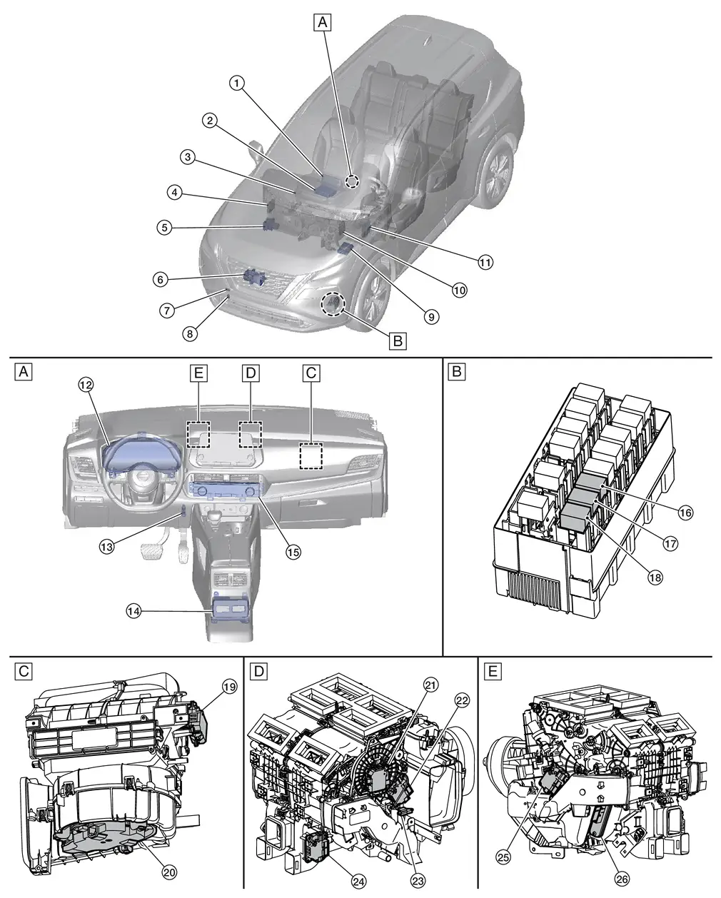
| A. | Instrument panel | B. | Left front of Nissan Ariya vehicle | C. | Right side of blower unit assembly |
| D. | Right side of heater and cooling unit assembly | E. | Left side of heater and cooling unit assembly |
| No. | Component | Function |
|---|---|---|
| 1. | AV control unit (with ProPILOT Assist 2.1) | Refer to Component Parts Location (with 12.3" color display) for detailed component location. |
| 2. | AV control unit (without ProPILOT Assist 2.1) | Refer to Component Parts Location (without ProPILOT Assist 2.1) for detailed component location. |
| 3. | Sunload sensor | Refer to Sunload Sensor. |
| 4. | A/C Amp. | Refer to A/C Amp.. |
| 5. |
ABS actuator and electric unit (control unit) [Anti-lock Braking System actuator and electric unit (control unit)] |
Transmits Nissan Ariya vehicle speed signal to A/C Amp. via CAN communication line. Refer to Component Parts Location for detailed component location. |
| 6. | A/C compressor | Refer to A/C Compressor. |
| 7. | Refrigerant pressure sensor | Refer to Refrigerant Pressure Sensor. |
| 8. | Ambient sensor | Refer to Ambient Sensor. |
| 9. | IPDM E/R |
Transmits/receives A/C compressor request and feedback signals between A/C Amp. and ECM via CAN communication line. Refer to Component Parts Location for detailed component location. |
| 10. | ECM (Engine Control Module) |
Receives A/C ON signal and blower fan ON signal from A/C amp., transmits A/C compressor request signal to IPDM E/R via CAN communication line. Refer to Component Parts Location for detailed component location. |
| 11. | BCM (Body Control Module) | Refer to Component Parts Location for detailed component location. |
| 12. | Combination meter |
Transmits ambient temperature signal to A/C amp. via CAN communication line. Refer to Component Parts Location (type A meter) or Component Parts Location (type B meter) for detailed component location. |
| 13. | In-Nissan Ariya vehicle sensor | Refer to In-vehicle Sensor for detailed component location. |
| 14. | Rear air control1 | Refer to Rear Air Control. |
| 15. | A/C switch assembly2 | Refer to A/C Switch Assembly. |
| 16. | PTC heater relay 1 | The PTC relays control the flow of current to the PTC heater. The PTC relays are controlled by the BCM. |
| 17. | PTC heater relay 2 | |
| 18. | PTC heater relay 3 | |
| 19. | Intake door motor | Refer to Intake Door Motor. |
| 20. | Front blower motor | Refer to Front Blower Motor. |
| 21. | Mode door motor | Refer to Mode Door Motor. |
| 22. | Air mix door motor RH | Refer to Air Mix Door Motor RH. |
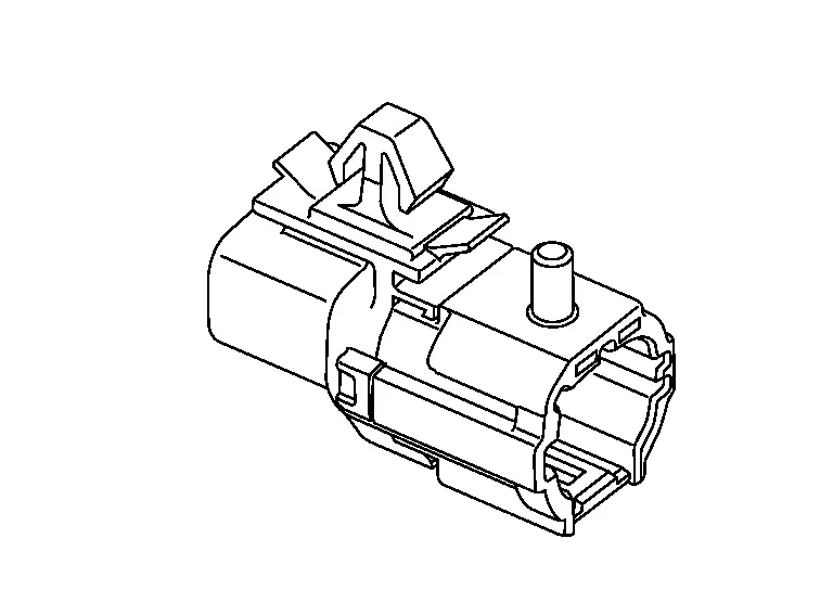
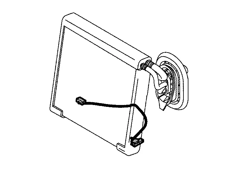
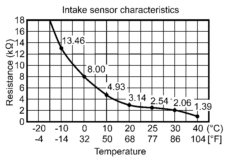
| 23. | Intake sensor | Refer to Intake Sensor. |
| 24. | Air mix door motor (rear)1 | Refer to Air Mix Door Motor (Rear). |
| 25. | Air mix door motor LH | Refer to Air Mix Door Motor LH. |
| 26. | PTC heater | Refer to PTC Heater. |
1: With rear air control
2: Without rear air control shown, with rear air control similar
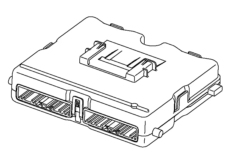
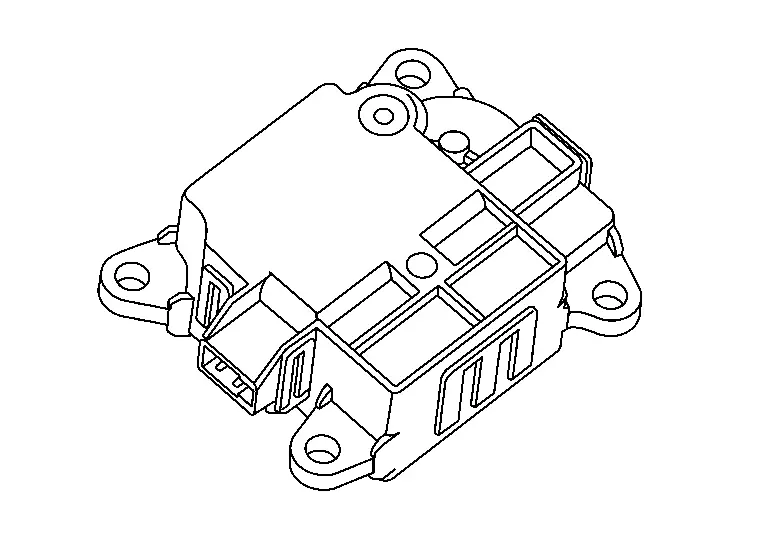
A/C Amp.
-
The A/C amp. is installed to the blower unit assembly. Refer to Component Parts Location.
-
A/C amp. controls the automatic air conditioning system by inputting and calculating signals from each sensor and each switch.
-
The A/C amp. consists of a microcomputer and input/output connectors for signals and power supply.
-
It has a CAN communications function, and it transmits and receives the necessary signals from each control module via CAN communication.
-
It has a LIN communications function, and transmits and receives signals to/from the A/C switch assembly, each door motor, rear air control and each seat heater.
-
A/C amp. has self-diagnosis function. Diagnosis of automatic air conditioning system can be performed quickly.
COMPONENT OPERATION
Refer to System Description.
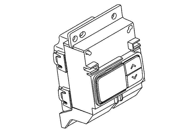
A/C Switch Assembly
-
The A/C switch assembly is installed to the center ventilator finisher. Refer to Component Parts Location.
-
A/C switch assembly transmits setting status to A/C amp. via LIN communication line. A/C amp. controls automatic air conditioning system.
-
A/C switch assembly has switches and display that can set and indicate the operation of automatic air conditioning system.
With rear air control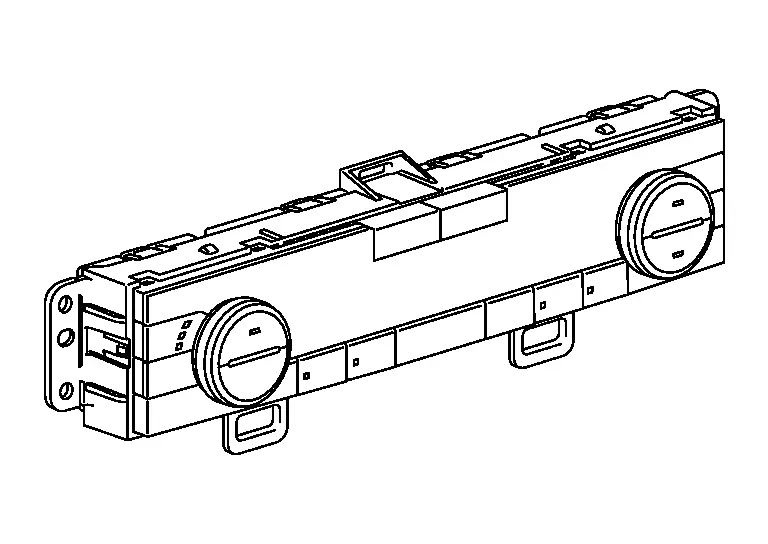
Without rear air control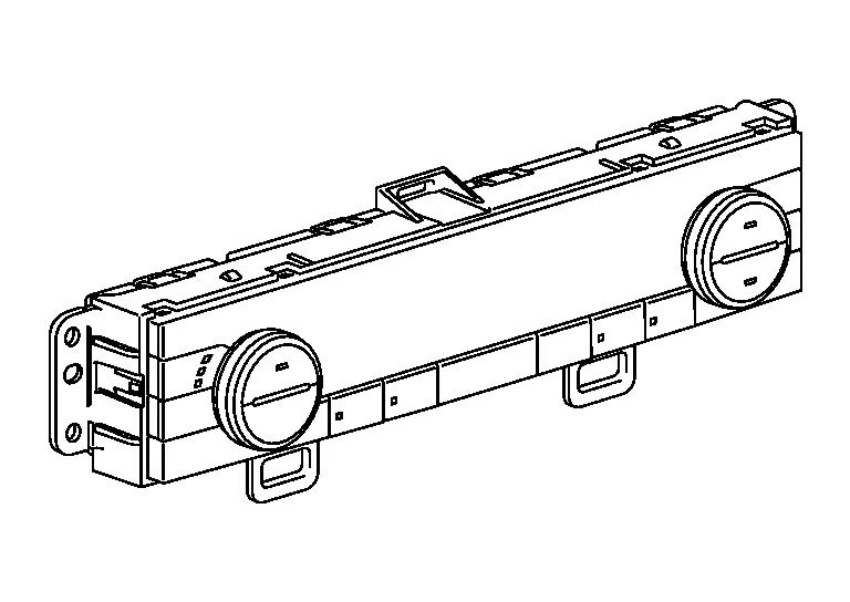
-
The conditions that are set for the automatic air conditioning system that is operated by each control switch are transmitted to the A/C amp. via LIN communication.
-
The operating status of the automatic air conditioner is transmitted from the A/C amp. via LIN communication.
COMPONENT OPERATION
-
The operation status of each switch is detected by the A/C switch assembly and is transmitted as an operation signal to the A/C amp. via LIN communication.
-
The following switch specification control was adopted:
-
Temperature control : Dial type
-
Air outlet control : Push-return type
-
Air inlet control : Push-return type
-
Air flow control : Push-return type
-
A/C compressor ON/OFF : Push-return type
 NOTE:
NOTE:
Regarding the push switches : Refer to the following for the differences between push-lock types and push-return types.
Operation Push-lock type Push-return type Switch ON operation 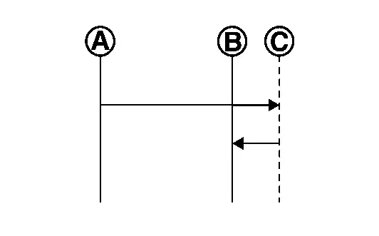
Switch OFF operation 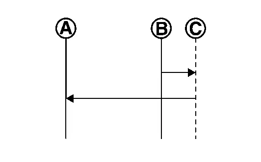
Push-lock type
-
Switch ON operation: At the time of switch ON operation, the switch is pushed from the reference point
 to the pushed position
  , and the switch turns ON. When the switch is released from this position, the switch returns from the pushed position to the hold position
  , and the switch position is held there.
 -
Switch OFF operation: At the time of the switch OFF operation, the switch is pushed from the hold position
to the pushed position . When the switch is released from this position, the switch returns from the pushed position to the reference point , and the switch turns OFF.
Push-return type
-
Switch ON operation: At the time of the switch ON operation, the switch is pushed from the reference point
to the pushed position , and the switch turns ON. When the switch is released from this position, the switch returns from the pushed position to the reference point . -
Switch OFF operation: At the time of the switch OFF operation, the switch is pushed from the reference point
to the pushed position , and the switch turns OFF. When the switch is released from this position, the switch returns from the pushed position to the reference point .
-
-
-
For details the function of each switch. Refer to Switch Name and Function.
Rear Air Control
-
The rear air control is installed to the console rear finisher. Refer to Component Parts Location.
-
The rear air control is activated by LIN communication with the A/C amp., and can set the rear temperature.
-
The rear air conditioning operating status is indicated on the display located on the control.
-
The conditions that are set for the rear air control that is operated by temperature switch are transmitted to the A/C amp. via LIN communication.
-
The operating status of the air conditioner is transmitted from the A/C amp. via LIN communication.
COMPONENT OPERATION
-
The operation status of each switch is detected by the rear air control and is transmitted as an operation signal to the A/C amp. via LIN communication.
-
The following switch specification control was adopted:
-
Temperature control : Push-return type
NOTE:
Regarding the push switches : Refer to the following for the differences between push-lock types and push-return types.
Operation Push-lock type Push-return type Switch ON operation Switch OFF operation Push-lock type
-
Switch ON operation: At the time of switch ON operation, the switch is pushed from the reference point
to the pushed position , and the switch turns ON. When the switch is released from this position, the switch returns from the pushed position to the hold position , and the switch position is held there. -
Switch OFF operation: At the time of the switch OFF operation, the switch is pushed from the hold position
to the pushed position . When the switch is released from this position, the switch returns from the pushed position to the reference point , and the switch turns OFF.
Push-return type
-
Switch ON operation: At the time of the switch ON operation, the switch is pushed from the reference point
to the pushed position , and the switch turns ON. When the switch is released from this position, the switch returns from the pushed position to the reference point . -
Switch OFF operation: At the time of the switch OFF operation, the switch is pushed from the reference point
to the pushed position , and the switch turns OFF. When the switch is released from this position, the switch returns from the pushed position to the reference point .
-
-
For the name and function of each switch. Refer to Switch Name and Function.
Ambient Sensor
-
The ambient sensor is installed to the active grille shutter. It measures the ambient air temperature. Refer to Component Parts Location.
-
The ambient sensor detects the temperature of the ambient air, and transmits the ambient sensor signal to the combination meter.
-
This signal is transmitted from the combination meter to the A/C amp. via CAN communication and is used in air conditioning system.
COMPONENT OPERATION
The ambient sensor measures the ambient air temperature, and transmits the ambient sensor signal to the combination meter. This sensor uses a thermistor with electrical resistance that decreases as the temperature increases.

Intake Sensor
-
Intake sensor is located on the evaporator. It measures evaporator temperature (through air temperature). Refer to Component Parts Location.
-
The intake sensor converts the evaporator surface temperature detected with thermistor into a voltage signal, and the A/C amp receives this voltage signal.
-
The sensor uses a thermistor which is sensitive to the change in temperature. The electrical resistance of the thermistor decreases as temperature increases.
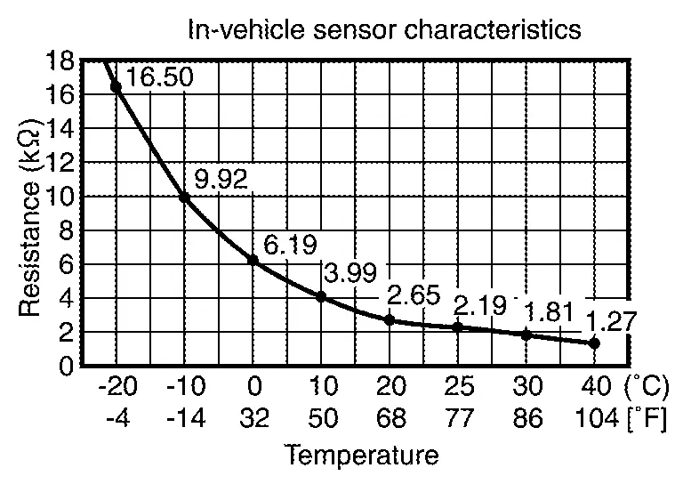
In-vehicle Sensor

-
The in-vehicle sensor is installed to the instrument lower panel center. Refer to Component Parts Location.
-
The in-Nissan Ariya vehicle sensor measures the temperature of the in-vehicle air taken in by the front blower motor.
-
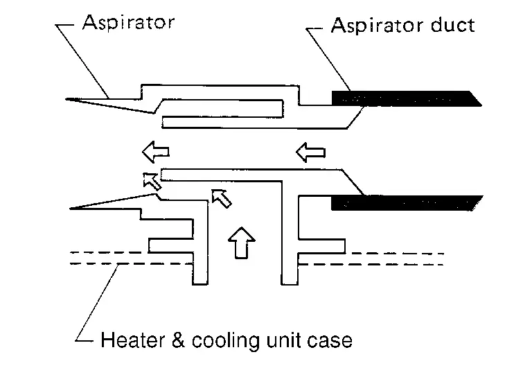
The in-Nissan Ariya vehicle sensor detects the temperature of the in-vehicle air that is taken in by the aspirator, and transmits the in-Nissan Ariya vehicle sensor signal to the A/C amp. This sensor uses a thermistor with electrical resistance that decreases as the temperature increases.
 NOTE:
NOTE:
The aspirator generates the vacuum by the air blown from the heater & cooling unit case and draws the air of the passenger room to the in-Nissan Ariya vehicle sensor area via the aspirator duct.
Refrigerant Pressure Sensor
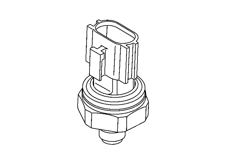
-
The refrigerant pressure sensor is installed to the high pressure pipe. Refer to Component Parts Location.
-
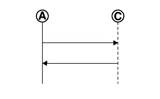
The refrigerant pressure sensor converts high-pressure side refrigerant pressure into voltage and outputs it to ECM.
-
This value is transmitted from the ECM to the A/C amp. via CAN communication and is used in A/C compressor control and cooling fan operation request control.
-
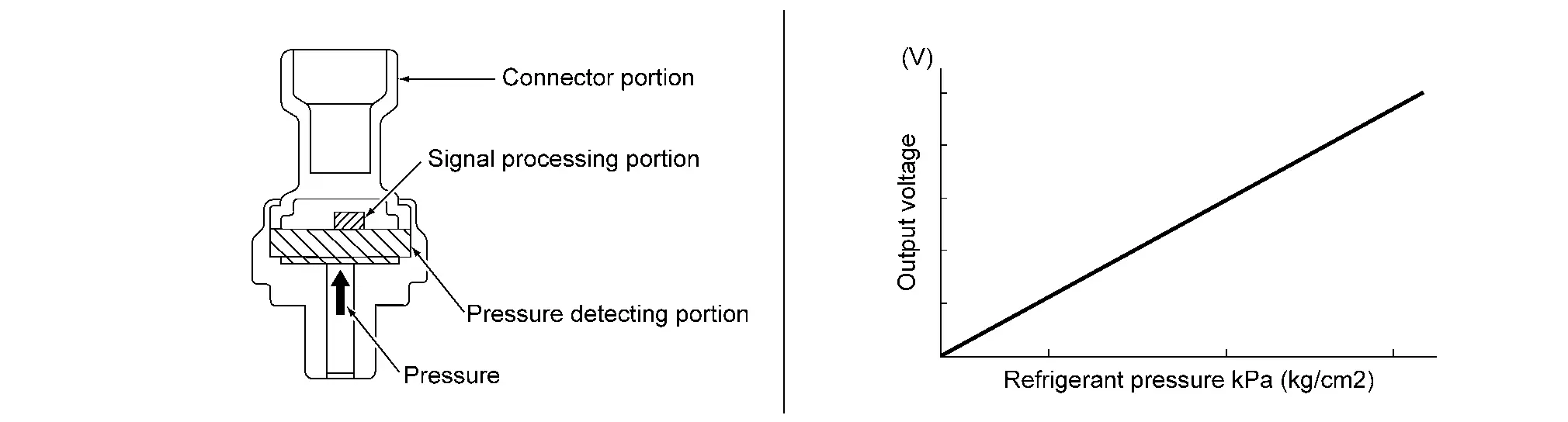
The refrigerant pressure sensor is a capacitance type sensor. It consists of a pressure detection area and a signal processing area.
-
The pressure detection area, which is a variable capacity condenser, changes internal static capacitance according to pressure force.
-
The signal processing area detects the static capacitance of the pressure detection area, converts the static capacitance into a voltage value, and transmits the voltage value to ECM.
-
The output voltage increases as the refrigerant pressure rises.
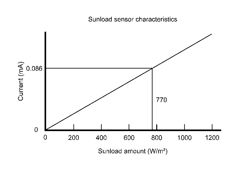
Sunload Sensor

-
The sunload sensor is installed to the instrument garnish. It measures sunload amount. Refer to Component Parts Location.
-
The sunload sensor measures the sunload and outputs the sunload sensor signal to the A/C amp. This sensor uses a photodiode with an electrical current that increases as the sunload increases.
Air Mix Door Motor LH
-
The air mix door motor LH is installed to the heater & cooling unit assembly. Refer to Component Parts Location.
-
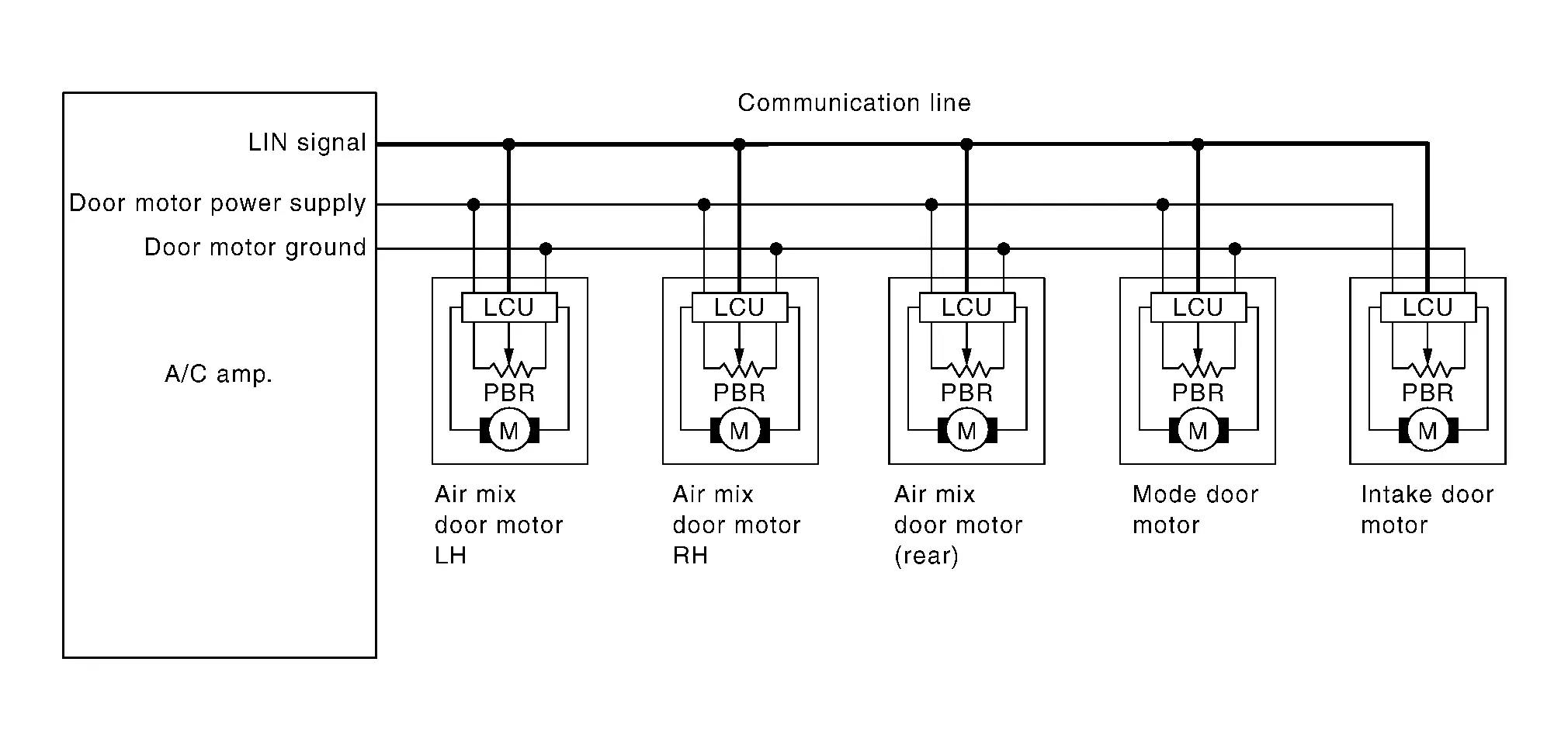
Air mix door motor LH consists of motor that drives door, PBR (Potentio Balance Register) that detects door position and LCU (Local Control Unit) that perform multiplex communication control (LIN) with A/C amp.
-
Rotation of motor is transmitted to front air mix door (driver side). Air flow temperature is switched.
-
LCU (Local Control Unit) is built into air mix door motor LH. And detects door position by PBR (Potentio Balance Resistor).
-
A/C amp. communicates with each LCU via communication line. And receives air mix door LH position feedback signal from LCU.
-
LCU transmits the signal of door movement completion to A/C amp., when the door movement is completed.
Air Mix Door Motor RH
-
The air mix door motor RH is installed to the heater & cooling unit assembly. Refer to Component Parts Location.
-
Air mix door motor RH consists of motor that drives door, PBR (Potentio Balance Register) that detects door position and LCU (Local Control Unit) that perform multiplex communication control (LIN) with A/C amp.
-
Rotation of motor is transmitted to front air mix door (passenger side). Air flow temperature is switched.
-
LCU (Local Control Unit) is built into air mix door motor RH. And detects door position by PBR (Potentio Balance Resistor).
-
A/C amp. communicates with each LCU via communication line. And receives air mix door RH position feedback signal from LCU.
-
LCU transmits the signal of door movement completion to A/C amp., when the door movement is completed.
Air Mix Door Motor (Rear)
-
The air mix door motor (rear) is installed to the heater & cooling unit assembly. Refer to Component Parts Location.
-
Air mix door motor (rear) consists of motor that drives door, PBR (Potentio Balance Register) that detects door position and LCU (Local Control Unit) that perform multiplex communication control (LIN) with A/C amp.
-
Rotation of motor is transmitted to rear air mix door. Air flow temperature is switched.
-
LCU (Local Control Unit) is built into air mix door motor (rear). And detects door position by PBR (Potentio Balance Resistor).
-
A/C amp. communicates with each LCU via communication line. And receives air mix door (rear) position feedback signal from LCU.
-
LCU transmits the signal of door movement completion to A/C amp., when the door movement is completed.
Front Blower Motor
-
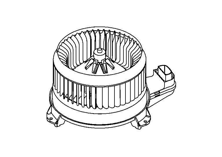
The front blower motor is installed to the blower unit assembly. Refer to Component Parts Location.
-
The rotation speed is changed according to the voltage controlled by the A/C amp. and the air flow rate is controlled.
-
The motor with the sirocco fan rotates, taking in-Nissan Ariya vehicle or ambient air and sending it into the passenger room.
-
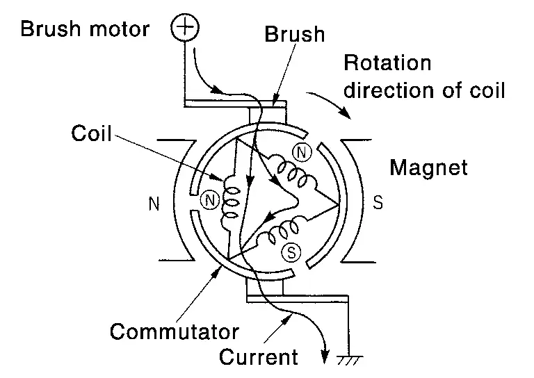
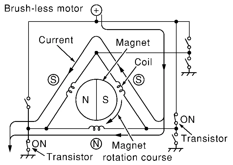
The front blower motor adopts the brush-less.
NOTE:
-
Brush motor rotates the coil while the brush functions as contact point.
-
Brush-less motor, the magnet part rotates.
-
Intake Door Motor
-
The intake door motor is installed to the blower unit assembly. Refer to Component Parts Location.
-
Intake door motor consists of motor that drives door, PBR (Potentio Balance Register) that detects door position and LCU (Local Control Unit) that perform multiplex communication control (LIN) with A/C amp.
-
Rotation of motor is transmitted to intake door. Air inlet is switched.
-
LCU (Local Control Unit) is built into intake door motor. And detects door position by PBR (Potentio Balance Resistor).
-
A/C amp. communicates with each LCU via communication line. And receives intake door position feedback signal from LCU.
-
LCU transmits the signal of door movement completion to A/C amp., when the door movement is completed.
Mode Door Motor
-
The mode door motor is installed to the heater & cooling unit assembly. Refer to Component Parts Location.
-
Mode door motor consists of motor that drives door, PBR (Potentio Balance Register) that detects door position and LCU (Local Control Unit) that perform multiplex communication control (LIN) with A/C amp.
-
Rotation of motor is transmitted to each mode door. Air outlet is switched.
-
LCU (Local Control Unit) is built into mode door motor. And detects door position by PBR (Potentio Balance Resistor).
-
A/C amp. communicates with each LCU via communication line. And receives each mode door position feedback signal from LCU.
-
LCU transmits the signal of door movement completion to A/C amp., when the door movement is completed.
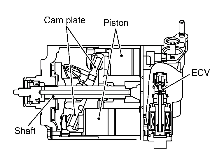
A/C Compressor
-
The A/C compressor is installed to the engine. Refer to Component Parts Location.
-
IPDM E/R controls the magnetic clutch and ECV (electrical control valve) according to the requests from the A/C amp. and ECM, and changes the A/C compressor drive and refrigerant discharge amount.
-
For controlling the A/C compressor, a magnetic clutch
 that drives the A/C compressor is used, together with an ECV
  that changes the refrigerant discharge amount.
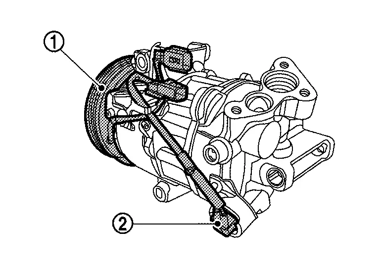
-
The magnetic clutch turns ON/OFF, transmitting the rotational motion of the engine to the A/C compressor.
-
Changing the cam plate angle, the ECV (Electrical Control Valve) changes the piston stroke and controls the refrigerant discharge amount.
Magnetic Clutch
-
Magnetic clutch consists of pulley, clutch disc, and field coil.
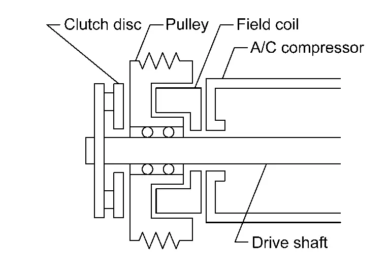
-
Pulley is connected with crankshaft pulley of engine via drive belt and is always rotated while engine is running.
-
Clutch disc is connected with drive shaft of A/C compressor.
-
Field coil, which becomes a strong electric magnet when electricity is supplied, strongly pulls clutch disc and presses it to pulley.
-
-
When Smart FET integrated in IPDM E/R turns ON, electricity is supplied to field coil, clutch disc is presses to pulley, and engine rotational movement is transmitted from crankshaft pulley ⇒ drive belt ⇒ pulley ⇒ clutch disc ⇒ drive shaft. A/C compressor is operated. When Smart FET turns OFF, electricity is not supplied to field coil, and clutch disc is released from pulley. A/C compressor is not operated.
ECV (Electrical Control Valve)
-
ECV (Electrical Control Valve) is integrated in the A/C compressor. IPDM E/R receives the ECV control signal from A/C amp. via CAN communication, and ECV is controlled according to the control signal transmitted from IPDM E/R.
-
ECV is controlled according to the control signal transmitted from IPDM E/R.
The control signal transmitted by IPDM E/R is controlled according to the ECV control signal transmitted from A/C amp. via CAN communication.
-
ECV varies the refrigerant pressure balance in the left and right refrigerant spaces that are divided by the cam plate in order to change the angle of the cam plate inside the A/C compressor.
By changing the cam plate angle, it changes the piston stroke and controls the refrigerant discharge amount.
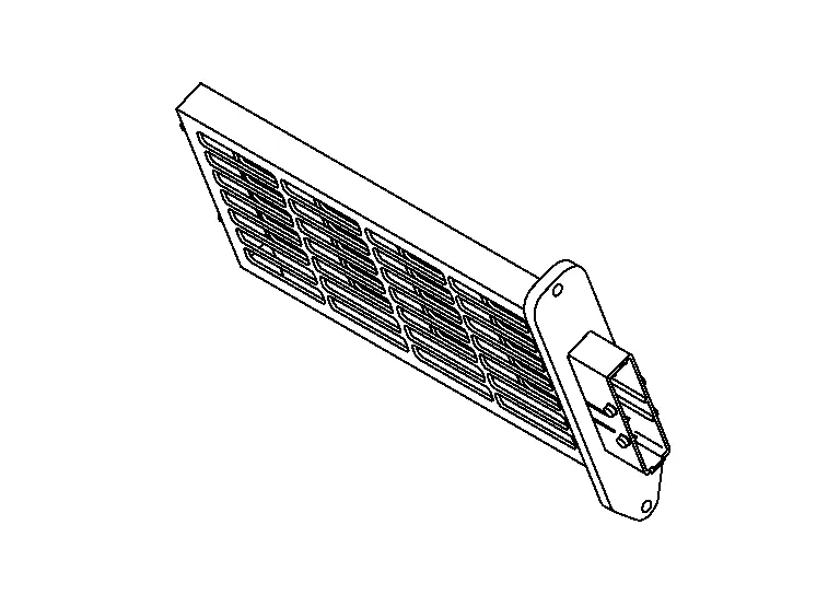
PTC Heater
-
The PTC heater is installed to the heater & cooling unit assembly. Refer to Component Parts Location.
-
Heat element is heated and air flow temperature is increased by power supply from BCM controlled PTC heater relay.
-
The PTC heater utilizes a PTC element is adopted.
NOTE:
The PTC
thermistor
generates heat in response to current flow. The temperature (and
resistance) of the thermistor element varies with current flow.
Excessive current flow will cause the element's temperature to rise.
When the temperature reaches a specified level, the electrical
resistance will rise sharply to control the circuit current.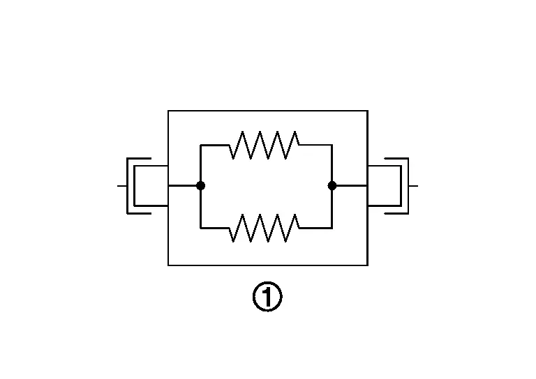
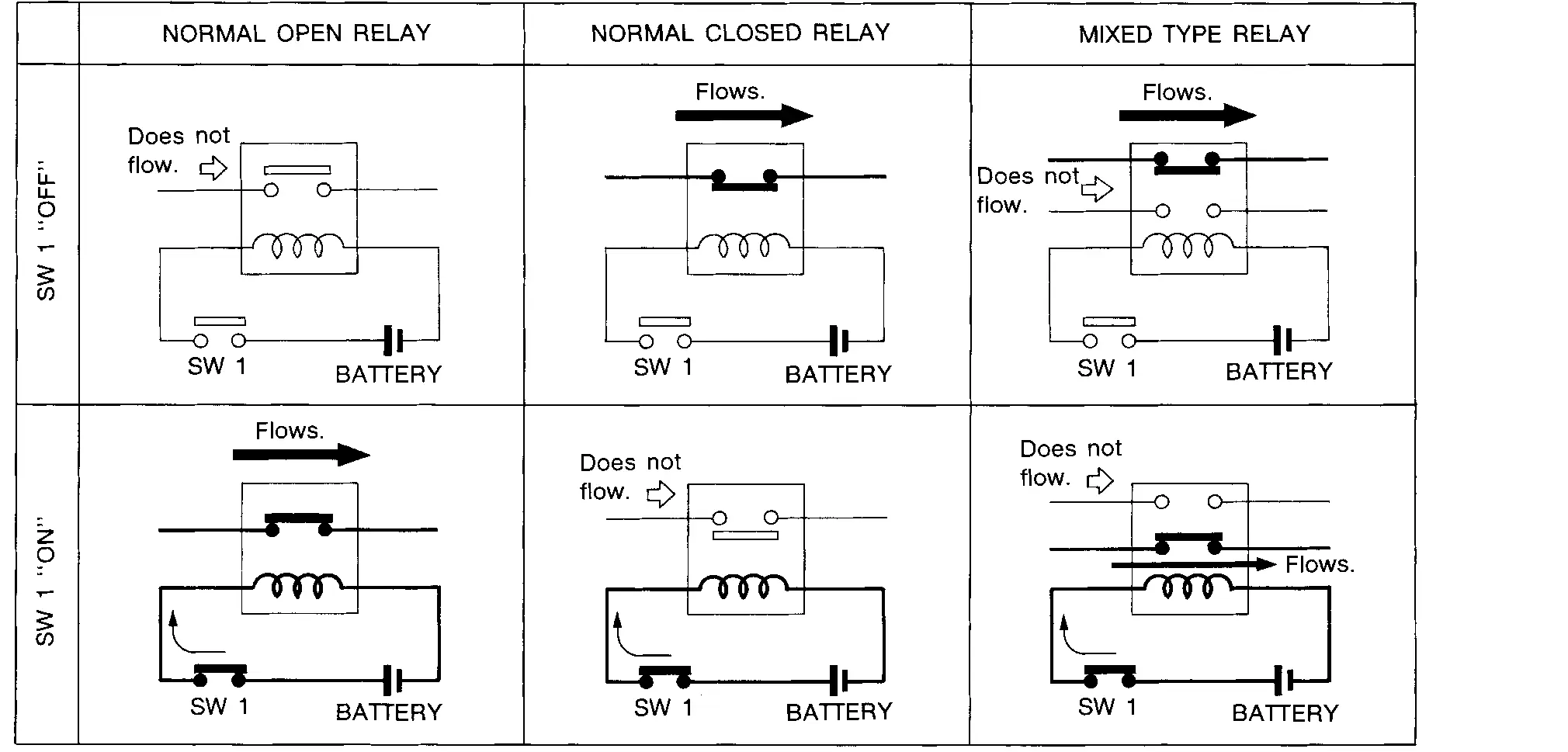
PTC Heater Relay
COMPONENT FUNCTION WITHIN SYSTEM
-
The PTC heater relay is installed in the relay box, behind of the front bumper. Refer to Component Parts Location.
-
The relay activates according to the PTC heater relay control signal that is controlled by BCM, and activates the PTC heater.
-
The BCM turns the relay switch ON/OFF and sends a large current from the battery to the PTC heater.
-
The PTC heater relay utilizes multiple relays. It decides the PTC heater ON/OFF and the power supplied to the heating wires according to the ON/OFF combination of these relays.
-
The PTC heater relay utilizes a normal open relay.
Other materials:
Ecu Diagnosis Information. Ecm, Bcm, Intelligent Key Unit, Ipdm E/r
List of ECU Reference
ECU Reference
ECM
Values On The Diagnosis Tool
Values On The Diagnosis Tool
Physical Values
Physical Values
Fail-safe
Fail-safe
DTC Inspection Priority Chart
DTC Inspection Priority Chart
DTC Index
DTC Index
BCM
Reference Valu ...
Nissanconnect. Preparation. Preparation
Preparation
Commercial Service Tools
Tool Description
Power tool
Loosening screws
Always Replace With New Parts
Always Replace With New PartsNever Reuse These PartsPart CodeFor additional information:
Washer
-
ROOF ANTENNA EXPLODED VIEW
...
Its Can Communication 1 Circuit
Diagnosis Procedure
CHECK NETWORK DIAGNOSIS
Check the "Network diagnosis" results from CONSULT to see that the diagnostic CAN communication circuit have no malfunction.
Are the diagnostic CAN communication circuit normal?
YES>>
GO TO 2.
NO>>
Check and repair diagnostic CAN commu ...