Nissan Rogue (T33) 2021-Present Service Manual: System
Automatic Air Conditioning System
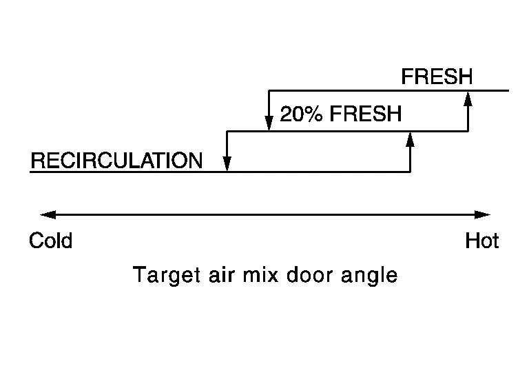
System Description
SYSTEM DIAGRAM
| Component | Function |
|---|---|
| ABS actuator and electric unit (control unit) | ABS actuator and electric unit (control unit) transmits Nissan Ariya vehicle speed signal to A/C amp. via CAN communication line. |
| AV control unit | AV control unit transmits blower reduction request signal to A/C amp. via CAN communication line. |
| A/C amp. | A/C Amp. |
| BCM |
|
| Combination meter | Combination meter transmits ambient temperature signal to A/C amp. via CAN communication line. |
| ECM |
|
| IPDM E/R |
|
| A/C switch assembly | A/C Switch Assembly |
| Rear air control* | Rear Air Control |
| Ambient sensor | Ambient Sensor |
| Intake sensor | Intake Sensor |
| In-Nissan Ariya vehicle sensor | In-vehicle Sensor |
| Refrigerant pressure sensor | Refrigerant Pressure Sensor |
| Sunload sensor | Sunload Sensor |
| Air mix door motor LH | Air Mix Door Motor LH |
| Air mix door motor RH | Air Mix Door Motor RH |
| Air mix door motor (Rear)* | Air Mix Door Motor (Rear) |
| Front blower motor | Front Blower Motor |
| Intake door motor | Intake Door Motor |
| Mode door motor | Mode Door Motor |
| A/C compressor | A/C Compressor |
| PTC heater | PTC Heater |
| PTC heater relay 1/2/3 | PTC Heater Relay |
*: With rear air control
INPUT SIGNAL AND OUTPUT SIGNAL
| Control unit | Signal status |
|---|---|
| A/C amp. |
|
| ABS actuator and electric unit (control unit) | Transmits the Nissan Ariya vehicle speed signal to A/C amp. via CAN communication. |
| AV control unit | Transmits the blower reduction request signal to A/C amp. via CAN communication. |
| BCM | Transmits the remote engine start status signal to A/C amp. via CAN communication. |
| Combination meter | Transmits the ambient temperature signal to A/C amp. via CAN communication. |
| ECM |
|
| IPDM E/R | Receives mainly the ECV control signal from A/C amp. via CAN communication. |
| A/C switch assembly |
|
| Rear air control* |
|
| Air mix door motor LH |
|
| Air mix door motor RH | |
| Air mix door motor (Rear)* | |
| Intake door motor | |
| Mode door motor |
*: With rear air control
DESCRIPTION
-
Automatic air conditioning system is controlled by each function of A/C amp., ECM and IPDM E/R.
-
Each operation of air conditioning system can be controlled by the A/C switch assembly.
-
BCM performs PTC heater relay ON/OFF control based on engine speed, engine coolant temperature, ambient temperature, electrical power cut freeze signal (permission signal, retention signal, stop signal), PTC thermal request signal, battery voltage, and electrical load state (high beam request, low beam request, and others).
-
When PTC heater relay turns ON, power supply is supplied to PTC heater. Heating element is heated and air flow temperature is increased. Heating is available for a period of time until engine coolant temperature is increased when engine starts cold in cold climate.
-
Idle up request signal is transmitted from A/C amp. to ECM while PTC heater operates. Idle speed is increased, warming-up is facilitated, and battery electric power is obtained.
-
Electric power supplied to PTC heating element is subject to PTC heater relay control conditions.
PTC heater Operation PTC heater relay 1 PTC heater relay 2 PTC heater relay 3 OFF OFF OFF OFF OFF PTC heater-1 LOW ON OFF OFF PTC heater-2 MID ON ON OFF PTC heater-3 HI ON ON ON
 NOTE:
NOTE:
PTC heater operation depends on ambient temperature and battery voltage. PTC heater is ON when ambient temperature is 8┬░C (46.4┬░F) or less. PTC heater is OFF when ambient temperature is 12┬░C (53.6┬░F) or more. The operating voltage of the PTC heater ON/OFF changes depending on the electrical load of the Nissan Ariya vehicle or battery voltage.
CONTROL BY A/C AMP.
-
Temperature Control
-
Air Outlet Control
-
Air Inlet Control
-
Door Control
-
Air Flow Control
-
A/C Compressor Control
-
Cooling Fan Operation Request Control
-
Remote Engine Start Control
CORRECTION FOR INPUT VALUE
-
Ambient temperature correction
-
A/C amp. inputs the temperature detected by ambient temperature signal received from combination meter via CAN communication as the ambient temperature.
-
A/C amp. performs the correction of the temperature detected by ambient sensor for air conditioning control.
-
A/C amp. selects and uses the initial value of ambient temperature data depending on the engine coolant temperature when placing the ignition switch from OFF to ON. The detection temperature of the ambient sensor is used when engine coolant temperature is low [less than approximately 56┬░C (133┬░F)]. The memory data (before the ignition switch is OFF) when the engine is warmed up [approximately 56┬░C (133┬░F) or more].
-
The correction of the ambient temperature is not performed when the detection temperature of the ambient temperature is less than approximately ŌłÆ20┬░C (ŌĆō4┬░F).
-
-
In-Nissan Ariya vehicle temperature correction
-
A/C amp. inputs the temperature detected by in-vehicle sensor as the in-Nissan Ariya vehicle temperature.
-
A/C amp. performs the correction of the temperature detected by in-vehicle sensor for air conditioning control.
-
A/C amp. performs the correction so that the recognition passenger room temperature changes depending on the difference between the detected passenger room temperature and the recognition passenger room temperature. If the difference is large, the changing is early. The changing becomes slow as the difference becomes small.
-
-
Intake temperature correction
-
A/C amp. inputs the temperature detected by intake sensor as the intake temperature (evaporator temperature).
-
A/C amp. performs the correction of the temperature detected by intake sensor for air conditioning control.
-
A/C amp. performs the correction so that the recognition intake temperature changes depending on the difference between the detected intake temperature and the recognition intake temperature. If the difference is large, the changing is early. The changing becomes slow as the difference becomes small.
-
-
Sunload amount correction
-
A/C amp. inputs the sunload amount detected by sunload sensor.
-
A/C amp. performs the correction of the sunload amount detected by sunload sensor for air conditioning control.
-
When the sunload amount suddenly changes, for example when entering a tunnel, perform the correction so that the recognition sunload amount of the A/C amp. changes slowly.
-
-
Set temperature correction
-
A/C amp. performs the correction to the target temperature set by the A/C switch assembly so as to match the temperature felt by the passengers depending on the ambient temperature detected by ambient sensor and controls it so that the in-Nissan Ariya vehicle temperature is always the most suitable.
-
CONTROL BY ECM
A/C Compressor Control
CONTROL BY IPDM E/R
A/C Compressor Control
Temperature Control
-
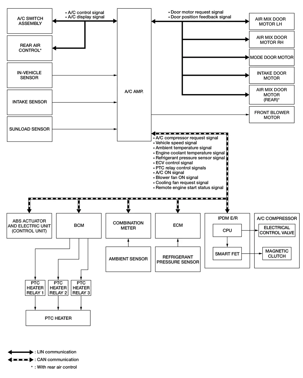
When ignition switch is in the ON position, A/C amp. always automatically controls temperature regardless of air conditioner operational state.
-
A/C amp. calculates the target air mix door opening angle depending on set temperature, in-Nissan Ariya vehicle temperature, ambient temperature, sunload and engine coolant temperature.
-
Air mix door is controlled depending on the comparison of current air mix door opening angle and target air mix door opening angle.
-
Regardless of in-Nissan Ariya vehicle temperature, ambient temperature, and sunload, air mix door is fixed at the fully cold position when set temperature is "Lo", and at the fully hot position when set temperature is "Hi".
Air Outlet Control
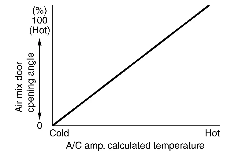
-
While air outlet is in automatic control, A/C amp. selects the mode door position depending on a target air mix door angle and outlet air temperature calculated from sunload.
-
If ambient temperature is excessively low, D/F is selected to prevent windshield fogging when air outlet is set to FOOT.
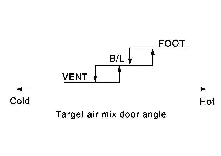
Air Inlet Control
-
A/C amp. controls intake door motor, and change air inlet.
-
While air inlet is in automatic control, A/C amp. selects air inlet (fresh air intake, 20% fresh air intake, or recirculation) depending on set temperature, in-Nissan Ariya vehicle temperature, and ambient temperature.
NOTE:
-
When air inlet is set to recirculation by manual control, the air inlet may be automatically changed to fresh air intake depending on Nissan Ariya vehicle condition (example: when ambient temperature and engine coolant temperature are low).
-
Air inlet may not be changed to recirculation by intake switch (indicator: ON) (with rear air control) or REC switch (without rear air control) depending on Nissan Ariya vehicle condition.
Door Control
SWITCH AND THEIR CONTROL FUNCTION
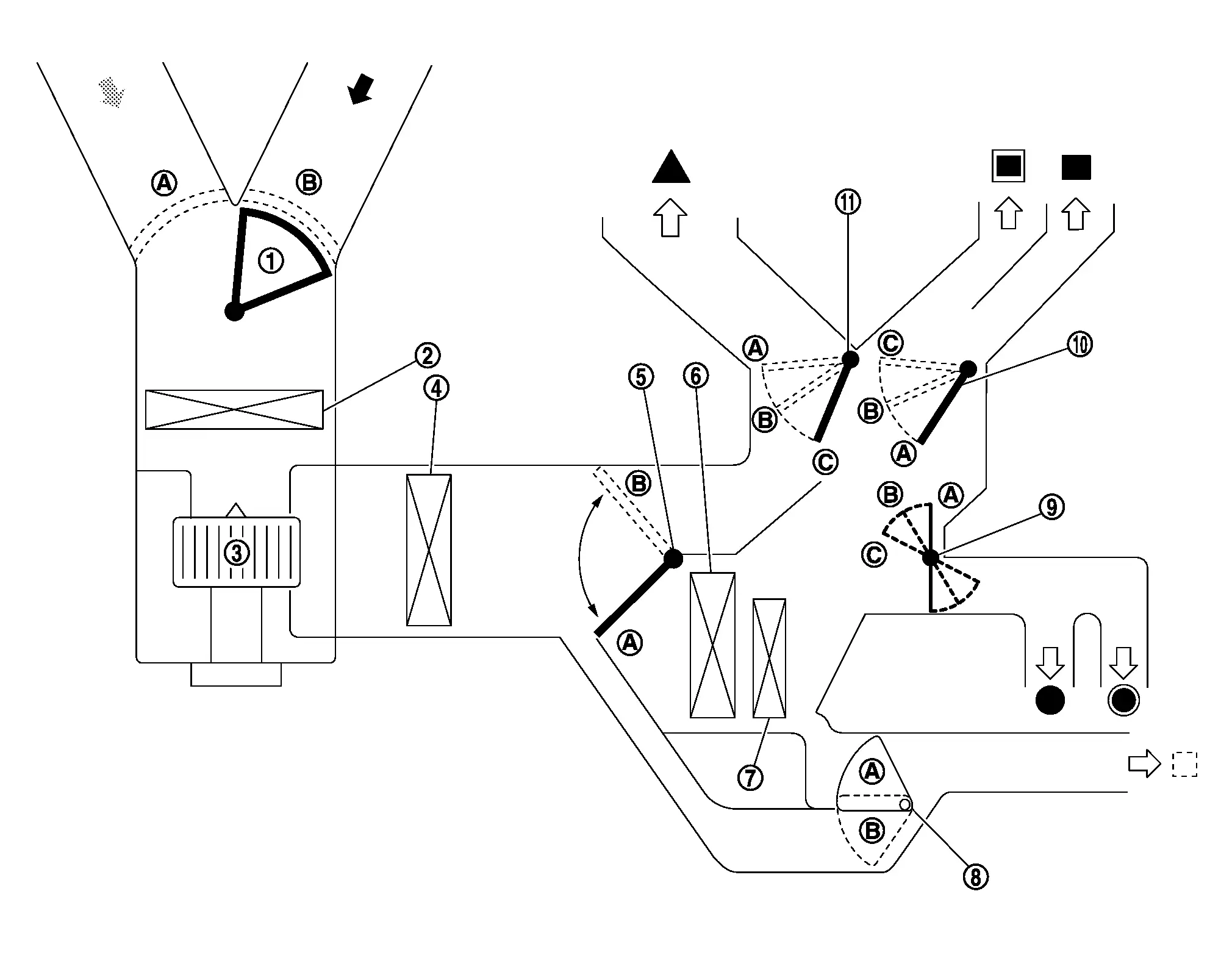
| 1. | Intake door | 2. | In-cabin microfilter | 3. | Front blower motor |
| 4. | Evaporator | 5. | Front air mix door (driver side/passenger side) | 6. | Heater core |
| 7. | PTC heater | 8. | Rear air mix door* | 9. | Foot door |
| 10. | Ventilator door | 11. | Defroster door | ||
 |
Fresh air |  |
Recirculation air | Discharge air | |
 |
Defroster |  |
Center ventilator |  |
Side ventilator |
 |
Rear ventilator |  |
Front foot |  |
Rear foot |
*: With rear air control
| Switch/dial position | Door position | |||||||||
|---|---|---|---|---|---|---|---|---|---|---|
| Mode door | Intake door | Front air mix door | Rear air mix door*2 | |||||||
| Ventilator door | Foot door | Defroster door | Driver side | Passenger side | ||||||
| AUTO switch | .webp) |
AUTO | ŌĆö | ŌĆö | ŌĆö | ŌĆö | ||||
| MODE switch |  |
 |
|
|
||||||
 |
 |
|
|
|||||||
 |
 |
|
(*4 or )*5 |
|||||||
 |
|
|
|
|||||||
| DEF switch |  |
|
|
|
|
|||||
| Intake switch*1 , *3 | REC |  |
|
ŌĆö | ŌĆö | ŌĆö | |
|||
| FRE | .webp) |
|
||||||||
| REC switch*1, *2 | |
|
|
|||||||
| FRE switch*1, *2 |  |
|
|
|||||||
| Temperature control dial (driver side) | SYNC switch: ON |
Full cold "Lo" |
ŌĆö | |
||||||
|
18.0┬░C ŌĆō 32.0┬░C (61┬░F ŌĆō 89┬░F) |
AUTO | |||||||||
|
Full hot "Hi" |
|
|||||||||
| Temperature control dial (driver side) | SYNC switch: OFF |
Full cold "Lo" |
|
ŌĆö | ŌĆö | |||||
|
18.0┬░C ŌĆō 32.0┬░C (61┬░F ŌĆō 89┬░F) |
AUTO | |||||||||
|
Full hot "Hi" |
|
|||||||||
| Temperature control dial (passenger side) |
Full cold "Lo" |
ŌĆö | |
|||||||
|
18.0┬░C ŌĆō 32.0┬░C (61┬░F ŌĆō 89┬░F) |
AUTO | |||||||||
|
Full hot "Hi" |
|
|||||||||
| Temperature control switch (rear side)*2 |
Full cold "Lo" |
ŌĆö | |
|||||||
|
18.0┬░C ŌĆō 32.0┬░C (61┬░F ŌĆō 89┬░F) |
AUTO | |||||||||
|
Full hot "Hi" |
|
|||||||||
| ON┬ĘOFF switch | OFF | |
|
(*4 or )*5 |
ŌĆö | |||||
*1: Air inlet status is displayed by indicator during activating automatic control
*2: With rear air control
*3: Without rear air control
*4: Default setting
*5: It can be changed using ŌĆ£Blower settingŌĆØ in ŌĆ£Work supportŌĆØ mode of "HVAC". Refer to CONSULT Function.
AIR DISTRIBUTION
| Discharge air flow | ||||||
|---|---|---|---|---|---|---|
| MODE position | Air outlet/distribution | |||||
| Ventilator | Foot | Defroster | ||||
| Front | Rear | Front | Rear | |||
| Center | Side | |||||
|
44% | 44% | 12% | ŌĆö | ŌĆö | ŌĆö |
|
23% | 23% | 15% | 30% | 9% | ŌĆö |
|
ŌĆö | 11% | 9% | 43% | 12% | 25% |
|
ŌĆö | 9% | 9% | 34% | 11% | 37% |
|
ŌĆö | 9% | 10% | ŌĆö | ŌĆö | 81% |
| Discharge air flow | ||||||
|---|---|---|---|---|---|---|
| MODE position | Air outlet/distribution | |||||
| Ventilator | Foot | Defroster | ||||
| Front | Rear | Front | Rear | |||
| Center | Side | |||||
|
45% | 43% | 12% | ŌĆö | ŌĆö | ŌĆö |
|
23% | 27% | 14% | 30% | 6% | ŌĆö |
|
ŌĆö | 9% | 18% | 36% | 12% | 25% |
|
ŌĆö | 8% | 15% | 30% | 11% | 36% |
|
ŌĆö | 6% | 15% | ŌĆö | ŌĆö | 79% |
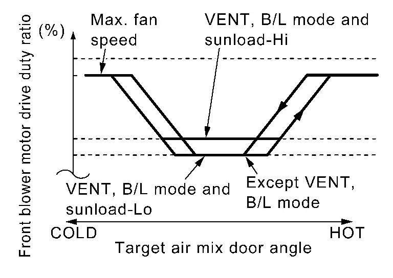
Air Flow Control
DESCRIPTION
-
A/C amp. changes duty ratio of front blower motor control signal and controls air flow continuously. When air flow is increased, duty ratio of front blower motor control signal gradually increases to prevent a sudden increase in air flow.
-
In addition to manual control and automatic control, air flow control is compose of starting fan speed control, low coolant temperature starting control, high in-Nissan Ariya vehicle temperature starting control, and blower speed control at door motor operation and fan speed control at voice recognition.
AUTOMATIC AIR FLOW CONTROL
-
A/C amp. decides target air flow depending on target air mix door opening angle.
-
A/C amp. changes duty ratio of front blower motor control signal and controls air flow continuously so that air flow matches to target air flow.
-
When air outlet is VENT or B/L, the minimum air flow is changed depending on sunload.
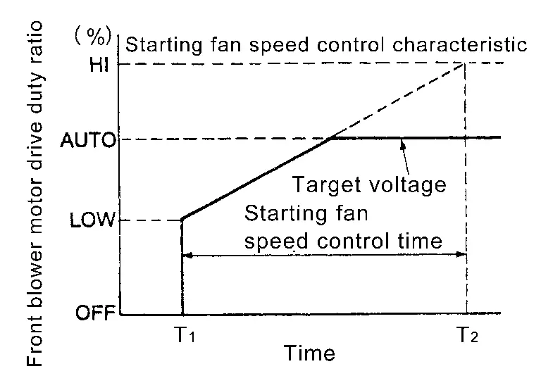
STARTING FAN SPEED CONTROL
When front blower motor is activated, A/C amp. gradually increases voltage of front blower motor to prevent a sudden increase in discharge air flow. (T1 ŌĆō T2 = approximately 8 seconds)
NOTE:
Do not perform the starting air flow control when the air outlet is set to DEF.
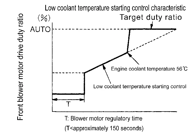
LOW COOLANT TEMPERATURE STARTING CONTROL
If the engine coolant temperature is 56┬░C (133┬░F) or less, to prevent a cold discharged air flow, A/C amp. reduces air flow front blower motor activation for the maximum 150 seconds depending on target air mix door opening angle. After this, voltage of front blower motor is increased gradually, and front blower motor is activated. Air may be directed automatically to the windshield during front blower motor limited operation.
HIGH IN-VEHICLE TEMPERATURE STARTING CONTROL
When evaporator temperature is high [intake sensor value is 35┬░C (95┬░F) or more], to prevent a hot discharged air flow, A/C amp. suspends front blower motor activation for approximately 3 seconds so that evaporator is cooled by refrigerant.
FAN SPEED CONTROL AT DOOR MOTOR OPERATION
When mode door motor is activated while air flow is more than the specified value, A/C amp. reduces temporarily fan speed so that mode door moves smoothly.
FAN SPEED CONTROL AT VOICE RECOGNITION
When the voice control (voice command) switch is operated during air flow automatic control, A/C amp. decreases the air flow of the front blower motor once and controls the air flow so as not to disturb the voice recognition function. This control continues while voice recognition function is operating.
A/C Compressor Control
DESCRIPTION
-
When the A/C compressor activation condition is satisfied while front blower motor is activated, A/C amp. transmits A/C ON signal and blower fan ON signal to ECM.
-
ECM judges the conditions of each sensor (Refrigerant pressure sensor signal, accelerator position signal, etc.), and transmits the A/C compressor request signal to IPDM E/R via CAN communication line.
-
By receiving the A/C compressor request signal from ECM, IPDM E/R turns the Smart FET to ON, and activates the A/C compressor. Refer to System Description.
CONTROL BY A/C AMP.
Low Temperature Protection Control
When intake sensor detects that evaporator fin temperature is  [ŌłÆ5.0┬░C (23.0┬░F)] or less, A/C amp. requests ECM to turn the A/C compressor OFF, and stops the A/C compressor.
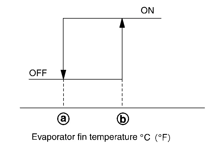
When the air temperature returns to  [ŌłÆ2.0┬░C (28.4┬░F)] or more, the A/C compressor is activated.
Refrigerant Discharge Amount Control
-
A/C amp. transmits the ECV control signal via CAN communication. IPDM E/R transmits the control signal to ECV according to the received ECV control signal.
-
ECV is controlled according to change in the duty ratio of the transmitted control signal.
-
Except when temperature setting is full cold or outlet is DEF, A/C amp. controls the refrigerant discharge amount according to the required cooling capacity.
-
A/C amp. increases the refrigerant discharge amount when evaporator temperature is higher than the target temperature upper limit, and reduces the refrigerant discharge amount when evaporator temperature is at or below the target temperature upper limit.
NOTE:
Target temperature upper limit value of evaporator can be changed using ŌĆ£Target evaporator temperature upper limit settingŌĆØ in ŌĆ£Work supportŌĆØ mode of "HVAC". Refer to CONSULT Function.
A/C Compressor Oil Circulation Control
When the engine starts, A/C amp. activates the A/C compressor for a few seconds and circulates the A/C compressor oil once.
CONTROL BY ECM
A/C Compressor Protection Control at Pressure Malfunction
The high-pressure side value that is detected by refrigerant pressure sensor is excessively low or high, ECM requests IPDM E/R to turn Smart FET OFF and stop the A/C compressor.
Air Conditioning Cut Control
When the engine condition is high load, ECM transmit Smart FET OFF request to IPDM E/R, and stops the A/C compressor.
Cooling Fan Operation Request Control
DESCRIPTION
A/C amp. controls the cooling fan operation request according to the refrigerant pressure status and Nissan Ariya vehicle speed status.
NOTE:
For an overview of the cooling fan and information about control. Refer to System Description (Cooling Fan Control System).
CONTROL OUTLINE
-
A/C amp. receives the refrigerant pressure sensor signal from ECM via CAN communication and Nissan Ariya vehicle speed signal from the ABS actuator and electric unit (control unit) via CAN communication.
-
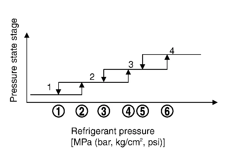
A/C amp. sets one of the optionally determined stages according to the received refrigerant pressure sensor signal and Nissan Ariya vehicle speed signal.
NOTE:
For the rules that prescribe the predetermined stages, refer to the following figures:
-
Nissan Ariya Vehicle speed stages
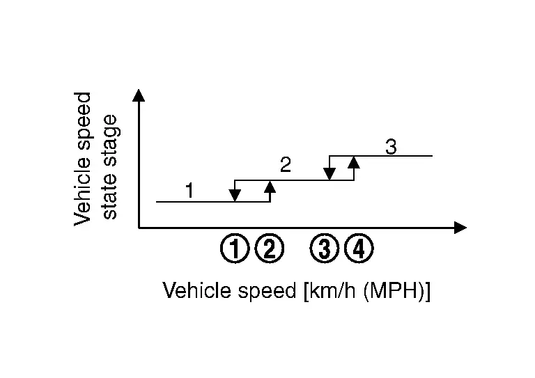
Vehicle speed [(MPH) km/h]
-
 : 7.5 (12)
 -
 : 12 (20)
 -
 : 45 (72)
 -
 : 50 (80)
-
-
Refrigerant pressure stages
Refrigerant pressure [MPa (bar, kg/cm2, psi)]
-
: 1.28 (12.8, 13.1, 186)
-
: 1.28 (12.8, 13.1, 186)
-
: 1.28 (12.8, 13.1, 186)
-
: 1.28 (12.8, 13.1, 186)
-
 : 1.28 (12.8, 13.1, 186)
 -
 : 1.58 (15.8, 16.1, 229)
-
-
-
The requested cooling fan operation strength (0%, 40%, 100%) is determined according to the combination of these two stages, and the request signal is transmitted to ECM via CAN communication.
Remote Engine Start Control
A/C amp. operates air conditioning system in following mode according to the vehicle situation when remote engine start function is operated. For an overall description of the remote engine start function. Refer to System Description.
| Conditions | Cooler mode | Normal mode | Defrost mode | Heated normal mode | |
|---|---|---|---|---|---|
| Nissan Ariya Vehicle situation |
Air mix door opening angle*1 (COLD Ōćö HOT) | When XM*2 is changed while defrost mode | |||
| Air conditioning control | Air flow | AUTO | AUTO | AUTO | AUTO |
| Air outlet | AUTO | AUTO | DEF | AUTO | |
| Air inlet | AUTO | AUTO | AUTO | AUTO | |
| A/C compressor | ON | Depend on A/C request | Depend on A/C request | Depend on A/C request | |
| Setting temperature (driver side) | 25┬░C (77┬░F) | 25┬░C (77┬░F) | 25┬░C (77┬░F) | 25┬░C (77┬░F) | |
| Setting temperature (passenger side) | 25┬░C (77┬░F) | 25┬░C (77┬░F) | 25┬░C (77┬░F) | 25┬░C (77┬░F) | |
| Setting temperature (rear side) | 25┬░C (77┬░F) | 25┬░C (77┬░F) | 25┬░C (77┬░F) | 25┬░C (77┬░F) | |
| SYNC | ON | ON | ON | ON | |
| Other control | Heated steering wheel control | OFF | OFF | ON | No change |
| Heated seat control | OFF | OFF | AUTO | No change | |
| Rear window defogger control | OFF | OFF | ON | No change | |
| A/C switch assembly | Switch indicator lamp / Display | OFF | OFF | OFF | OFF |
| Switch operation | Not accepted | Not accepted | Not accepted | Not accepted | |
*1: For details of air mix door opening angle. Refer to Temperature Control.
*2: The reading of XM can be checked by the data monitor of CONSULT.
Remote engine start control OFF condition (When any of the following conditions are satisfied)
-
Remote engine start function: Stop
-
Ignition switch: OFF
Other materials:
P0030 A/f Sensor 1 Heater
DTC Description
DTC DETECTION LOGIC DTC
CONSULT screen terms
(Trouble diagnosis content)
DTC detection condition
P0030
00
HO2S1 HTR (B1)
(HO2S heater control circuit bank 1 sensor 1)
Diagnosis condition
Engine running at idle
Signal (terminal)
A/F sensor 1 heater ...
U214a Can Comm Circuit
DTC Description
DTC DETECTION LOGIC DTC
CONSULT screen terms
(Trouble diagnosis content)
DTC detection condition
U214A
83
CAN comm err (AWD/4WD)
[CAN comm err (AWD/4WD)]
Diagnosis condition
Ignition switch ON
Signal (terminal)
CAN communication signal
87
T ...
P1c90-49 Sub Starter & Generator
DTC Description
DTC DETECTION LOGIC DTC No. CONSULT screen terms (Trouble diagnosis content) DTC detection condition
P1C90-49
Sub starter & generator
(Sub starter & generator)
Diagnosis condition
Engine running at idle
Signal (terminal)
-
Threshold
Sub starte ...