Nissan Rogue (T33) 2021-Present Service Manual: Ecu Diagnosis Information :: Sonar Control Unit
Reference Value
VALUES ON THE DIAGNOSIS TOOL
 NOTE:
NOTE:
The following table includes information (items) inapplicable to this Nissan Ariya vehicle. For information (items) applicable to this vehicle, refer to CONSULT display items.
| Monitor Item | Condition | Value/Status | |
|---|---|---|---|
| Discontinuous tone area (near) | Ignition switch ON |
This item is displayed, but cannot be monitored. |
60 cm |
| Detection Mode | Ignition switch ON |
This item is displayed, but cannot be monitored. |
MODE 3 |
| Sonar control unit power supply voltage | Ignition switch ON | Input value of battery voltage | |
| Nissan Ariya Vehicle speed (meter) | While driving | Input value of Nissan Ariya vehicle speed signal | |
| Discontinuous tone area (far) 2 | Ignition switch ON |
This item is displayed, but cannot be monitored. |
40 cm |
| Discontinuous tone area (far) 1 | Ignition switch ON |
This item is displayed, but cannot be monitored. |
40 cm |
| Corner sensor rear right hand 1 | Ignition switch ON | Distance between rear bumper and obstacle. | |
| Center sensor rear right hand | Ignition switch ON | Distance between rear bumper and obstacle. | |
| Corner sensor rear right hand 2 | Ignition switch ON | Distance between rear bumper and obstacle. | |
| Corner sensor rear right | Ignition switch ON | Distance between rear bumper and obstacle. | |
| Corner sensor rear right->center sensor rear right/rear center sensor | Ignition switch ON | When obstacles exist around rear bumper. | Distance between rear bumper and obstacle. |
| Center sensor rear right/front center sensor->corner sensor rear right | Ignition switch ON | When obstacles exist around rear bumper. | Distance between rear bumper and obstacle. |
| Center sensor rear right | Ignition switch ON | Distance between rear bumper and obstacle. | |
| Center sensor rear right->center sensor rear left | Ignition switch ON | When obstacles exist around rear bumper. | Distance between rear bumper and obstacle. |
| Center sensor rear left->center sensor rear right | Ignition switch ON | When obstacles exist around rear bumper. | Distance between rear bumper and obstacle. |
| Center sensor rear left/rear center sensor | Ignition switch ON | When obstacles exist around rear bumper. | Distance between rear bumper and obstacle. |
| Center sensor rear left/rear center sensor->center sensor rear left | Ignition switch ON | When obstacles exist around rear bumper. | Distance between rear bumper and obstacle. |
| Corner sensor rear left->center sensor rear left/rear center sensor | Ignition switch ON | When obstacles exist around rear bumper. | Distance between rear bumper and obstacle. |
| Corner sensor rear left | Ignition switch ON | Distance between rear bumper and obstacle. | |
| Corner sensor rear left hand 2 | Ignition switch ON | Distance between rear bumper and obstacle. | |
| Center sensor rear left hand | Ignition switch ON | Distance between rear bumper and obstacle. | |
| Corner sensor rear left hand 1 | Ignition switch ON | Distance between rear bumper and obstacle. | |
| Shortest distance from rear sensors | Ignition switch ON | When obstacles exist around rear bumper. | Distance between rear bumper and obstacle. |
| Timeout for scan zones | Ignition switch ON |
This item is displayed, but cannot be monitored. |
2 second |
| Driving corridor high angle | Ignition switch ON |
This item is displayed, but cannot be monitored. |
30 deg |
| Driving corridor low angle | Ignition switch ON |
This item is displayed, but cannot be monitored. |
5 deg |
| Limit angle | Ignition switch ON |
This item is displayed, but cannot be monitored. |
15 deg |
| Corner sensor front right hand 1 | Ignition switch ON | Distance between rear bumper and obstacle. | |
| Center sensor front right hand | Ignition switch ON | Distance between rear bumper and obstacle. | |
| Corner sensor front right hand 2 | Ignition switch ON | Distance between rear bumper and obstacle. | |
| Corner sensor front right | Ignition switch ON | Distance between rear bumper and obstacle. | |
| Corner sensor front right->center sensor front right/front center sensor | Ignition switch ON | When obstacles exist around front bumper. | Distance between front bumper and obstacle. |
| Center sensor front right/front center sensor->corner sensor front right | Ignition switch ON | When obstacles exist around front bumper. | Distance between front bumper and obstacle. |
| Center sensor front right | Ignition switch ON | Distance between rear bumper and obstacle. | |
| Center sensor front right->center sensor front left | Ignition switch ON | When obstacles exist around front bumper. | Distance between front bumper and obstacle. |
| Center sensor front left->center sensor front right | Ignition switch ON | When obstacles exist around front bumper. | Distance between front bumper and obstacle. |
| Center sensor front left/front center sensor | Ignition switch ON |
When an obstacle is detected by front sonar sensor LH inner. [Approx. 27 - 100 cm (Approx. 10.63 - 39.73 in)] |
Distance between sensor and obstacle. [Approx. 27 - 100 cm (Approx. 10.63 - 39.73 in)] |
| When no obstacles exist around front sonar sensor LH inner. | 255 cm (100.39 in) | ||
| Center sensor front left/front center sensor->Corner sensor front left | Ignition switch ON | When obstacles exist around front bumper. | Distance between front bumper and obstacle. |
| Corner sensor front left->center sensor front left/front center sensor | Ignition switch ON | When obstacles exist around front bumper. | Distance between front bumper and obstacle. |
| Corner sensor front left | Ignition switch ON | Distance between frontbumper and obstacle. | |
| Corner sensor front left hand 2 | Ignition switch ON | Distance between frontbumper and obstacle. | |
| Center sensor front left hand | Ignition switch ON | Distance between frontbumper and obstacle. | |
| Corner sensor front left hand 1 | Ignition switch ON | Distance between frontbumper and obstacle. | |
| LED | Ignition switch ON |
This item is displayed, but cannot be monitored. |
Off |
| Continuous tone area | Ignition switch ON |
This item is displayed, but cannot be monitored. |
30 cm |
TERMINAL LAYOUT
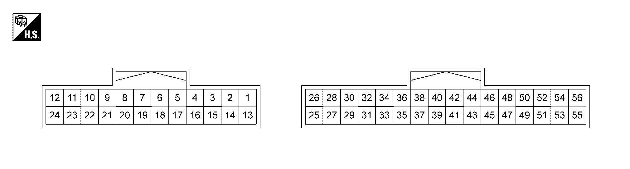
PHYSICAL VALUES
|
Terminal (Wire color) | Description | Condition | Standard |
Reference value (Approx.) | ||
|---|---|---|---|---|---|---|
| + | – | Signal name | Input/Output | |||
|
1 (LA/LG) |
13 (LA/L) |
Front sonar sensor signal RH inner | Input |
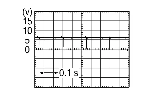
[Ignition switch ON]
|
Waveform according to sensor signal is input |
|
|
2 (LA/G) |
13 (LA/L) |
Front sonar sensor signal LH inner | Input |
[Ignition switch ON]
|
Waveform according to sensor signal is input |
|
|
3 (LA/R) |
13 (LA/L) |
Front sonar sensor signal LH outer | Input |
[Ignition switch ON]
|
Waveform according to sensor signal is input |
|
|
4 (LA/Y) |
13 (LA/L) |
Front sonar sensor signal RH outer | Input |
[Ignition switch ON]
|
Waveform according to sensor signal is input |
|
|
5 (BR) |
— | CAN–High | Input/Output | — | — | — |
|
6 (W) |
— | CAN–Low | Input/Output | — | — | — |
|
9 (LA/B) |
14 (LA/GR) |
Rear sonar sensor signal RH inner | Input |
[Ignition switch ON]
|
Waveform according to sensor signal is input |
|
|
10 (LA/P) |
14 (LA/GR) |
Rear sonar sensor signal RH outer | Input |
[Ignition switch ON]
|
Waveform according to sensor signal is input |
|
|
11 (LA/SB) |
13 (LA/L) |
Front sensor power supply | Output | [Ignition switch ON] | — | 8.0 V |
|
12 (LA/G) |
15 (B) |
ACC power supply | Input | [Ignition switch ACC] | 9.0 - 16.0 V | Battery voltage |
|
13 (LA/L) |
Ground | Front sensor ground | — | [Ignition switch ON] | — | 0 V |
|
14 (LA/GR) |
Ground | Rear sensor ground | — | [Ignition switch ON] | — | 0 V |
|
15 (B) |
Ground | Ground | — | [Ignition switch ON] | — | 0 V |
|
21 (LA/G) |
14 (LA/GR) |
Rear sonar sensor signal LH inner | Input |
[Ignition switch ON]
|
Waveform according to sensor signal is input |
|
|
22 (LA/LG) |
14 (LA/GR) |
Rear sonar sensor signal LH outer | Input |
[Ignition switch ON]
|
Waveform according to sensor signal is input |
|
|
23 (LA/L) |
14 (LA/GR) |
Rear sensor power supply | Output | [Ignition switch ON] | — | 8.0 V |
|
26 (Y) |
— | CAN–Low | Input/Output | — | — | — |
|
28 (BR) |
— | CAN–High | Input/Output | — | — | — |
|
49 (LA/L) |
14 (LA/GR) |
Rear sonar sensor signal LH side | Input |
[Ignition switch ON]
|
Waveform according to sensor signal is input |
|
|
50 (LA/SB) |
14 (LA/GR) |
Rear sonar sensor signal RH side | Input |
[Ignition switch ON]
|
Waveform according to sensor signal is input |
|
Fail-Safe
Obstacle detection function is deactivated when a sensor system error is detected.
DTC Inspection Priority Chart
If multiple DTCs are detected simultaneously, check them one by one depending on the following DTC inspection priority chart.
| Priority | Detected items (DTC) | ||
|---|---|---|---|
| 1 | B273A | 55 | ECU Configuration |
| B2724 | 16/17/46/48/49/55 | SONAR CONTROL UNIT | |
| 2 | U1327 | 54 | MAC Key update |
| 3 | U1327 | 52 | MAC Key update |
| 4 | U214F | 57 | CAN comm err (IPDM E/R) |
| U2176 | 57 | CAN comm err (MAC) | |
| 5 | U2025 | 87 | CAN comm err (audio amp.) |
| U2140 | 87 | CAN comm err (ECM) | |
| U2141 | 87 | CAN comm err (TCM) | |
| U2148 | 87 | CAN comm err (brake control unit) | |
| U214E | 87 | CAN comm err (combination meter) | |
| U2152 | 87 | CAN comm err (ADAS control unit) | |
| U2154 | 87 | CAN comm err (MIU) | |
| U2156 | 87 | CAN comm err (steering angel sensor) | |
| U2159 | 87 | CAN comm err (steering control unit) | |
| U215B | 87 | CAN comm err (IPDM E/R) | |
| U2175 | 87 | CAN comm err (AVM) | |
| U2176 | 87 | CAN comm err (CCM) | |
| U2275 | 87 | CAN comm err (AVM) | |
| U2A05 | 88 | Comm Bus Off ITS4-FD | |
| U2A0A | 88 | Comm Bus Off ITS6-FD | |
| 6 | B2738 | 11/12/87 | Front Sensor Power Supply |
| B273B | 11/12/87 | Rear Sensor Power Supply | |
| 7 | B2720 | 05/11/12/16/17/34/43/47/49/61/65/68/81/83/88/92/93/97 | CORNER SENSOR [RL] |
| B2721 | 05/11/12/16/17/34/43/47/49/61/65/68/81/83/88/92/93/97 | CENTER SENSOR [RL] | |
| B2722 | 05/11/12/16/17/34/43/47/49/61/65/68/81/83/88/92/93/97 | CENTER SENSOR [RR] | |
| B2723 | 05/11/12/16/17/34/43/47/49/61/65/68/81/83/88/92/93/97 | CORNER SENSOR [RR] | |
| B2729 | 05/11/12/16/17/34/43/47/49/61/65/68/81/83/88/92/93/97 | CORNER SENSOR [FL] | |
| B272A | 05/11/12/16/17/34/43/47/49/61/65/68/81/83/88/92/93/97 | CENTER SENSOR [FL] | |
| B272B | 05/11/12/16/17/34/43/47/49/61/65/68/81/83/88/92/93/97 | CENTER SENSOR [FR] | |
| B272C | 05/11/12/16/17/34/43/47/49/61/65/68/81/83/88/92/93/97 | CORNER SENSOR [FR] | |
| B2730 | 05/11/12/13/16/17/21/29/34/35/43/47/49/61/65/68/81/83/88/92/93/95/96/97 | SIDE SENSOR [RL] | |
| B2731 | 05/11/12/13/16/17/21/29/34/35/43/47/49/61/65/68/81/83/88/92/93/95/96/97 | SIDE SENSOR [RR] | |
| B2740 | 82/83/86/87 | IPDM E/R | |
| B2744 | 82/83/87 | BCM | |
| B2746 | 82/83/87 | 4WAS | |
| B2747 | 82/83/87 | ECM | |
| B274A | 87 | Steering angle sensor | |
| B274B | 82/83/87 | ABS actuator and electric unit (control unit) | |
| B274C | 87 | ADAS control unit | |
| B274D | 87 | Combination meter | |
| B2750 | 87 | AV control unit | |
| B2752 | 87 | Audio amp. | |
| B2753 | 87 | Around view monitor control unit | |
| B2754 | 82/83/87 | Chassis control module | |
| B2755 | 94 | Front sensor | |
| B2756 | 94 | Rear sensor | |
DTC Index
Self diagnostic result
Ă—: Applicable
| DTC | Display item | Parking sensor error | Reference |
|---|---|---|---|
| B2720-05 | CORNER SENSOR [RL] | Ă— | DTC Description |
| B2720-11 | CORNER SENSOR [RL] | Ă— | DTC Description |
| B2720-12 | CORNER SENSOR [RL] | Ă— | DTC Description |
| B2720-16 | CORNER SENSOR [RL] | Ă— | DTC Description |
| B2720-17 | CORNER SENSOR [RL] | Ă— | DTC Description |
| B2720-34 | CORNER SENSOR [RL] | Ă— | DTC Description |
| B2720-43 | CORNER SENSOR [RL] | Ă— | DTC Description |
| B2720-47 | CORNER SENSOR [RL] | Ă— | DTC Description |
| B2720-49 | CORNER SENSOR [RL] | Ă— | DTC Description |
| B2720-61 | CORNER SENSOR [RL] | Ă— | DTC Description |
| B2720-65 | CORNER SENSOR [RL] | Ă— | DTC Description |
| B2720-68 | CORNER SENSOR [RL] | Ă— | DTC Description |
| B2720-81 | CORNER SENSOR [RL] | Ă— | DTC Description |
| B2720-83 | CORNER SENSOR [RL] | Ă— | DTC Description |
| B2720-88 | CORNER SENSOR [RL] | Ă— | DTC Description |
| B2720-92 | CORNER SENSOR [RL] | Ă— | DTC Description |
| B2720-93 | CORNER SENSOR [RL] | Ă— | DTC Description |
| B2720-97 | CORNER SENSOR [RL] | Ă— | DTC Description |
| B2721-05 | CENTER SENSOR [RL] | Ă— | DTC Description |
| B2721-11 | CENTER SENSOR [RL] | Ă— | DTC Description |
| B2721-12 | CENTER SENSOR [RL] | Ă— | DTC Description |
| B2721-16 | CENTER SENSOR [RL] | Ă— | DTC Description |
| B2721-17 | CENTER SENSOR [RL] | Ă— | DTC Description |
| B2721-34 | CENTER SENSOR [RL] | Ă— | DTC Description |
| B2721-43 | CENTER SENSOR [RL] | Ă— | DTC Description |
| B2721-47 | CENTER SENSOR [RL] | Ă— | DTC Description |
| B2721-49 | CENTER SENSOR [RL] | Ă— | DTC Description |
| B2721-61 | CENTER SENSOR [RL] | Ă— | DTC Description |
| B2721-65 | CENTER SENSOR [RL] | Ă— | DTC Description |
| B2721-68 | CENTER SENSOR [RL] | Ă— | DTC Description |
| B2721-81 | CENTER SENSOR [RL] | Ă— | DTC Description |
| B2721-83 | CENTER SENSOR [RL] | Ă— | DTC Description |
| B2721-88 | CENTER SENSOR [RL] | Ă— | DTC Description |
| B2721-92 | CENTER SENSOR [RL] | Ă— | DTC Description |
| B2721-93 | CENTER SENSOR [RL] | Ă— | DTC Description |
| B2721-97 | CENTER SENSOR [RL] | Ă— | DTC Description |
| B2722-05 | CENTER SENSOR [RR] | Ă— | DTC Description |
| B2722-11 | CENTER SENSOR [RR] | Ă— | DTC Description |
| B2722-12 | CENTER SENSOR [RR] | Ă— | DTC Description |
| B2722-16 | CENTER SENSOR [RR] | Ă— | DTC Description |
| B2722-17 | CENTER SENSOR [RR] | Ă— | DTC Description |
| B2722-34 | CENTER SENSOR [RR] | Ă— | DTC Description |
| B2722-43 | CENTER SENSOR [RR] | Ă— | DTC Description |
| B2722-47 | CENTER SENSOR [RR] | Ă— | DTC Description |
| B2722-49 | CENTER SENSOR [RR] | Ă— | DTC Description |
| B2722-61 | CENTER SENSOR [RR] | Ă— | DTC Description |
| B2722-65 | CENTER SENSOR [RR] | Ă— | DTC Description |
| B2722-68 | CENTER SENSOR [RR] | Ă— | DTC Description |
| B2722-81 | CENTER SENSOR [RR] | Ă— | DTC Description |
| B2722-83 | CENTER SENSOR [RR] | Ă— | DTC Description |
| B2722-88 | CENTER SENSOR [RR] | Ă— | DTC Description |
| B2722-92 | CENTER SENSOR [RR] | Ă— | DTC Description |
| B2722-93 | CENTER SENSOR [RR] | Ă— | DTC Description |
| B2722-97 | CENTER SENSOR [RR] | Ă— | DTC Description |
| B2723-05 | CORNER SENSOR [RR] | Ă— | DTC Description |
| B2723-11 | CORNER SENSOR [RR] | Ă— | DTC Description |
| B2723-12 | CORNER SENSOR [RR] | Ă— | DTC Description |
| B2723-16 | CORNER SENSOR [RR] | Ă— | DTC Description |
| B2723-17 | CORNER SENSOR [RR] | Ă— | DTC Description |
| B2723-34 | CORNER SENSOR [RR] | Ă— | DTC Description |
| B2723-43 | CORNER SENSOR [RR] | Ă— | DTC Description |
| B2723-47 | CORNER SENSOR [RR] | Ă— | DTC Description |
| B2723-49 | CORNER SENSOR [RR] | Ă— | DTC Description |
| B2723-61 | CORNER SENSOR [RR] | Ă— | DTC Description |
| B2723-65 | CORNER SENSOR [RR] | Ă— | DTC Description |
| B2723-68 | CORNER SENSOR [RR] | Ă— | DTC Description |
| B2723-81 | CORNER SENSOR [RR] | Ă— | DTC Description |
| B2723-83 | CORNER SENSOR [RR] | Ă— | DTC Description |
| B2723-88 | CORNER SENSOR [RR] | Ă— | DTC Description |
| B2723-92 | CORNER SENSOR [RR] | Ă— | DTC Description |
| B2723-93 | CORNER SENSOR [RR] | Ă— | DTC Description |
| B2723-97 | CORNER SENSOR [RR] | Ă— | DTC Description |
| B2724-16 | SONAR CONTROL UNIT | — | DTC Description |
| B2724-17 | SONAR CONTROL UNIT | — | DTC Description |
| B2724-46 | SONAR CONTROL UNIT | Ă— | DTC Description |
| B2724-48 | SONAR CONTROL UNIT | Ă— | DTC Description |
| B2724-49 | SONAR CONTROL UNIT | Ă— | DTC Description |
| B2724-55 | SONAR CONTROL UNIT | Ă— | DTC Description |
| B2729-05 | CORNER SENSOR [FL] | Ă— | DTC Description |
| B2729-11 | CORNER SENSOR [FL] | Ă— | DTC Description |
| B2729-12 | CORNER SENSOR [FL] | Ă— | DTC Description |
| B2729-16 | CORNER SENSOR [FL] | Ă— | DTC Description |
| B2729-17 | CORNER SENSOR [FL] | Ă— | DTC Description |
| B2729-34 | CORNER SENSOR [FL] | Ă— | DTC Description |
| B2729-43 | CORNER SENSOR [FL] | Ă— | DTC Description |
| B2729-47 | CORNER SENSOR [FL] | Ă— | DTC Description |
| B2729-49 | CORNER SENSOR [FL] | Ă— | DTC Description |
| B2729-61 | CORNER SENSOR [FL] | Ă— | DTC Description |
| B2729-65 | CORNER SENSOR [FL] | Ă— | DTC Description |
| B2729-68 | CORNER SENSOR [FL] | Ă— | DTC Description |
| B2729-81 | CORNER SENSOR [FL] | Ă— | DTC Description |
| B2729-83 | CORNER SENSOR [FL] | Ă— | DTC Description |
| B2729-88 | CORNER SENSOR [FL] | Ă— | DTC Description |
| B2729-92 | CORNER SENSOR [FL] | Ă— | DTC Description |
| B2729-93 | CORNER SENSOR [FL] | Ă— | DTC Description |
| B2729-97 | CORNER SENSOR [FL] | Ă— | DTC Description |
| B272A-05 | CENTER SENSOR [FL] | Ă— | DTC Description |
| B272A-11 | CENTER SENSOR [FL] | Ă— | DTC Description |
| B272A-12 | CENTER SENSOR [FL] | Ă— | DTC Description |
| B272A-16 | CENTER SENSOR [FL] | Ă— | DTC Description |
| B272A-17 | CENTER SENSOR [FL] | Ă— | DTC Description |
| B272A-34 | CENTER SENSOR [FL] | Ă— | DTC Description |
| B272A-43 | CENTER SENSOR [FL] | Ă— | DTC Description |
| B272A-47 | CENTER SENSOR [FL] | Ă— | DTC Description |
| B272A-49 | CENTER SENSOR [FL] | Ă— | DTC Description |
| B272A-61 | CENTER SENSOR [FL] | Ă— | DTC Description |
| B272A-65 | CENTER SENSOR [FL] | Ă— | DTC Description |
| B272A-68 | CENTER SENSOR [FL] | Ă— | DTC Description |
| B272A-81 | CENTER SENSOR [FL] | Ă— | DTC Description |
| B272A-83 | CENTER SENSOR [FL] | Ă— | DTC Description |
| B272A-88 | CENTER SENSOR [FL] | Ă— | DTC Description |
| B272A-92 | CENTER SENSOR [FL] | Ă— | DTC Description |
| B272A-93 | CENTER SENSOR [FL] | Ă— | DTC Description |
| B272A-97 | CENTER SENSOR [FL] | Ă— | DTC Description |
| B272B-05 | CENTER SENSOR [FR] | Ă— | DTC Description |
| B272B-11 | CENTER SENSOR [FR] | Ă— | DTC Description |
| B272B-12 | CENTER SENSOR [FR] | Ă— | DTC Description |
| B272B-16 | CENTER SENSOR [FR] | Ă— | DTC Description |
| B272B-17 | CENTER SENSOR [FR] | Ă— | DTC Description |
| B272B-34 | CENTER SENSOR [FR] | Ă— | DTC Description |
| B272B-43 | CENTER SENSOR [FR] | Ă— | DTC Description |
| B272B-47 | CENTER SENSOR [FR] | Ă— | DTC Description |
| B272B-49 | CENTER SENSOR [FR] | Ă— | DTC Description |
| B272B-61 | CENTER SENSOR [FR] | Ă— | DTC Description |
| B272B-65 | CENTER SENSOR [FR] | Ă— | DTC Description |
| B272B-68 | CENTER SENSOR [FR] | Ă— | DTC Description |
| B272B-81 | CENTER SENSOR [FR] | Ă— | DTC Description |
| B272B-83 | CENTER SENSOR [FR] | Ă— | DTC Description |
| B272B-88 | CENTER SENSOR [FR] | Ă— | DTC Description |
| B272B-92 | CENTER SENSOR [FR] | Ă— | DTC Description |
| B272B-93 | CENTER SENSOR [FR] | Ă— | DTC Description |
| B272B-97 | CENTER SENSOR [FR] | Ă— | DTC Description |
| B272C-05 | CORNER SENSOR [FR] | Ă— | DTC Description |
| B272C-11 | CORNER SENSOR [FR] | Ă— | DTC Description |
| B272C-12 | CORNER SENSOR [FR] | Ă— | DTC Description |
| B272C-16 | CORNER SENSOR [FR] | Ă— | DTC Description |
| B272C-17 | CORNER SENSOR [FR] | Ă— | DTC Description |
| B272C-34 | CORNER SENSOR [FR] | Ă— | DTC Description |
| B272C-43 | CORNER SENSOR [FR] | Ă— | DTC Description |
| B272C-47 | CORNER SENSOR [FR] | Ă— | DTC Description |
| B272C-49 | CORNER SENSOR [FR] | Ă— | DTC Description |
| B272C-61 | CORNER SENSOR [FR] | Ă— | DTC Description |
| B272C-65 | CORNER SENSOR [FR] | Ă— | DTC Description |
| B272C-68 | CORNER SENSOR [FR] | Ă— | DTC Description |
| B272C-81 | CORNER SENSOR [FR] | Ă— | DTC Description |
| B272C-83 | CORNER SENSOR [FR] | Ă— | DTC Description |
| B272C-88 | CORNER SENSOR [FR] | Ă— | DTC Description |
| B272C-92 | CORNER SENSOR [FR] | Ă— | DTC Description |
| B272C-93 | CORNER SENSOR [FR] | Ă— | DTC Description |
| B272C-97 | CORNER SENSOR [FR] | Ă— | DTC Description |
| B2730-05 | SIDE SENSOR [RL] | Ă— | DTC Description |
| B2730-11 | SIDE SENSOR [RL] | Ă— | DTC Description |
| B2730-12 | SIDE SENSOR [RL] | Ă— | DTC Description |
| B2730-13 | SIDE SENSOR [RL] | Ă— | DTC Description |
| B2730-16 | SIDE SENSOR [RL] | Ă— | DTC Description |
| B2730-17 | SIDE SENSOR [RL] | Ă— | DTC Description |
| B2730-21 | SIDE SENSOR [RL] | Ă— | DTC Description |
| B2730-29 | SIDE SENSOR [RL] | Ă— | DTC Description |
| B2730-34 | SIDE SENSOR [RL] | Ă— | DTC Description |
| B2730-35 | SIDE SENSOR [RL] | Ă— | DTC Description |
| B2730-43 | SIDE SENSOR [RL] | Ă— | DTC Description |
| B2730-47 | SIDE SENSOR [RL] | Ă— | DTC Description |
| B2730-49 | SIDE SENSOR [RL] | Ă— | DTC Description |
| B2730-61 | SIDE SENSOR [RL] | Ă— | DTC Description |
| B2730-65 | SIDE SENSOR [RL] | Ă— | DTC Description |
| B2730-68 | SIDE SENSOR [RL] | Ă— | DTC Description |
| B2730-81 | SIDE SENSOR [RL] | Ă— | DTC Description |
| B2730-83 | SIDE SENSOR [RL] | Ă— | DTC Description |
| B2730-88 | SIDE SENSOR [RL] | Ă— | DTC Description |
| B2730-92 | SIDE SENSOR [RL] | Ă— | DTC Description |
| B2730-93 | SIDE SENSOR [RL] | Ă— | DTC Description |
| B2730-95 | SIDE SENSOR [RL] | Ă— | DTC Description |
| B2730-96 | SIDE SENSOR [RL] | Ă— | DTC Description |
| B2730-97 | SIDE SENSOR [RL] | Ă— | DTC Description |
| B2731-05 | SIDE SENSOR [RR] | Ă— | DTC Description |
| B2731-11 | SIDE SENSOR [RR] | Ă— | DTC Description |
| B2731-12 | SIDE SENSOR [RR] | Ă— | DTC Description |
| B2731-13 | SIDE SENSOR [RR] | Ă— | DTC Description |
| B2731-16 | SIDE SENSOR [RR] | Ă— | DTC Description |
| B2731-17 | SIDE SENSOR [RR] | Ă— | DTC Description |
| B2731-21 | SIDE SENSOR [RR] | Ă— | DTC Description |
| B2731-29 | SIDE SENSOR [RR] | Ă— | DTC Description |
| B2731-34 | SIDE SENSOR [RR] | Ă— | DTC Description |
| B2731-35 | SIDE SENSOR [RR] | Ă— | DTC Description |
| B2731-43 | SIDE SENSOR [RR] | Ă— | DTC Description |
| B2731-47 | SIDE SENSOR [RR] | Ă— | DTC Description |
| B2731-49 | SIDE SENSOR [RR] | Ă— | DTC Description |
| B2731-61 | SIDE SENSOR [RR] | Ă— | DTC Description |
| B2731-65 | SIDE SENSOR [RR] | Ă— | DTC Description |
| B2731-68 | SIDE SENSOR [RR] | Ă— | DTC Description |
| B2731-81 | SIDE SENSOR [RR] | Ă— | DTC Description |
| B2731-83 | SIDE SENSOR [RR] | Ă— | DTC Description |
| B2731-88 | SIDE SENSOR [RR] | Ă— | DTC Description |
| B2731-92 | SIDE SENSOR [RR] | Ă— | DTC Description |
| B2731-93 | SIDE SENSOR [RR] | Ă— | DTC Description |
| B2731-95 | SIDE SENSOR [RR] | Ă— | DTC Description |
| B2731-96 | SIDE SENSOR [RR] | Ă— | DTC Description |
| B2731-97 | SIDE SENSOR [RR] | Ă— | DTC Description |
| B2738-11 | Front Sensor Power Supply | Ă— | DTC Description |
| B2738-12 | Front Sensor Power Supply | Ă— | DTC Description |
| B2738-87 | Front Sensor Power Supply | Ă— | DTC Description |
| B273A-55 | ECU Configuration | Ă— | DTC Description |
| B273B-11 | Rear Sensor Power Supply | Ă— | DTC Description |
| B273B-12 | Rear Sensor Power Supply | Ă— | DTC Description |
| B273B-87 | Rear Sensor Power Supply | Ă— | DTC Description |
| B2740-82 | IPDM E/R | Ă— | DTC Description |
| B2740-83 | IPDM E/R | Ă— | DTC Description |
| B2740-86 | IPDM E/R | Ă— | DTC Description |
| B2740-87 | IPDM E/R | Ă— | DTC Description |
| B2744-82 | BCM | — | DTC Description |
| B2744-83 | BCM | — | DTC Description |
| B2744-87 | BCM | — | DTC Description |
| B2746-87 | 4WAS | — | DTC Description |
| B2747-82 | ECM | — | DTC Description |
| B2747-83 | ECM | — | DTC Description |
| B2747-87 | ECM | — | DTC Description |
| B274A-87 | Steering angle sensor | — | DTC Description |
| B274B-82 | ABS actuator and electric unit (control unit) | Ă— | DTC Description |
| B274B-83 | ABS actuator and electric unit (control unit) | Ă— | DTC Description |
| B274B-87 | ABS actuator and electric unit (control unit) | — | DTC Description |
| B274C-87 | ADAS control unit | — | DTC Description |
| B274D-87 | Combination meter | — | DTC Description |
| B2750-87 | AV control unit | — | DTC Description |
| B2752-87 | Audio amp. | — | DTC Description |
| B2753-87 | Around view monitor control unit | — | DTC Description |
| B2754-82 | Chassis control module | — | DTC Description |
| B2754-83 | Chassis control module | — | DTC Description |
| B2754-87 | Chassis control module | — | DTC Description |
| B2755-94 | Front sensor | Ă— | DTC Description |
| B2756-94 | Rear sensor | Ă— | DTC Description |
Network-DTC
Ă—:Applicable
| DTC | CONSULT display | Parking sensor error | Refer to |
|---|---|---|---|
| U2025-87 | CAN comm err (audio amp.) | — | DTC Description |
| U2140-87 | CAN comm err (ECM) | — | DTC Description |
| U2141-87 | CAN comm err (TCM) | — | DTC Description |
| U2148-87 | CAN comm err (brake control unit) | — | DTC Description |
| U214E-87 | CAN comm err (combination meter) | — | DTC Description |
| U2152-87 | CAN comm err (ADAS control unit) | — | DTC Description |
| U2154-87 | CAN comm err (MIU) | — | DTC Description |
| U2156-87 | CAN comm err (steering angel sensor) | — | DTC Description |
| U2159-87 | CAN comm err (steering control unit) | — | DTC Description |
| U215B-87 | CAN comm err (IPDM E/R) | — | DTC Description |
| U2175-87 | CAN comm err (AVM) | — | DTC Description |
| U2176-87 | CAN comm err (CCM) | — | DTC Description |
| U2275-87 | CAN comm err (AVM) | — | DTC Description |
| U2A05-88 | Comm Bus Off ITS4-FD | Ă— | DTC Description |
| U2A0A-88 | Comm Bus Off ITS6-FD | — | DTC Description |
MAC Diagnosis
Ă—:Applicable
| DTC | Display item | Parking sensor error | Freeze Frame Data | Reference |
|---|---|---|---|---|
| U1327-52 | MAC key update | × | — | DTC Description |
| U1327-54 | MAC key update | × | — | DTC Description |
| U214F-57 | CAN comm err (IPDM E/R) | — | — | DTC Description |
| U2176-57 | MAC | — | — | DTC Description |
Other materials:
P0441 Evap Control System
DTC Description
DTC DETECTION LOGICIn this evaporative emission (EVAP)
control system, purge flow occurs during non-closed throttle conditions.
Purge volume is related to air intake volume. Under normal purge
conditions (non-closed throttle), the EVAP canister purge volume control
solenoid ...
Power Supply and Ground Circuit
Side Radar Front Lh
Diagnosis Procedure
CHECK FUSE
Check that the following fuse is not blown:
Signal name Fuse No.
Ignition power supply
9 (10 A)
Is the fuse blown?
YES>>
Replace the blown fuse after repairing the affected circuit.
NO>>
GO TO 2.
CHECK POWER SU ...
Symptom Diagnosis. Wiper Deicer Does Not Operate
Diagnosis Procedure
CHECK WIPER DEICER RELAY
Check wiper deicer relay.
Refer to Component Inspection.
Is the inspection result normal?
YES>>
GO TO 2.
NO>>
Repair or replace the malfunctioning parts.
CHECK WIPER DEICER
Check wiper deicer.
Refer to Component Function Check.
I ...