Nissan Rogue (T33) 2021-Present Service Manual: Vacuum Pump
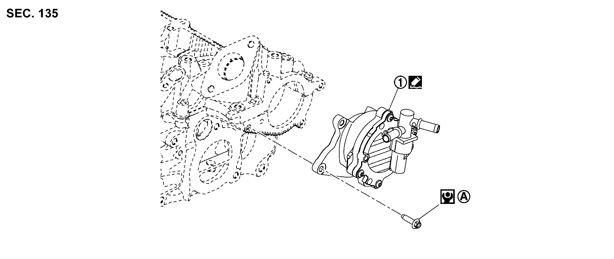
Exploded View
 |
Vacuum pump | ||||
 |
Comply with the assembly procedure when tightening. Refer to Removal and Installation. | ||||
 |
: Sealing point | ||||
 |
: N·m (kg-m, in-lb) | ||||
Removal and Installation
REMOVAL
Remove air duct. Refer to Removal and Installation.
Remove bracket 1 and air duct bracket  .
.
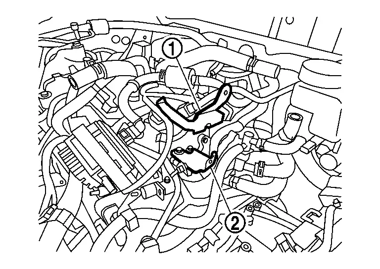
Disconnect vacuum hose from vacuum pump.
Loosen the vacuum pump bolts in reverse of the sequence shown.
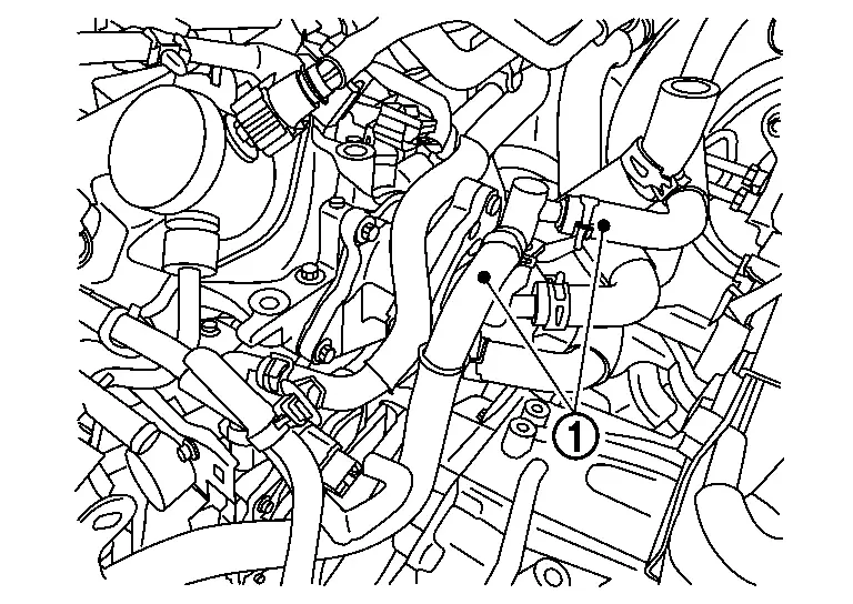
Insert a suitable tool at location and separate the vacuum pump from the cylinder head.
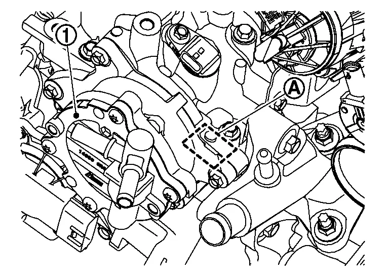
CAUTION:
-
Do not damage the mating surface.
-
The liquid gasket used at the factory is very strong. Pry only in the area shown.
-
Do not disassemble vacuum pump.
INSTALLATION
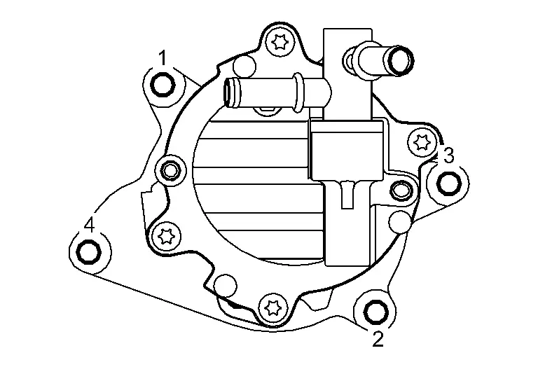
Apply a continuous bead of liquid gasket  with a tube presser (commercial service tool) as shown in the figure.
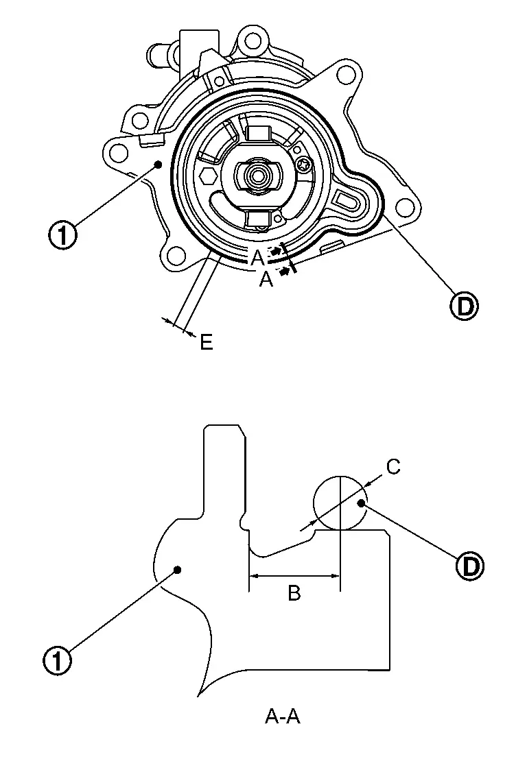
|
: Vacuum pump |
| B | : 5.5 — 7.5 mm (0.217 — 0.295 in) |
| C | : Φ3.4 — 4.4 mm (0.134 — 0.173 in) |
| E | : 5 mm or more (0.20 in or more) |
-
Use Genuine RTV Silicone Sealant or an equivalent. Refer to Recommended Chemical Products and Sealants.
CAUTION:
-
The components must be installed within 5 minutes of the liquid gasket application.
-
Do not re-tighten bolts after the 5 minutes have elapsed.
-
Then allow 30 minutes for the liquid gasket to set before adding oil to the engine.
-
Install the vacuum pump and tighten bolts to the specified torque in the sequence shown.
| Vacuum pump bolts |
: 10.0 N·m (1.0 kg-m, 89 in-lb) |
 NOTE:
NOTE:
Make sure to align the tabs on the back of the vacuum pump with the recesses  in the signal plate [EXH] .
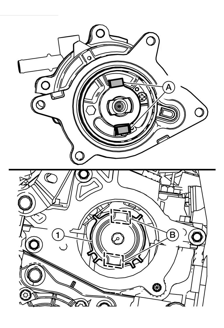
Installation of the remaining components is in the reverse order of removal.
Other materials:
P0011 Ivt Control
DTC Description
DTC DETECTION LOGIC DTC
CONSULT screen terms
(Trouble diagnosis content)
DTC detection condition
P0011
00
INT/V TIM CONT-B1
(“A” Camshaft position - timing over-advanced or system performance bank 1)
Diagnosis condition
Engine running
Signal (term ...
Automatic Drive Positioner
System Description
SYSTEM DIAGRAMSeveral types of signals are transmitted from the following units to the driver seat control unit via CAN communication.INPUT SIGNAL AND OUTPUT SIGNAL Component Signal
ABS actuator and electric unit (control unit)
Nissan Ariya Vehicle speed signal
Combin ...
Symptom Diagnosis. Door Lock Operation Warning Does Not Operate
Diagnosis Procedure
CHECK DOOR LOCK FUNCTION
Check door lock using door request switch.
Does door lock with door request switch?
YES>>
GO TO 2.
NO>>
Refer to Diagnosis Procedure.
CHECK INTELLIGENT KEY WARNING BUZZER
Check Intelligent Key warning buzzer.
Refer to Diagnosis Pro ...