Nissan Rogue (T33) 2021-Present Service Manual: Oil Pan (lower)
Exploded View
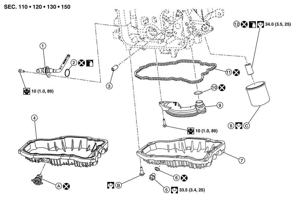
| 1. | Engine oil level sensor | 2. | O-ring 1 | 3. | Relief valve |
| 4. | Oil pan (lower) (With plastic drain plug) | 5. | Drain plug | 6. | Drain plug washer |
| 7. | Oil pan (lower) (With metal drain plug) | 8. | Oil filter | 9. | Oil strainer |
| 10. | O-ring 2 | 11. | Oil pan gasket | 12. | Oil filter stud |
| A. | Comply with the installation procedure when tightening. Refer to Removal and Installation. | B. | Comply with the installation procedure when tightening. Refer to Removal and Installation. | C. | Comply with the installation procedure when tightening. Refer to Removal and Installation. |
 |
: Always replace after every disassembly. | ||||
 |
: N·m (kg-m, in-lb) | ||||
 |
: N·m (kg-m, ft-lb) | ||||
 |
: Should be lubricated with oil. | ||||
Removal and Installation
With metal drain plug
REMOVAL
WARNING:
To avoid the danger of being scalded, never drain the engine oil when the engine is hot.
Remove engine under cover. Refer to Removal and Installation.
Drain engine oil. Refer to Draining.
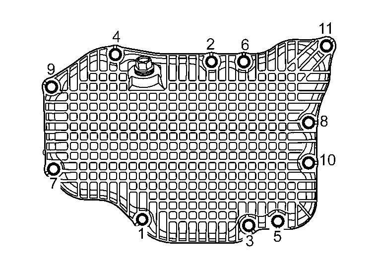
Loosen mounting bolts in reverse order as shown in the figure, and then remove oil pan (lower).
INSTALLATION
CAUTION:
-
Do not reuse o-ring 1 and o-ring 2.
-
Do not reuse drain plug washer.
-
Do not reuse oil pan gasket.
Tighten bolts in numerical order as shown in the figure.
| Oil pan (lower) bolts | ||
| First tighten |
: 2.96 N·m (0.30 kg-m, 26 in-lb) | |
| Second tighten |
: 8.33 N·m (0.85 kg-m, 74in-lb) | |
Install drain plug.
-
Refer to the figure of components of former page for installation direction of washer. Refer to Exploded View.
CAUTION:
Do not reuse drain plug washer.
Install in the reverse order of removal after this step.
With plastic drain plug
REMOVAL
WARNING:
To avoid the danger of being scalded, never drain the engine oil when the engine is hot.
Remove engine under cover. Refer to Removal and Installation.
Drain engine oil. Refer to Draining.
Loosen mounting bolts in reverse order as shown in the figure, and then remove oil pan (lower).

INSTALLATION
CAUTION:
-
Do not reuse o-ring 1 and o-ring 2.
-
Do not reuse drain plug.
-
Use genuine drain plug.
-
Do not reuse oil pan gasket.
Tighten bolts in numerical order as shown in the figure.
| Oil pan (lower) bolts | ||
| First tighten |
: 2.96 N·m (0.30 kg-m, 26 in-lb) | |
| Second tighten |
: 8.33 N·m (0.85 kg-m, 74in-lb) | |
Using suitable tool, install new drain plug and tighten to the lock position in the direction shown.
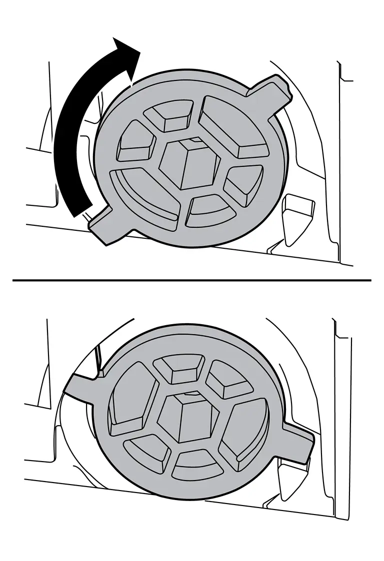
CAUTION:
-
Do not reuse drain plug.
-
Use genuine drain plug.
| Tightening torque | 3 N·m (0.31 kg-m, 27 in-lb | |
Install in the reverse order of removal after this step.
Inspection
INSPECTION AFTER REMOVAL
Clean oil strainer portion if any object attached.
INSPECTION AFTER INSTALLATION
Check the engine oil level and adjust engine oil. Refer to Inspection.
Start engine, and check there is no leakage of engine oil.
Stop engine and wait for 10 minutes.
Check the engine oil level again. Refer to Inspection.
Other materials:
Fonctionnement du système
Capteurs sonar centraux
Capteurs sonar d’angle
Capteurs sonar latéraux (si le véhicule en est équipé)
Le système informe le conducteur par des alertes visuelles et sonores de la présence :
D’obstacles situés à l’avant lorsque le levier de vitesses est en position D (c ...
If your vehicle overheats
WARNING
Never continue driving if your vehicle overheats — this can lead to engine failure or even a vehicle fire.
Never open the hood if steam is coming out.
Never remove the radiator or coolant reservoir cap when the engine is hot. Pressurized coolant can spray out and cause serious ...
P0441 Evap Control System
DTC Description
DTC DETECTION LOGICIn this evaporative emission (EVAP)
control system, purge flow occurs during non-closed throttle conditions.
Purge volume is related to air intake volume. Under normal purge
conditions (non-closed throttle), the EVAP canister purge volume control
solenoid ...